Angry Electrons WordClock-1 User manual

WordClock-1 Assembly Guide 12/08/19 Version 1.2
Page 1
WordClock-1 Assembly Guide
Contents
Introduction...............................................................................................................................2
Assembly..................................................................................................................................2
Bill of Materials .........................................................................................................................6
Warranty Terms and Conditions................................................................................................8
Schematic.................................................................................................................................9

WordClock-1 Assembly Guide 12/08/19 Version 1.2
Page 2
Introduction
WordClock-1 assembly should be attempted only by experienced builders. Although assembly
is straightforward and not difficult, there are several SMD parts that must be carefully
soldered to the boards. The kit may be returned for a full refund less shipping within 30 days
of purchase, only if assembly has not been started.
Assembly
WARNINGS!
DRILL HOLES IN THE CASE BASE FIRST. USE THE CIRCUIT BOARD AS A TEMPLATE.
DO NOT INSTALL THE HEADERS FOR THE ALPHANUMERIC LEDs. REMOVE THE PINS,
OTHERWISE THE BACKLIGHTING WILL BE BLOCKED.
DO NOT SOLDER THE MICROCONTROLLER DIRECTLY TO THE BOARD, USE
HEADERS.
Case
If you purchased the optional acrylic case, this would be a good time to mark and drill the
holes in the base. It is easiest to use an unpopulated circuit board for this purpose. The
precise distance between holes is 156mm wide by 34.5mm deep. The board should not be
centered on its base because the LED displays extend beyond the front of the board.
Step 1 –Build the Main Board

WordClock-1 Assembly Guide 12/08/19 Version 1.2
Page 3
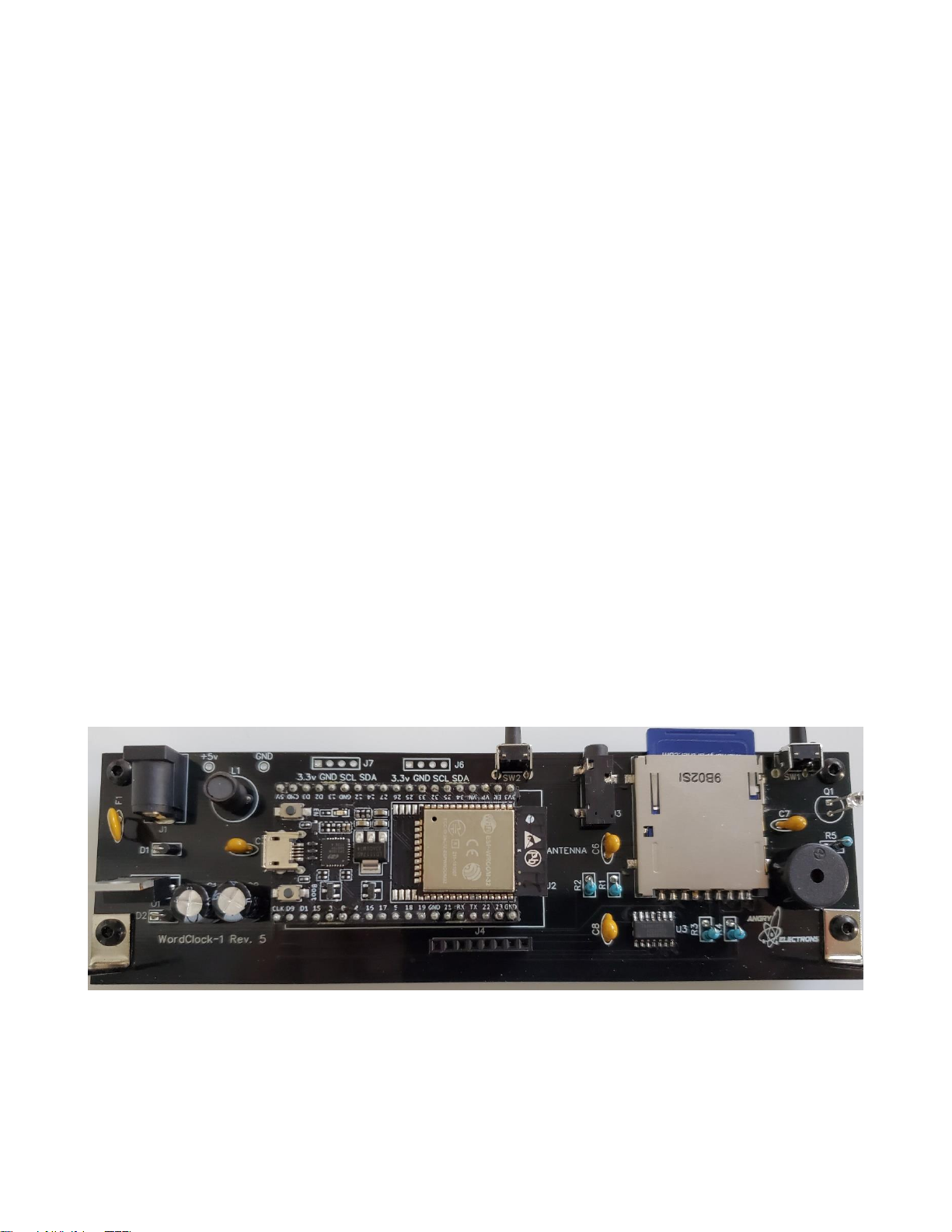
Separate the main board from the display board by bending along the V-
score line.
Build the power supply on the main board. Install J1, F1, C1, C2, C3, D1, D2, L1, and
U1. Note that C1, C2, D1, and D2 must be installed in the direction noted on the board.
Connect a 9-12v power supply with a center positive, 2.1mm connector, and check the
test point for 5v. Do not continue assembly if 5v is not present at the test point.
Install the remaining components on the main board. Start with U3, the 74AHC125D,
14-SOHC chip. The line or dot on one side of the chip must be installed toward the
cutout on one side of the silkscreened pattern. The best way to install a surface mount
chip is to add a very small amount of solder to one of the corner pads for the part.
Then quickly and carefully solder the corresponding pin to the pad. Check the
alignment of all 14 pins and if correct, solder the opposite corner pin. Check the
alignment again, then solder the remaining pins quickly and carefully.
Install the SD card connector next. Be sure to solder all leads to the board. Solder
quickly and carefully. Plastic parts can be damaged by too much heat. Several pins on
one side of the connector are very close to the grounded case. Be careful that they are
only soldered to the pc board, not the case. Then install J3, the GPS connector.
The ambient light sensor, Q1, should be installed about 10mm above the board. The
shorter lead goes toward the back of the board.
Cut the 40 pin female header into two, 19 pin pieces. Install at the U2 location.
DO NOT solder the microcontroller to the board!
Install the remaining parts to the main board. J6 and J7 are not used.
Connect a jumper on the bottom of the board from Q1, the TEPT4400 pin farthest from
the switch immediately behind it, to pin 5 on the microcontroller, U2, labeled IO34 or
G34.

WordClock-1 Assembly Guide 12/08/19 Version 1.2
Page 4
Insert the microcontroller, U2, into the headers aligning the direction of the USB
connector and the antenna with the marks on the board.
Step 2 –Build the Display Board
For ease of assembly, parts should be installed in the order noted here.
Install LED11-LED16. Follow the same procedure noted above to install surface mount
parts. The LEDs must be soldered quickly and carefully. Note the direction. Align the
angled corner with the mark on the board.
Install 470 ohm surface mount resistors at R6-R9. These resistors are used to equalize
the brightness between the display and colons. If a different color colon is used, this
value may have to be adjusted.
Install C9, the surface mount capacitor to the back of the display board.
Install J5, the 90 degree male connector, to the back of the display board. Solder one
pin first, then check the alignment to verify that the pins are parallel to the board.
Cut the silver tape into six pieces and stick to the back of each alphanumeric display,
LED1-LED6. Verify that the tape does not contact any of the pins. The displays are
somewhat translucent so backlighting will show through some segments without the
tape installed. Also, the tape’s reflectivity will increase the visibility of the backlighting.

WordClock-1 Assembly Guide 12/08/19 Version 1.2
Page 5
Do not install the pins in the headers! Remove the pins from the headers! If the round
pins are provided on black plastic headers, they should be removed and individually
installed to allow more visible light around the displays. Hold each header upside down
on the sharp corner of a bench, piece of wood, etc. Grab the back of the pin with a
needle nose plier, and push down hard. The pins will pop out.
Install a round pin onto each pin of LED1-LED6. Use masking tape to hold the displays
in place. Position the display board upside down on a flat surface and solder all pins.
Solder U4 to the back of the display board. Note the direction. Again follow the above
procedure to install surface mount parts.
Install LED7-LED10, the colon LEDs. The short pin goes toward the top of the display
board. Align the colon LEDs so the top is even with the front of the alphanumeric
displays.
Step 3 –Final Assembly
Install two, 10mm standoffs into the holes on the bottom of the main board on the side
with the buttons, using two screws.
Install two standoffs into the holes on the bottom of the main board on the front, along
with the short side of the 90 degree brackets. Put the screw into the short side of the
bracket, then through the main board, and into the standoff.
Plug the display board into the main board, and install two screws and nuts to secure it
to the brackets. The display board should be in front of the brackets.
This completes WordClock-1 assembly. Refer to the User Manual for setup and operating
instructions.

WordClock-1 Assembly Guide 12/08/19 Version 1.2
Page 6
Bill of Materials
Reference
Qty
Part
Value
Note
R1-R2
2
Resistor
4.7k ¼ watt
yellow-violet-red-gold or
yellow-violet-black-brown-gold
R3-R4
2
Resistor
10k ¼ watt
brown-black-orange-gold or
brown-black-black-red-gold
R5
1
Resistor
120k ¼ watt
brown-red-yellow-gold or
brown-red-black-orange-gold
R6-R9
4
Resistor
470R ¼ watt
or 315R
Surface mount. 470R for Orange, Super
Red, and Light Green, Others 315R
C1-C2
2
Capacitor
330uf 25v
Electrolytic
C3-C8
5
Capacitor
100nf
C9
1
Capacitor
100nf
Surface mount 1210 marked 104
D1
1
Diode
1N4001
D2-D3
2
Zener Diode
1N5819
F1
1
Poly Fuse
500mA
Labeled .050
J1
1
Power Jack
2.1mm
J2
1
SD Card
Connector
DM1AA-SF-PEJ
J3
1
Audio Jack
3.5mm
SJ-3523-SMT-TR CUI,Inc.
J4
1
Header
1x8 2.54mm
Female
J5
1
Header
1x8 2.54mm
Male 90 degree
J6-J7
2
Header
1x4
Not used
1
Header
1x40
Cut in two 19 pin for microcontroller
L1
1
Inductor
100uH
LED1-6
6
LED
16 segment .8” LED alphanumeric display
LED7-10
4
LED
3mm LED
LED11-16
7
LED
APA102 SMD RGB LED
Q1
1
Sensor
TEPT4400
Ambient light sensor. Looks like an LED,
clear lens, long leads.
PZ1
1
Buzzer
Piezo buzzer, 11mm lead spacing
SW1-2
2
Button
90 degree pushbutton
U1
1
IC
LM2576T5.0
Switching 5v regulator

WordClock-1 Assembly Guide 12/08/19 Version 1.2
Page 7
Reference
Qty
Part
Value
Note
U2
1
Microcontroller
ESP32
Programmed with WordClock software
U3
1
IC
74AHC125D
Quad buffer SMD
U4
1
IC
HT16K33
LED driver SOP28
108
Pin
Female pins for 16 segment display LEDs
2
Bracket
Keystone 4326
4
Standoff
Threaded 10mm
6
Screw
M3 8mm
2
Nut
M3
1
Silver Tape
Cut to cover the back of each
alphanumeric display
1
SD Card
Programmed with WordClock database
Circuit Board
Display and Main with V-score

WordClock-1 Assembly Guide 12/08/19 Version 1.2
Page 8
Warranty Terms and Conditions
This software and hardware product is Copyright (C) 2019 by Mitchell Feig. It is exclusively
distributed by OCEAN7 Watch Company d/b/a Angry Electrons (“AE”) All Rights Reserved. AE
warrants that for a period of 90 days following delivery, AE kit parts will (a) perform in
accordance with published specifications, and (b) will be free from defects in materials and
workmanship. In the event an AE kit part does not meet this warranty, subject to the
conditions set forth in these terms and conditions, AE’s sole obligation will be, at its election,
to repair or replace the AE kit part in question. AE may require return of the part for
examination and replacement. Replacement will be completed at the sole discretion of AE,
after examining the returned part. Correct assembly is the responsibility of the builder. AE will
not attempt to correct non-working assembled kits.
AE MAKES NO OTHER WARRANTIES, EXPRESS OR IMPLIED, AND ALL IMPLIED WARRANTIES
OF MERCHANTABILITY, NON-INFRINGEMENT AND FITNESS FOR A PARTICULAR PURPOSE
ARE HEREBY DISCLAIMED. IN NO EVENT WILL AE BE LIABLE FOR PUNITIVE, SPECIAL OR
CONSEQUENTIAL DAMAGES, OR FOR AN AMOUNT IN EXCESS OF THE PURCHASE PRICE OF
THE DEFECTIVE AE PART OR PRODUCT.

WordClock-1 Assembly Guide 12/08/19 Version 1.2
Page 9
Schematic

WordClock-1 Assembly Guide 12/08/19 Version 1.2
Page 10
Table of contents
Other Angry Electrons Clock manuals