Anigmo AE-2400-RC User manual

Touchless switch
with isolated relay
Touchless switch with isolated 10Arelay output
Models: AE-2400-RC
CAUTION:
Important notes
1.
2.
3.
4.
5.
6.
Warranty
All products sold or distributed by Anigmo or any of
its subsidiaries are guaranteed to be free from defects
in materials and workmanship for the period of 5 years.
This warranty shall extend to the original end
purchaser only. Anigmo, at its option, shall repair or
replace any Anigmo product within the Terms of
Warranty expressed herein, which fails to meet the
product's specifications.
This warranty does not extend to product failures or
defects caused by, or associated with, but not limited
to; failure to install or maintain correctly, unsuitable
physical or operating environment, accident, force
majeure, hazard, misuse, electrical supply,
unauthorised repair, modification or alteration.
Anigmo will not accept any liability or responsibility
under the terms of warranty expressed herein for,
but not limited to; negligence, loss of profit or data or
damages either material or personal. Mandatory
liability shall be restricted to the sum equal to the
purchase of the product.
This product may be protected by following patents
US 7.531.921, EP 2.038.906, US20090284182,
US 8.339.062, EP 2.292.078
Contact
ANIGMO
Anigmoteh d.o.o.
Tehnoloski park 21
1000 Ljubjana
Slovenia, Europe
www.anigmo.com
email: [email protected]
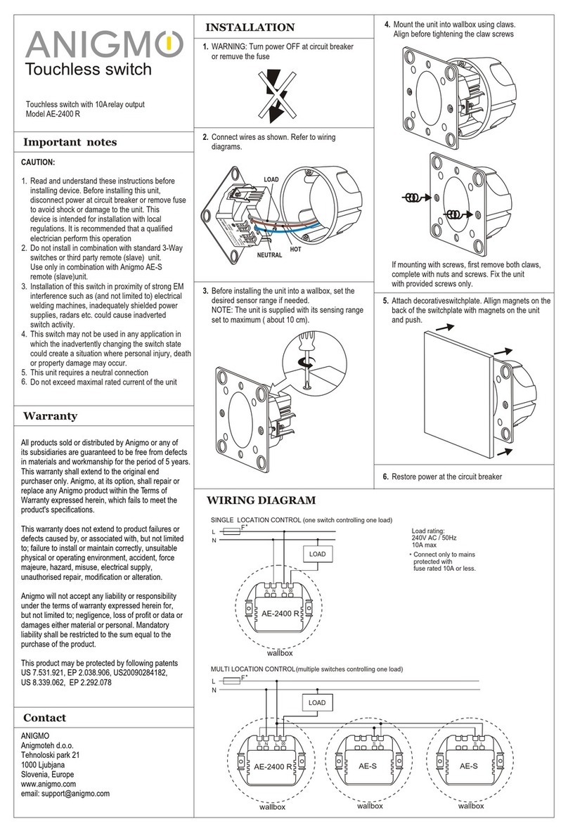
INSTALLATION
1. WARNING: Turn power OFF at circuit breaker
or remove the fuse
2. Connect wires as shown. Refer to wiring
diagrams.
3. Before installing the unit into a wallbox, set the
desired sensor range if needed.
NOTE: The unit is supplied with its sensing range
set to maximum ( about 10 cm).
4. Mount the unit into wallbox using claws.
Align before tightening the claw screws
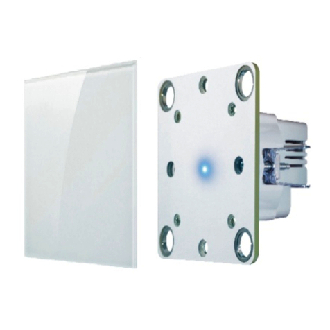
5. Attach decorativeswitchplate. Allign magnets on the
back of the switchplate with magnets on the unit
and push.
L
N
wallbox
AE-2400-RC
NLS
L
N
wallbox
AE-2400-RC
wallbox
AE-S
L
S
wallbox
AE-S
L
S
MULTI LOCATION CONTROL(multiple switches controlling one module)
SINGLE LOCATION CONTROL (one switch controlling one module)
6. Restore power at the circuit breaker
WIRING DIAGRAM
Load rating:
240V AC / 50Hz
10A max
F
F*
*
*Connect only to mains
protected with
fuse rated 10A or less.
RELAY
CONTACTS
HOT
NEUTRAL
If mounting with screws, first remove both claws,
complete with nuts and screws. Fix the unit
with provided screws only.
NO input
COM
Home
Automation
Module**
** Use module manufacturer
connection diagram for
module input connection
NLS
NO input
COM
Home
Automation
Module**
Read and understand these instructions before
installing the device. Before installing this unit,
disconnect power at the circuit breaker or remove
fuse to avoid shock or damage to the unit. This
device is intended for installation with local
regulations. It is recommended that a qualified
electrician perform this operation
Do not install in combination with standard 3-Way
switches or third-party remote (slave) unit.
Use only in combination with Anigmo AE-S
remote (slave)unit.
Installation of this switch in the proximity of strong
EM interference such as (and not limited to)
electrical welding machines, inadequately shielded
power supplies, radars, etc. could cause inadvertent
switch activity.
This switch may not be used in any application in
which the inadvertently changing the switch state
could create a situation where personal injury, death
or property damage may occur.
This unit requires a neutral connection
Do not exceed the maximal rated current of the unit

AE-2400-RC can be used to control any module or system, that accepts contact closure (binary input). Relay contacts are isolated from the line voltage and can be
connected to the module directly.
When AE-2400-RC is connected and powered up, the relay can be activated by moving the hand in front of the switch plate. The RC-2400-RC acts as a momentary
switch. When the hand enters the sensing range (about 5cm from the switch plate), the relay contact will close. When the hand leaves the sensing range the relay opens.
Switchplate can be removed and replaced at any time, without first switching the power off at the fuse. But when removing the switch plate please note, that the switch will
enter the calibration cycle whenever the switch plate is removed, attached, or moved. The cycle will last for about 1-2 minutes during which the switch will be
unresponsive.
Whenever the hand enters the
sensing range in front of the
switchplate lthe relay is activated
Moving the hand while staying in
sensing range doesn’t release
the relay. To release the relay,
the hand must LEAVE the sensing
range.
SYMPTOM
Relay is not clicking
(The switch doesn’t react to hand
movement)
Switch operation is inconsistent
(it doesn’t react consistently to the
hand movements)
Difficult to activate the module
AE-2400RC TOUCHLESS SWITCH OPERATIONAL MANUAL
To activate the relay:
Troubleshooting
Note: Touchless switch with attached switchplate is depicted in the above examples. The switch mechanism is visible in the images for clarity but with typical installation it
would be hidden inside the wall box and only the switchplate would be visible on the wall surface.
POSSIBLE CAUSE
Faulty wiring
Switch entered the calibration mode
Close proximity of moving objects
Unshielded or poorly shielded
transformers or power supplies near
the switch, switch wiring or as a
switch load.
Connected module/system has
a dead time before switching on
SOLUTION
Check if the switch is connected according to the connection diagram.
Check if the fuse is turned on after connecting
If the switchplate is exchanged, moved, removed, or re-attached, the switch
automatically enters the calibration mode, during which it does not react to any
hand movement.
Wait for approx. 1-2 minutes for the unit to complete the cycle.
Switch sensor reacts to any moving object in the sensing range that is large
enough. Check if any object close to the sensor can move into or close to the
sensor range (such as curtains, hanging wires, ropes or wall decoration).
Check if the switch plate is securely fixed. Moving the switch plate even slightly can
cause unreliable switch operation.
Poorly shielded transformers, drivers, and power supplies can cause excessive
EMI (electromagnetic interference), that can cause unreliable switch operation.
Use only certified and properly shielded power supplies.
Reduce sensing range to decrease sensibility
Some systems or modules can have a significant delay between the moment the
push button (relay) is activated and the moment when the system reacts. This delay
can be several seconds in length. Due to this delay, no reaction will be perceived at
the moment the user activates the relay. Auser unfamiliar with this behavior could
falsely think that the switch didn’t react to their command and try to activate
the switch again, possibly nullifying the previous action.
To resolve this, turn the switch on and wait for a couple of seconds. Listen to discrete
click sound from inside of the switch, indicating the switch has actually turned on.
Alternatively, use the switch version with the sound feedback option.
Other Anigmo Switch manuals