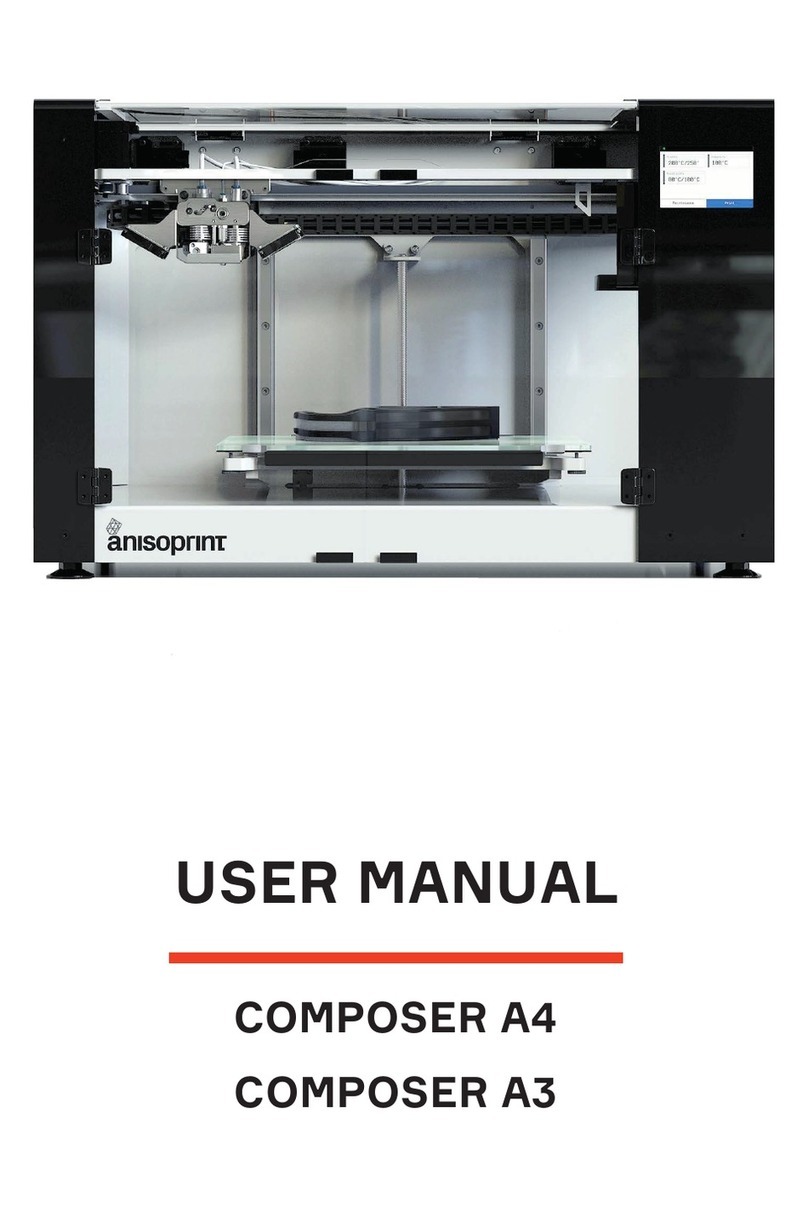
ANISOPRINT Composer User manual

Composer User Manual
by Anisoprint Support
1 / 57

Composer User Manual
1. Disclaimer...................................................................................................... 4
2. Safety instructions ....................................................................................... 4
2.1. Electromagnetic compatibility ...................................................................... 4
2.2. General Precautions ................................................................................... 4
2.3. Precautions when working with carbon fiber ................................................. 5
2.4. Warning symbols ........................................................................................ 5
2.5. Compliance statement ................................................................................ 6
3. Composite Fiber Co-extrusion .................................................................... 6
4. Overview ........................................................................................................ 7
5. Basic specifications ..................................................................................... 7
6. Delivery package .......................................................................................... 8
7. Composer operations................................................................................... 9
7.1. Main screen ............................................................................................... 9
7.2. Installation ............................................................................................... 17
7.3. Loading materials ..................................................................................... 19
7.4. Buildplate calibration................................................................................. 19
7.5. Z-axis calibration ...................................................................................... 20
7.6. Z offset calibration .................................................................................... 20
7.7. XY offset calibration.................................................................................. 21
7.8. Test print ................................................................................................. 23
7.9. In-situ tuning of printing settings ................................................................ 24
7.10. WI-FI connection .................................................................................... 28
7.11. Network bridge software updating ............................................................ 29
8. Maintenance ................................................................................................ 30
8.1. Plastic nozzle replacement........................................................................ 30
8.2. Plastic nozzle cleaning.............................................................................. 31
8.3. Composite extruder channel cleaning ........................................................ 32
8.4. Lubrication ............................................................................................... 36
8.5. Keeping the printer clean .......................................................................... 37
9. Printing materials ....................................................................................... 37
9.1. Plastics .................................................................................................... 37
9.2. Reinforcing fiber ....................................................................................... 39
9.3. Storage of materials ................................................................................. 40
10. Software..................................................................................................... 40
10.1. Interface................................................................................................. 40
10.2. Slicing the model .................................................................................... 41
10.3. System requirements .............................................................................. 43
11. Troubleshooting ....................................................................................... 43
2 / 57

Composer User Manual
11.1. The part get unglued from the buildplate during printing ............................ 43
11.2. Plastic is not extruded from the nozzle ..................................................... 44
11.3. Fiber is not extruded from the nozzle ....................................................... 44
11.4. Strings and poor surface quality of printed part ......................................... 44
11.5. Plastic leaks out of the composite heat block inlet ..................................... 45
11.6. Fiber is clogged inside the composite extruder ......................................... 46
11.7. Fiber is clogged inside the cutter ............................................................. 50
11.8. Fiber is broken before the cutter in the PTFE guiding tube ........................ 54
3 / 57

Composer User Manual
1. Disclaimer
This User Manual is the main document for Composer CFC printers, it is provided with the delivery package. The
Manual guides correct operation, maintenance, and troubleshooting of Composer CFC printers manufactured by
Anisoprint.
Please follow this User Manual when operating and maintaining the equipment. Failure to follow the guidelines
may lead to poor quality of printed parts, damage to the printer, or cause injury, please read the User Manual
carefully.
2. Safety instructions
2.1. Electromagnetic compatibility
Composer CFC printers were tested for compliance with 2014/30/EC guidelines. According to compatibility tests,
the printer is a class A device, which means it can cause additional electromagnetic interference when used at
home.
2.2. General Precautions
Carefully study all precautions before using the printer. When in operation the user should follow all operation
precautions for electrical equipment.
An explanatory note to graphic symbols:
WARNING – indicates a potentially dangerous situation that may result in serious injury or
fatal outcome.
CAUTION – indicates a potentially dangerous situation that may result in minor or moderate injury.
NOTE – indicates a situation that may result in equipment failure.
Basic precautions:
WARNING: do not plug the printer in without grounding!
WARNING: do not touch the print head when printing. The nozzle temperature may be up to 270°?!
WARNING: do not try to repair the printer yourself!
CAUTION: do not use the printer in facilities with ambient temperature lower than 15°C or higher than 35°C!
CAUTION: avoid penetration of water in electronic components of the printer to prevent short-circuit.
CAUTION: disconnect the power cord in case of modifications and maintenance.
4 / 57

Composer User Manual
CAUTION: when connecting power cord to the power line, be sure that the printer ON/OFF switch is in <O>
position.
CAUTION: use the printer in ventilated locations.
CAUTION: the printer is a source of noise; do not use it in leisure areas.
NOTE: do not turn on the printer if the print head is disconnected!
NOTE: place the printer on a level and rigid surface in order to ensure convenient and easy operation with all
elements.
NOTE: when in operations, do not place any objects inside the working zone and inside the printer; do not cover
the printer and the air vents.
NOTE: if the printer is under warranty maintenance, it is not recommended to perform any repair independently!
NOTE: before the first operation be sure that all packaging materials are removed.
NOTE: do not use the printer without the glass at the buildplate!
2.3. Precautions when working with carbon fiber
CFC 3D printing implies work with carbon fiber. Please bear in mind that carbon fiber is a good electrical
conductor. The flow of current through carbon fiber leads to its instant ignition, which may result in injuries and
equipment failure.
WARNING: do not place the printer next to uncovered sockets and laboratory power supply sources in order to
avoid ignition of carbon fiber. Carbon fiber is a good electrical conductor.
If for some reason there occurred a breakage of the composite fiber, do not touch the place of the direct fracture
with unprotected skin. Carbon fiber consists of thousands of thin and sharp threads that can easily get stuck in the
skin, even intact fiber can sometimes cause splinters.
In case of fiber breaking small suspended particles may accidentally get into the eyes or respiratory system. If it is
necessary to examine the components of the Composer CFC Printer at a close distance, where carbon fiber is
outside the protecting tube, be sure to wear safety glasses and protecting mask.
WARNING: do not work with carbon fiber without personal protective equipment – gloves, safety glasses, and
mask.
2.4. Warning symbols
For safety reasons the following symbols can be found on the printer case.
5 / 57

Composer User Manual
Parts marked with this symbol heat up to high temperature and may cause skin burns
Places of grounding connections
Areas of nono-protected contacts under voltage of 220-240V. WARNING: do not take off the protective
cover marked with this symbol
NOTE: please read this manual before using the printer. Keep this manual during the whole
period of operation of the equipment
CAUTION: the manufacturer reserves the right to introduce minor changes (not affecting safety requirements and
operation characteristics) in the design of the printer! Some design changes may not be covered by this user
manual
2.5. Compliance statement
The product is certified in accordance with the applicable technical regulations. The service life is 2 years from the
date of purchase provided the product is not used for anything other than the intended purpose according to the
rules and recommendations described
in this User Manual.
Product certificate: ?181299324
Certificate is valid: from 09.11.2018 through 08.11.2021
Product and services certification authority: Technický skúšobný ústav Pieš?any, š.p.
This equipment complies with Directive WEEE 2012/19/EU for disposal of electric and electronic equipment and
devices. This equipment must be disposed of in accordance with the applicable local waste and safety
regulations. To ensure safety when disposing the equipment it is necessary to follow generally accepted practices
for safe operation when disposing of equipment and devices.
3. Composite Fiber Co-extrusion
Composite Fiber Co-extrusion (CFC) is an additive manufacturing process for production of lightweight and strong
composite parts with a complex shapes and internal structures. The process is based on embedding continuous
composite fiber into the fused plastic through the use of a specially developed print head. The print head shown in
the figure below includes two extruders which are plastic (FFF) and composite (CFC). The composite extruder
6 / 57

Composer User Manual
has two inlets and one nozzle. The central inlet is for composite fiber and the lateral inlet is for plastic. The CF
goes through the central channel and is coated by molten plastics supplied through the lateral channel into the
heat block of the extruder. The CF with the molten plastic is laying up layer by layer through the extruder nozzle
on the work surface. Thus, a composite part reinforced with continuous fibers is forming. The plastic extruder has
one inlet for plastic
filament and one nozzle.
The technology allows manufacturing high-quality reinforced materials while using the flexibility of shapes and a
wide range of plastics.
The technology allows to use various plastics with processing temperatures up to 270°C. You can use ABS, PLA,
PETG, PA, and PC plastics. The material can be varied to achieve the best operational or economic parameters
of the parts depending on the goals.
4. Overview
Composer is a desktop CFC 3D printer available in two formats: A4 and A3. Both machines have heated
buildplates and closed chambers.
5. Basic specifications
7 / 57

Composer User Manual
6. Delivery package
Items in the package:
1. Composer CFC printer – 1 pc.
2. Plastic filament spool – 2 pc.
3. Anisoprint CCF-1.5k fiber spool – 1 pc.
4. Tool kit – 1 pc.
5. Personal protective equipment kit – 1 pc.
8 / 57

Composer User Manual
6. Spare parts kit – 1 pc.
7. Memory card SD – 1 pc.
8. User Manual
7. Composer operations
7.1. Main screen
After switching on the Composer printer, you will see the main screen, which brief description is given below.
1 – Plastic extruder temperature settings button
2 – Buildplate temperature settings button
3 – Composite extruder temperature settings button
4 – print button. To start the print, press this button and select the file of your part from memory device
5 – Maintenance options button. Here, the following options are available:
9 / 57

Composer User Manual
A – Loading/unloading plastic filaments and composite fiber
B – Calibration of the buildplate / Z-axis / print head (Z offset)
C – Printer connection settings
D – Key information about the printer (serial number, version info, build date)
Use axes movement control buttons to move by axes
10 / 57

Composer User Manual
Select movement increment
Use home positioning buttons for tool homing
11 / 57

Composer User Manual
Control XY coordinates of extruder and Z coordinate of
buildplate
Also, you can control material supply. To do it press Extruders button. Here, the following options are available:
Retract/supply plastic filament in plastic extruder
12 / 57

Composer User Manual
Retract/supply composite fiber in composite extruder
Retract/supply plastic filament in composite extruder
13 / 57

Composer User Manual
Select increment for material retract/supply
Control material feed coordinates
14 / 57

Composer User Manual
Change active extruder
Initiate fiber cutting mechanism
15 / 57

Composer User Manual
Switch on/off nozzle blowing fan
E – Composer axes positioning button. Here, the following options are available:
NOTE: these parameters directly affect the printer functionality!
16 / 57

Composer User Manual
F – Printer settings button.
G – Debug info (service information)
7.2. Installation
Your Composer requires several assembly steps before you can start printing.
Unpack the printer and place it on a reliable flat surface, protected from strong vibrations. Adjust the printer feet to
compensate for any unevenness of the surface if needed.
1. Remove blue transportation tape to release the doors and print head
2. Unpack the glass print surface, place it on the buildplate and fix with the clamping clips
17 / 57

Composer User Manual
3. Using a hex key from the Tool kit, attach the spool holders to the back mount of the printer
4. Install the wipe station part on the station bracket on the right for A4 and on the left for A3 Composers. The size
and color may vary with the printer model
5. Plug in the power cable
6. Calibrate the buildplate with an in-built procedure: at the home screen of the printer, go to Maintenance >
Calibarate > Buildplate
7. Calibrate the Z-axis with a built-in procedure in Maintenance > Calibrate > Z-axis
18 / 57

Composer User Manual
7.3. Loading materials
1. Take the 3 spools (plastic, composite plastic, and fiber) out of package and place them
onto the holders.
2. On the Composer screen, click Maintenance > Materials > and choose the material you want to load. Follow
instructions on the screen.
NOTICE: Plastic can leak out of the composite heat block inlet during plastic filament loading in the composite
extruder. Just remove the leaked plastic with tweezers to prevent dripping of the plastic on the printed part.
7.4. Buildplate calibration
Your Composer had already been pre-calibrated before shipping, but due to transport vibrations, it could be
uncalibrated. Thus, you may need to go through the entire calibration procedure after the printer installation.
NOTICE: Clean and preheat the nozzles and the buildplate to its printing temperatures before all the calibration
procedures (buildplate, Z axis, Z-offset) to prevent incorrect calibration.
You need to go through the buildplate calibration procedure after any changes affecting the positioning of the
buildplate, e.g. shaking or moving the printer. While printing a large part occupying the whole buildplate area, you
can notice layer thickness varies from one end of the part to another, which as well means the buildplate requires
recalibration.
19 / 57

Composer User Manual
To start the calibration, go to the main screen, press Maintenance >Calibrate > Buildplate. Follow the instructions.
First, you will be asked to set the plastic nozzle in approximately 1 mm from the buildplate. The first of 3 points is
to be set through the calibration menu,
the left and right corners are tuned manually by adjusting the regulation screws. Second, the procedure is to be
repeated for fine-tuning, this time using a sheet of 80gsm paper to set the lowest possible gap between the nozzle
and the buildplate. The paper must be sliding in the gap with slight friction.
It is recommended to calibrate the Z-axis right after the buildplate calibration.
7.5. Z-axis calibration
The distance between the buildplate and the plastic nozzle tip is quite an important parameter affecting the quality
of your prints. You need to go through this procedure every time you replace the plastic nozzle or if you faced
some issues with laying out the first layer of the print.
Press Maintenance > Calibrate > Z axis and follow the instructions. You will be asked to use a sheet of 80gsm
paper to fine-tune the gap between the nozzle tip and the buildplate.
Print any file to verify the results of the calibration, paying attention to the brim and the first layer layup. You can
tune the first layer height during the print, see IN-SITU TUNING OF PRINTING SETTINGS.
It is recommended to calibrate the Z offset right after the Z-axis calibration.
7.6. Z offset calibration
Z offset defines the relative position of the composite nozzle with respect to the plastic nozzle about Z-axis.
20 / 57
Table of contents
Other ANISOPRINT 3D Printer manuals