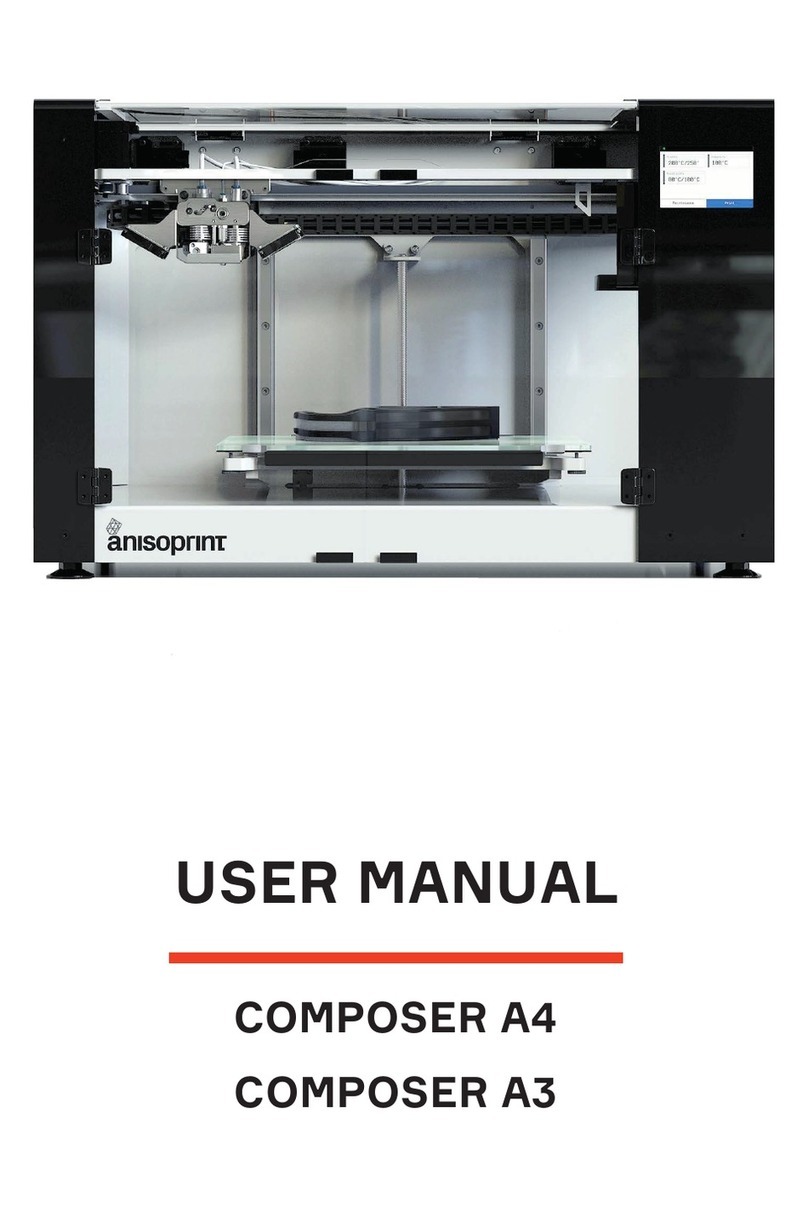
ANISOPRINT COMPOSER A4 User manual

USER MANUAL
COMPOSER A4
COMPOSER A3

TABLE OF CONTENTS
OPENING STATEMENT 2
CFC TECHNOLOGY 3
COMPLIANCE STATEMENT 4
OVERVIEW 5
BASIC SPECIFICATIONS 5
PRECAUTIONS 6
ELECTROMAGNETIC COMPATIBILITY 6
GENERAL PRECAUTIONS 6
PRECAUTIONS WHEN WORKING WITH CARBON FIBER 7
WARNING SYMBOLS 7
DELIVERY PACKAGE 7
QUICK START 8
INSTALLATION 8
LOADING MATERIALS 9
PRINTING THE A TEST PART 9
CALIBRATION 10
BUILDPLATE CALIBRATION 10
Z AXIS CALIBRATION 10
XY OFFSETS CALIBRATION 11
MAINTENANCE 12
PLASTIC NOZZLE REPLACEMENT 12
PLASTIC NOZZLE CLEARING 12
COMPOSITE FIBER CHANNEL CLEANING 13
LUBRICATION 14
KEEPING THE PRINTER CLEAN 14
PRINTING MATERIALS 15
PLASTICS 15
TORAGE OF MATERIALS 15
REINFORCING FIBER 15
SOFTWARE 16
TROUBLESHOOTING 17

2anisoprint.com↗
OPENING STATEMENT
Thank you for purchasing Composer CFC Printer. Your printer allows you to produce parts reinforced with carbon fiber, which will
provide them with high strength and stiffness parameters, incomparable with base plastics. We are confident that our technology will
give you the opportunity to radically change the approach to the design of your product. Use of composite fiber when printing will
save you time - you will get a functional part immediately after the printing process. Saving time and units of production equipment
will provide you with ample opportunities and a high rate of translating your design from the state of a great idea to the production
sample.
Reinforce your ideas, ANISOPRINT TEAM

3
anisoprint.com↗
CFC – TECHNOLOGY
The developed technology represents a deep modification of FFF method (Fused Filament Fabrication), and is known as CFC
(Composite Filament Co-extrusion). It is based on feeding continuous reinforcing fiber directly in the melt of thermoplastic material
prior to extrusion during the printing process. The provided technology of composite parts manufacturing is as follows: pre-
impregnated cured composite reinforcing fiber and thermoplastic filament are fed to the specific composite extruder of the print
head. The extruder is heated to the processing temperature of thermoplastic polymer. Composite reinforcing filament running
through the extruder is covered by polymer melt and goes out through the nozzle. The extruder moves along the programmed path,
laying the reinforcing fiber and molten polymer on the table, thus forming a part. An outline of the technology principle is shown
down.
The technology allows to use as a matrix various plastics with processing temperature up to 250°C, used for prototyping. It can
be ABS, PLA, polyamide(PA), polycarbonate(PC). Depending on the needs of the user, the materials can be varied to achieve the best
operational or economic parameters of the parts.

4anisoprint.com↗
This User Manual is an integral part of the printer and shall be provided to a buyer immediately with sale of the printer. This User
Manual applies to Composer CFC Printer, designed for manufacture of products of complex shape and internal structure from
thermoplastic material, reinforced by continuous composite filaments based on carbon bundles and thermoreactive binder.
The Manual covers correct operation, maintenance and troubleshooting of Composer CFC Printer, manufactured by Anisoprint.
Please follow the requirements of this User Manual when operating and maintaining the equipment
NOTE: PLEASE READ THIS MANUAL BEFORE USE. KEEP THIS MANUAL
DURING THE WHOLE PERIOD OF OPERATION OF THE EQUIPMENT.
CAUTION: THE MANUFACTURER RESERVES THE RIGHT TO INTRODUCE
MINOR CHANGES (NOT AFFECTING SAFETY REQUIREMENTS AND
OPERATION CHARACTERISTICS) IN THE DESIGN OF THE PRINTER! SOME
DESIGN CHANGES MAY NOT BE COVERED BY THIS USER MANUAL
Product is certified: 181299324
Certificate is valid: from 09.11.2018 through 08.11.2021
Product and services certification authority – Technický skúšobný ústav Piešťany, š.p.
This equipment complies with Directive WEEE 2012/19/EU for disposal of electric and electronic
equipment and devices. This equipment must be disposed of in accordance with waste and safety
requirements. To ensure safety when disposing the equipment it is necessary to follow generally
accepted practices for safe operation when disposing of equipment and devices.
COMPLIANCE STATEMENT
The product is certified in accordance with technical regulations. The service life is 3 years from the date of sale provided the
product is not used other than the intended purpose according to the rules and recommendations described in this user manual.

5
anisoprint.com↗
OVERVIEW
Composer CFC Printers for manufacture parts and products from composites are devices for co-extrusion of double matrix
composite and are designed for manufacture of products of complex shape and internal structure from thermoplastic material,
reinforced by continuous composite filaments based on carbon bundles and thermoreactive binder.
BASIC SPECIFICATIONS
А4 А3
Printing technology Fused Filament Fabrication (FFF); Composite Filament Co-extrusion (CFC)
Print bed size 297mm 210mm 145mm 420mm 297mm 210mm
Layer thickness, min. 60 µm
Print head Double-nozzled (extruder FFF; extruder CFC with reinforcing fiber cutting device)
FFF Nozzle diameter 0.4 mm
Print speed for FFF 10 mm/sec – 80 mm/sec
Print speed for CFC 1 mm/sec – 10 mm/sec
Plastic filament diameter 1.75 mm
Compatible plastics Plastics with processing temperatures up to 270°
Reinforcing filament Anisoprint CCF-1.5k or CBF
Platform surface Glass
TEMPERATURE
Print head operating
temperature, max. 270°
Buildplate operating
temperature, max. 60° (up to 120° with open print chamber)
Ambient operating
temperatures 18 – 28°
SOFTWARE
Slicer Anisoprint Aura(FFF+CFC), Cura,Slic3r(only FFF)
OS support Windows 7+
POWER REQUIREMENTS
Voltage 220-240 V
Frequency 50/60 Hz
Maximum output 800 W 1000 W
PHYSICAL CHARACTERISTICS
Weight 25 kg 55 kg
Dimensions with packaging 780510510 930800660
Printer size (LxWH) 610400400 720630490
Interface SD-card slot, USB-Type B

6anisoprint.com↗
PRECAUTIONS
ELECTROMAGNETIC COMPATIBILITY
Composer CFC Printers were tested for compliance with 2014/30/EC guidelines. According to compatibility tests, the printer is a
class A device, which means it can cause additional electromagnetic interference while used at home.
GENERAL PRECAUTIONS
Before use the printer operator shall carefully study all precautions. When in operation the use shall follow all precautions for
operation of electrical equipment.
Explanatory note to graphic symbols:
WARNING – Indicates a potentially hazardous situation which, if not avoided, may result in
serious injury or fatal outcome.
CAUTION – Indicates a potentially hazardous situation which, if not avoided, may result in minor
or moderate injury
NOTE – Indicates a situation which, if not avoided, may result in equipment failure
Basic precautions:
WARNING: DO NOT PLUG THE PRINTER IN WITHOUT GROUNDING!
WARNING: DO NOT USE THE PRINTER WITHOUT GLASS AT THE BUILDPLATE!
WARNING: DO NOT TOUCH THE PRINT HEAD WHEN PRINTING.
TEMPERATURE OF THE NOZZLE MAY BE UP TO 250°!
WARNING: DO NOT USE THE PRINTER IN PREMISES WHERE AMBIENT
TEMPERATURE IS LOWER THAN 15° OR EXCEEDS 35°!
WARNING: DO NOT START THE PRINTER IF THE HEAD IS DISCONNECTED!
CAUTION: DISCONNECT POWER CORD IN CASE OF MODIFICATIONS AND
MAINTENANCE.
CAUTION: WHEN CONNECTING POWER CORD TO THE POWER LINE, BE SURE
THAT PRINTER ON/OFF KNOB IS IN <O> POSITION.
CAUTION: PLACE THE PRINTER ON PLACE AND RIGID SURFACE IN ORDER
TO ENSURE CONVENIENT AND EASY OPERATION WITH ALL ELEMENTS.
CAUTION: USE THE PRINTER IN VENTILATED LOCATIONS.
CAUTION: THE PRINTER IS A SOURCE OF INCREASED NOISE; DO NOT USE IT
IN LEISURE AREAS.
NOTE: WHEN IN OPERATION DO NOT PLACE ANY OBJECTS INSIDE THE
WORKING ZONE AND INSIDE THE PRINTER; DO NOT COVER THE PRINTER
AND AIR VENTS.
NOTE: IF THE PRINTER IS UNDER WARRANTY MAINTENANCE, IT IS NOT
RECOMMENDED TO PERFORM FAULT REPAIR INDEPENDENTLY!
NOTIFY THE NEAREST SERVICE CENTER OF ANY MALFUNCTIONS!
NOTE: AVOID PENETRATION OF WATER IN ELECTRONIC COMPONENTS OF
THE PRINTER TO PREVENT SHORT-CIRCUIT.
NOTE: BEFORE THE FIRST OPERATION BE SURE THAT ALL PACKAGING
MATERIALS ARE REMOVED.

7
anisoprint.com↗
PRECAUTIONS WHEN WORKING WITH CARBON FIBER.
CFC Technology printing implies operations with composite bundle based on carbon filaments. Please bear in mind that carbon
fiber is a good current conductor. The flow of current through carbon fiber leads to its instantaneous ignition, which may result in
injuries and equipment failure.
WARNING: DO NOT PLACE THE PRINTER NEXT TO UNCOVERED SOCKETS
AND LABORATORY POWER SUPPLY SOURCES IN ORDER TO AVOID IGNITION
OF CARBON FIBER. CARBON FIBER IS A GOOD CURRENT CONDUCTOR.
If for some reason there is a fracture of the composite fiber, do not touch the place of the direct fracture by unprotected skin
areas. Carbon fiber consists of thousands of thin and sharp filaments that can easily get stuck in the skin, even intact fiber can
sometimes leave splinters.
In case of fiber breaking small suspended particles may accidentally get into the eyes or respiratory system. If it is necessary to
examine the components of the Composer CFC Printer at a close distance, where carbon fiber is outside the protective tube, be sure
to wear safety glasses and protecting mask.
WARNING: DO NOT WORK WITH CARBON FIBER WITHOUT PERSONAL
PROTECTIVE EQUIPMENT – GLOVES, SAFETY GLASSES AND MASK .
WARNING SYMBOLS
For reasons of safety the following symbols can be found on the printer case.
PARTS MARKED WITH THIS SYMBOL HEAT UP TO 270°
PLACES OF GROUNDING CONNECTIONS
AREAS OF NON-PROTECTED CONTACTS UNDER VOLTAGE OF 220-240V
WARNING: DO NOT TAKE OFF THE PROTECTIVE COVER MARKED WITH THIS
SYMBOL.
DELIVERY PACKAGE
Items in the package:
1. Composer CFC Printer– 1 pc.
2. PETG plastic spool – 2 pc.
3. Anisoprint CCF-1.5k fiber spool – 1 pc.
4. Tool kit – 1 pc.
5. Personal protective equipment – 1 pc.
6. Spare parts kit– 1 pc.
7. Memory card SD 4GB – 1 pc.
8. User Manual

8anisoprint.com↗
QUICK START
INSTALLATION
Your Composer printer requires several assembly steps to be performed before you start printing.
Unpack the printer and place it on a reliable flat surface, protected from strong vibrations. Adjust the printer feet to compensate
for any unevenness of the surface if needed.
1. Using a hex key from the Tool kit, attach the spool holders to the back mount of the printer
5. Calibrate the buildplate via automatic procedure in Maintenance > Calibarate > Buildplate. Calibrate the Z-axis via
automatic procedure in Maintenance > Calibrate > Z-axis.
2. Install the wipe station part on the station bracket on the right. Size and color may vary by model.
3. Unpack the printing glass, apply an adhesive varnish evenly to the top surface, place it on the buildplate and fix with the
clamping clips.
4. Plug in the power cable.

9
anisoprint.com↗
PRINTING THE A TEST PART
Test part “letter A” introduces you to capabilities of your Composer A4 and also serves as a combined quality test.
Press Print > A_letter_test.gcode .
After print start, both extruders, plastic and composite, start to heat. When composite extruder reaches 235°C composite nozzle
will print a short purge composite line in front of the build plate. It must be glued to the surface and look smooth and uniform. At the
end of printing the purge line you will hear a characteristic sound of the fiber cutter.
After printing the purge line, the machine will start with the first plastic layer. Check if the plastic perimeters look the same
everywhere along the part. The first layer must be nicely glued to the build plate. At the same time, wipe tower will be started on the
left side of the build plate.
After several plastic series, the machine will go the first fiber perimeter. Due to the process features, it may look a bit wobbly, but
the layup paths will normalize later on. During the next plastic-composite cycles, fiber perimeters will be surrounded by plastic ones.
Make sure the plastic and fiber perimeters do not intersect, and fiber perimeters are laid without displacements.
Inspect the printed part, paying special attention to side walls quality. Check the surface smoothness visually. You can compare it
to the wipe tower side, the quality of the print must be roughly the same.
1 – Fiber perimeters
2 – Plastic perimeters
3 – Cellular infill
4 – Top and bottom solid layers
LOADING MATERIALS
1. Take the 3 spools (Plastic, Composite Plastic and
Fiber) out of dry bags and place them onto
the holders.
2. On the Composer screen, click
Maintenance > Materials > and choose the material
you want to load. Follow instructions on the screen.

10 anisoprint.com↗
CALIBRATION
BUILDPLATE CALIBRATION
You may need to go through calibration procedure every time you replace a nozzle or after any other changes affecting relative
positioning of the print head and the buildplate, e.g. shaking or moving the printer. While printing a large part occupying the whole
buildplate area, you can notice layer thickness varies from one end of the part to another, which as well means the buildplate requires
recalibration.
It’s highly recommended to preheat plastic nozzle before calibration
To start calibration, on the main screen press Maintenance. Choose Calibrate > Buildplate. Follow instructions. First, you will be
asked to set the plastic nozzle in approximately 1 mm from the buildplate. The first of 3 points is to be set through the calibration
menu, and the left and right corners are tuned manually by adjusting the regulation screws. Second, the procedure is to be repeated
for fine tuning, this time using a sheet of 80gsm paper to set the lowest possible gap between the nozzle and the buildplate. The
paper must be sliding in the gap with a slight friction. Setting insufficiently low gap will lead to failed prints and printer malfunction.
It is recommended to calibrate Z axis right after buildplate calibration.
Z AXIS CALIBRATION
The distance between buildplate and plastic nozzle tip is quite an important parameter affecting the quality of your prints. If it
seems that plastic layers are too thin or too thick, nozzle tip scratches buildplate or previous layers or the quality of vertical walls of
your model is insufficient due to improper plastic layup, try this procedure.
Press Maintenance > Calibrate > Z axis and follow the instructions. You will be asked to use a thin paper sheet to fine tune the gap
between the nozzle tip and the buildplate.
Print any code to verify the results of the calibration, paying attention to brim and first layer layup.

11
anisoprint.com↗
XY OFFSETS CALIBRATION
XY offsets define relative position of composite nozzle with respect to plastic nozzle. You typically need to go through this
procedure once after nozzle replacement or cleaning.
In order to calibrate, print the special service code NozzleOffsetTest.gcode from the SD card supplied with your Composer A4. You
can also download it from support.anisoprint.com
After printing you will see the following: To adjust the offsets, use this scheme:
For every axis find the rectangle where the composite fiber is right in the middle as shown on the Reference scheme. The distance
of this rectangle to zero rectangle is the number you need to add to/subtract from the current offset value.
To change these values go to Maintenance > Settings
After adjusting the offsets, reprint the offset test and make sure that composite fiber is properly centered(as on the Reference
scheme) for both X and Y zero rectangles.

12 anisoprint.com↗
MAINTENANCE
PLASTIC NOZZLE REPLACEMENT
You might want to clean inner surface of a nozzle – chemically or mechanically.
1. Using the 2mm hex key from Tool Kit loosen the side screws of fan bracket. Remove the fan bracket carefully, fan bracket
stays hang on wires.
2. Heat the plastic extruder up to 200C°
3. Using the 7 mm socket wrench unscrew the plastic nozzle from the plastic extruder – turn it clockwise, do not use too much
force to avoid damage of the composite nozzle
4. Clean or replace the nozzle.
CAUTION: All extruder parts can be hot!
PLASTIC NOZZLE CLEARING
To clean plastic nozzle, follow the next simple steps:
1. Heat composite extruder up to 250C°.
2. Clean the nozzle with cleaning needle from tool kit or you can use any stiff steel wire with 0.35 diameter.
3. To finish the clearing procedure, feed about 50mm of plastic to the extruder.

13
anisoprint.com↗
COMPOSITE FIBER CHANNEL CLEANING
Do this only if you are sure the fiber was jammed inside the extruder. Before the start, remove the fan bracket as explained in
Nozzle cleaning section.
1. Using a hex key from the Tool kit, loosen the 2 screws on the front of the extruder.
2. Remove composite extruder.
3. Unscrew the fiber feed tube and check for the broken fibers inside.
4. Use a pair of tweezers to clean the trimming system.

14 anisoprint.com↗
LUBRICATION
To extend the service life of the Composer CFC Printer, the mechanical parts of the product must be serviced periodically. The
service includes lubrication of moving nodes: guides of X, Y, Z-axes, Z-axis screw and plastic extruder. The delivery package includes
two types of lubricants: for the plastic nozzle and guide axes. lubrication of mechanical parts of the printer is recommended at least
once every six months.
KEEPING THE PRINTER CLEAN
In case of frequent use of the printer, small particles of plastic and fiber may accumulate in the internal space. From time to time
clean the printer platform from accumulated particles and dust by using microfiber and a vacuum cleaner.
Glass of the print bed will inevitably accumulate particles of plastic and fiber, fixing varnish or glue. To improve adhesion of the
part when printing and the quality of the first layers of the product, it is recommended to clean the surface of the glass before each
print with damp cloth.

15
anisoprint.com↗
PRINTING MATERIALS
PLASTICS
Composer printer combines two printing technologies FFF-technology and CFC - technology. Different in their properties and
characteristics of the materials may be used for these options of fabrication of parts. When considering FFF technology, it is possible
to use all types of plastics available on the market with a suitable processing temperature range (up to 250°C) and a diameter of 1.75
mm.
As for CFC-technology, it is allowed to use the recommended plastics, which, when interacting with a composite bundle, make it
possible to achieve better quality of the final part. Options of the plastics used are listed in table
Recommended plastics PLA/PET-G
Compatible plastics PLA/ABS/PC/PA/PET-G
REINFORCING FIBER
For printing with reinforcement a specially prepared patented
composite fiber Anisoprint CCF is used, which provides high-
quality adhesion to plastic and fiber impregnation. Anisoprint
CCF is a composite reinforcing fibre in the form of a tow made of
thousands of ultrathin carbon monofilaments, impregnated with a
special polymer composition ensuring high-quality impregnation
and adhesion between the polymers and the fibre. Composite fibre
is used to reinforce the plastic during fabrication of the part.
CAUTION: THE MANUFACTURER DISCLAIMS ANY RESPONSIBILITY FOR THE
EFFECTS OF USE OF NON-RECOMMENDED MATERIALS, IMPROPER STORED
MATERIALS; WHEN OTHER MATERIALS INSTEAD OF RECOMMENDED
REINFORCING FIBER ARE USED.
USE OF MATERIALS NOT RECOMMENDED IN THIS MANUAL MAY RESULT IN
DAMAGE OR COMPLETE FAILURE OF THE EQUIPMENT!
Effective
Diameter, mm VF, % Elastic
Modulus, GPa
Tensile
Strength, MPa
0.36±0.02 57±7 135±15 2130±230
STORAGE OF MATERIALS
Most plastics used in 3D-printing tend to accumulate moisture (hygroscopic). In its turn, the presence of moisture in filament will
cause boiling of the liquid during printing, which will result in uneven supply of plastic and as a consequence in defect in the quality
of the final part. Some types of plastics are less sensitive to presence of moisture in the surrounding space, but for better surface
quality it is recommended to store plastic filaments in places with a minimum amount of moisture. The solution to this problem (for
PET-G) is pre-drying for 4-8 hours of the spool with filament in a convection oven at 60-80°C and their further storage in the air-tight
container with any adsorbing agent (e.g. silica gel).
Carbon fiber, which is part of the composite bundle, is also a hygroscopic material. Similar to plastics it is required to choose
spaces with minimum moisture content in the air for its long-term storage.

16 anisoprint.com↗
SOFTWARE
Anisoprint Aura is a slicer that prepares 3D models for manufacturing parts using Composer CFC printer as well as conventional
FFF-printers.
Aura prepares a 3D model, generates reinforcing fiber trajectories in each layer and allows to adjust reinforcement scheme to
obtain strong and lightweight parts. It enables to combine micro and macro layers, making it possible to print an infill with thick
layers and an external shell with thin layers. This feature results in faster printing without loss of quality.
In case you need to print individual non-reinforced elements, Aura allows you to print small elements with FFF-nozzle without fiber.
Aura is easy to use, with stylish interface and a wide range of practical and versatile features. Aura can generate reliable supports for
printing complex objects and shows the model to be printed layer by layer. Model processing is fully automated and executed using a
local computer ensuring confidentiality and safety of user’s data.
Anisoprint Aura can be dowload from the website anisoprint.com/product-aura

17
anisoprint.com↗
TROUBLESHOOTING
Problem or error message Recommended solution
Plastic is not extruded from the
nozzle
Check whether the plastic is correctly loaded in the feeder; Whether plastic filament comes to the
print-head.
Check that the temperature of the extruder meets the recommended processing temperature of
the plastic;
Nozzle clogged. Heat the extruder and clean the nozzle with the supplied needles; or replace the
nozzle.
Fiber is not extruded from the
nozzle
Check whether the correct fiber is correctly loaded in the feeder. Whether the fiber comes to the
print-head.
Check whether the temperature of the composite extruder corresponds to the temperature of the
plastic processing for the fiber.
Nozzle clogged. Trim the fiber using the menu item. Clean the composite nozzle with tweezers and
a nozzle cleaning needle from the kit.
The part get unglued from
the printing platform during
printing
Check that the temperature of the printing platform matches the recommended temperature for
the plastic.
Insufficient amount of varnish/glue is applied to the printing surface. Try increasing the amount of
adhesive.
The height of the first layer is incorrect. Calibrate the printing platform using the menu item
Calibrate.
For more information, please refer to website: support.anisoprint.com
When detecting a fault in operation of the equipment you must immediately discontinue its operation and contact the nearest
service center of “Anisoprint”. For safety reasons all operations related to repair and maintenance of the equipment must be performed
only by the authorized representatives of the service centers of “Anisoprint”. Please contact your local distributor or write us on
suppor[email protected]
Other manuals for COMPOSER A4
1
This manual suits for next models
1
Table of contents
Other ANISOPRINT 3D Printer manuals