ADITIVA 3D ENDER 3 BELT KIT 45 User manual


Ender 3 Belt Kit ADD-ON assembly manual P a g e 2 | 15
www.belt3dprinterkit.com
Content
Chapter 1 Intro 3
Step 1.1 What is included in this kit? 3
Step 1.2 Additional printable parts 3
Step 1.3 Needed tools 4
Chapter 2 Disassembling parts to be replaced 4
Step 2.1 Remove all axis V-Wheels 4
Step 2.2 Removing other hardware 7
Chapter 3 Mounting new parts 7
Step 3.1 Installing new Top corner brackets and belt tensioners 7
Step 3.2 Getting X axis ready 8
Step 3.3 Getting Direct extruder ready 10
Step 3.4 Diagonal axis Rails mounting 11
Step 3.5 X axis mounting 13
Step 3.6 Faceplate mounting 15
Step 3.7 Wiring 15

Ender 3 Belt Kit ADD-ON assembly manual P a g e 3 | 15
www.belt3dprinterkit.com
Chapter 1 Intro
Step 1.1 What is included in this kit?
In this kit you will find all the necessary parts for upgrading your Ender 3 Belt KIT 45 to linear
rails mechanics and direct extruder setup, but some additional 3d printed parts might be
necessary as well (STL files will be provided). Parts lists are indicated on each step for better
understanding and guidance.
Step 1.2 Additional printable parts
There are few printable parts for finish this build, since they will be provided as STL digital
format, they are subject to upgrades and few more will be added in the future, please check for
regular updates.
X Axis endstop bracket (x1)
Figure 1 X Axis endstop bracket
Rail Stop (x4)
Figure 2 Rail stop
Fan Shroud (x1)
Figure 3 Turbo fan shroud

Ender 3 Belt Kit ADD-ON assembly manual P a g e 4 | 15
www.belt3dprinterkit.com
Step 1.3 Needed tools
In order to fully install this kit, you will need the next tools:
Set of Allen keys
Adjustable wrench or wrench kit
Measuring tape
Vernier caliper
Chapter 2 Disassembling parts to be replaced
In order to get ready to install this kit, you have to disassembly various segments of the Ender 3
BELT 45, this part will guide you through entire process of preparation and getting ready to
install this upgrade kit.
*Please be aware some original parts will be discarded and won’t be installed.
Figure 4. Assembled Ender 3 BELT 45
Step 2.1 Remove all axis V-Wheels
Detach X axis timing belt and remove top nuts in order to take wheels apart.

Ender 3 Belt Kit ADD-ON assembly manual P a g e 6 | 15
www.belt3dprinterkit.com
Figure 7 Cut zip ties and release timing belts
Remove nuts that holds V-wheels from left and right side of diagonal axis, take out V-
wheels, spacers, eccentrics and back plates from both sides.
Figure 8 removing left side components

Ender 3 Belt Kit ADD-ON assembly manual P a g e 7 | 15
www.belt3dprinterkit.com
Figure 9 removing right side components
Step 2.2 Removing other hardware
Disassembly top corners, including idler pulleys, save bolts and nuts for later use.
Figure 10 Take apart top corners brackets
Chapter 3 Mounting new parts
Step 3.1 Installing new Top corner brackets and belt tensioners
Next items from the KIT will be used:
ITEM
ITEM DESCRIPTION
Quantity
Origin
1
Left top corner for belt tensioner
1
ADD-ON kit
2
Right top corner for belt tensioner
1
ADD-ON kit
3
M4 x 8 mm Screw
10
Belt kit
4
M4 Slot nut
10
Belt kit

Ender 3 Belt Kit ADD-ON assembly manual P a g e 8 | 15
www.belt3dprinterkit.com
5
Belt tensioner
2
ADD-ON kit
Install Top corner brackets and tensioners as shown in the next picture:
Figure 11 Mounting new top corners and tensioners
Figure 12 Top brackets and tensioners installed
Step 3.2 Getting X axis ready
Next items from the KIT will be used:
ITEM
ITEM DESCRIPTION
Quantity
Origin
1
X axis end-stop bracket
1
Printed part
2
300 mm Linear rail with slider
1
ADD-ON kit
3
M3 x 8 mm Screw
5
ADD-ON kit
4
M3 Slot nut
5
ADD-ON kit
5
Belt tensioner
1
ADD-ON kit
Install X axis end-stop bracket, using M3x6 screws, you will need to take plastic cover
apart in order to attach it, then put it back and mount X axis end-stop:

Ender 3 Belt Kit ADD-ON assembly manual P a g e 9 | 15
www.belt3dprinterkit.com
Figure 13 X axis end-stop modification
Install X axis rail, using 5 units M3x8 mm screws and M3 T-nuts, push rail against X
end-stop bracket on the left, install screws on both ends first, then one in the center
and 2 extra evenly distanced, you can install X axis belt tensioner, and timing belt as
well:
Figure 14 Screws position + X belt tensioner

Ender 3 Belt Kit ADD-ON assembly manual P a g e 10 | 15
www.belt3dprinterkit.com
Step 3.3 Getting Direct extruder ready
Next items from the KIT will be used:
ITEM
ITEM DESCRIPTION
Quantity
Origin
1
Biqu H2 V2 direct extruder
1
Printed part
2
Extruder Bracket P4
1
ADD-ON kit
3
Extruder Bracket P5
1
ADD-ON kit
4
Fan shroud
1
Printed part
5
5015 Turbo Fan
1
ADD-ON kit
6
M3x8 Screw
10
ADD-ON kit
7
M3x18 Screw
2
ADD-ON kit
8
Mk8 Nozzle (0.4, 0.6 and 0.8mm)
1 each
ADD-ON kit
Mount Biqu H2 v2 extruder with the Extruder bracket P4, using 4 units M3x8 Screw:
Figure 15 Extruder bracket with BIQU H2 V2 direct extruder
Mount supplied Hot-end fan on the heatsink side of the extruder (screws are supplied),
at this point you can install supplied 5015 TURBO FAN with printed fan shroud using 2
units M3x8 screws to the extruder, and 2 units M3x18 screws to the printed fan shroud,
also at this point you can change original nozzle with one of the extra Mk8 nozzle
supplied on the kit:
Extruder bracket p4

Ender 3 Belt Kit ADD-ON assembly manual P a g e 11 | 15
www.belt3dprinterkit.com
Figure 16 Fans mounting, extruder ready
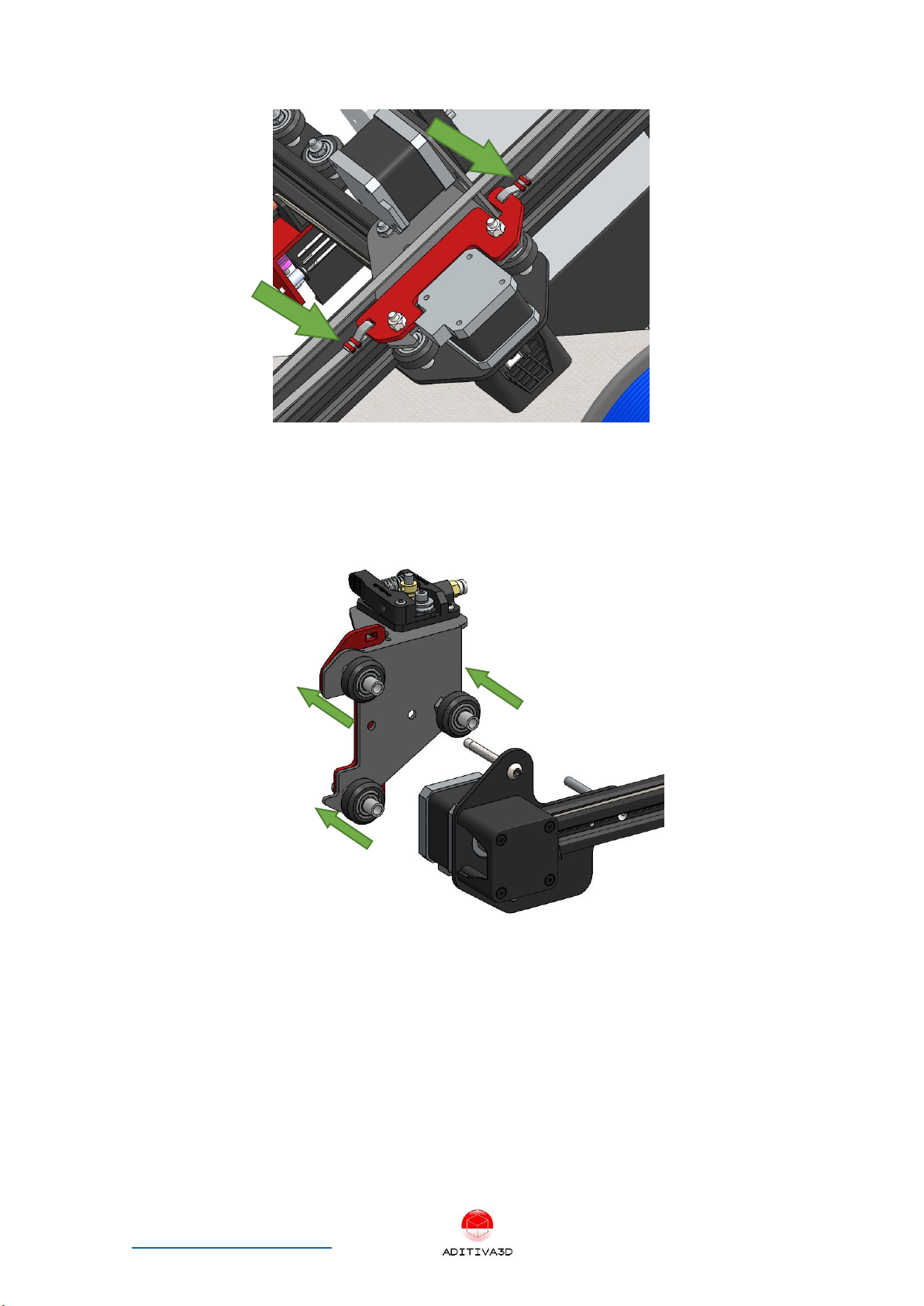
Using Extruder Bracket P5 and 4 units M3x8 Screws, mount the extruder assembly
with the X axis slider, as shown in the next picture:
Figure 17 Extruder assembly mount
Step 3.4 Diagonal axis Rails mounting
Next items from the KIT will be used:
Ender 3 Belt Kit ADD-ON assembly manual P a g e 12 | 15
www.belt3dprinterkit.com
ITEM
ITEM DESCRIPTION
Quantity
Origin
1
Rail stop
4
Printed part
2
300 mm Linear rail with slider
2
ADD-ON kit
3
M4x8 mm Screw
4
ADD-ON kit
4
M4 Slot nut
4
ADD-ON kit
5
M3x8 mm Screw
10
ADD-ON kit
6
M3 Slot nut
10
ADD-ON kit
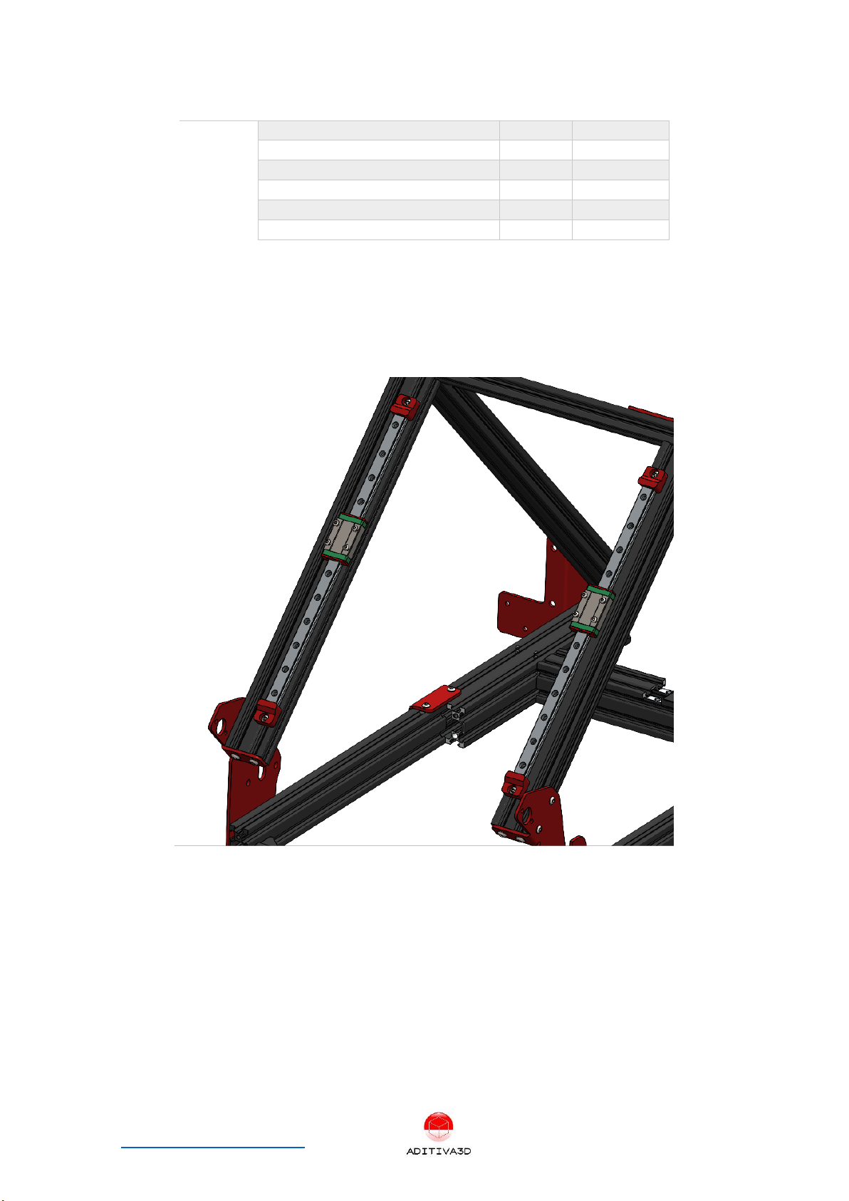
Using 5 units M3x8mm Screws and M3 Slot nuts for each rail, mount it as shown in the
next picture, a distance of 50mm from the bottom of the aluminum bar to the bottom
of the rail should be considered:
Figure 18 Correct position for diagonal rails mounting

Ender 3 Belt Kit ADD-ON assembly manual P a g e 13 | 15
www.belt3dprinterkit.com
Figure 19 50 mm distance to be considered
Using 4 units M4x8mm Screws and M4 Slot nuts install 4 units Rail stops at both ends
of the rails:
Figure 20 Rail stops position
Step 3.5 X axis mounting
Next items from the KIT will be used:
ITEM
ITEM DESCRIPTION
Quantity
Origin
1
Side X axis Bracket P3
2
ADD-ON kit
2
M5x8x37 Aluminum Spacer
6
ADD-ON kit
3
M5x50 mm Screw
6
ADD-ON kit
4
M5 Nylock nut
6
ADD-ON kit

Ender 3 Belt Kit ADD-ON assembly manual P a g e 14 | 15
www.belt3dprinterkit.com
5
M3x8 mm Screw
10
ADD-ON kit
6
M3 Slot nut
10
ADD-ON kit
7
M3x6 mm Screw
8
ADD-ON kit
8
Gt2 Timing belt x 1m
2
ADD-ON kit
9
Nylon Zip ties
8
ADD-ON kit
Using Side X Axis Bracket P3, 3 units M5x8x37 Aluminum Spacer, 3 units M5x50 Screws
and 3 units M5 Nylock nuts per each side, mount the X axis using 4 units M3x6 per side
as shown in the next pictures:
Figure 21 Left side X axis plate mounting
Figure 22 Right side X axis plate mounting
Using supplied Gt2 timing belts, and zip ties install it as shown:
M5x8x37 Spacer

Ender 3 Belt Kit ADD-ON assembly manual P a g e 15 | 15
www.belt3dprinterkit.com
Figure 23 Gt2 timing belt installation
Step 3.6 Faceplate mounting
Using 4 units M4x8 Screws and M4 T-nuts install supplied metal Faceplate at the front
edge of the belt
Figure 24 Faceplate mount
Step 3.7 Wiring
Using supplied Motor wire (1m) connect extruder motor to the extruder port on your
board.
Wire each fan to their corresponding cables originally for the Ender 3 fans (hot-end
and layer fan) soldering might be needed.
Use supplied zip ties for cable management of the extruder harness.
Table of contents
Other ADITIVA 3D 3D Printer manuals


