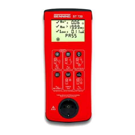
Benning ST 755+ User manual

BENNING ST 755+ / ST 760+
Operating manual
Translation of the German original version
5284 / 08/2023 en

Legal notice
5284 / 08/2023 enBENNING ST 755+ / ST 760+2
Legal notice
Notes concerning the documentation
Ensure that the applicable documentation is used for this product. For safe handling, knowledge
that is provided in these instructions is required.
The product may only be handled while following this documentation, particularly the safety
instructions and warnings it contains. The personnel must be qualified for the respective task
and have the capability to recognise risks and prevent possible dangers.
Manufacturer and holder of rights
BENNING Elektrotechnik und Elektronik GmbH&Co.KG
Münsterstraße135–137
46397 Bocholt
Germany
Phone: +492871/93‑0
E‑mail: [email protected]
Internet: www.benning.de
Commercial register Coesfeld HRAno.4661
Copyright
© 2023, BENNING Elektrotechnik und Elektronik GmbH&Co.KG
All rights reserved.
This document– particularly all of the contents, texts, photographs and graphics that it
contains– are protected by copyright.
No part of this documentation or the associated contents may be reproduced or edited, copied
or distributed using electronic media in any form (printed, photocopied or using any other
method) without express written permission.
Disclaimer
The contents of the documentation has been checked to ensure that it corresponds to the
hardware and software described. Nevertheless, deviations cannot be ruled out, so Benning
cannot guarantee complete correspondence. The contents of this documentation are checked
at regular intervals, and any corrections that are needed are contained in the versions that
follow.
General non-discrimination
Benning is aware of the importance of language with regard to the gender equality and
endeavors to take this into account at all times. To improve readability, we have refrained from
consistently using differentiating formulations.

Table of contents
Table of contents
1 Introduction..............................................................................................................................................10
1.1 Naming convention .............................................................................................................10
1.2 General notes......................................................................................................................11
1.3 History.................................................................................................................................12
1.4 Service & support................................................................................................................12
2 Safety........................................................................................................................................................13
2.1 Warning system ..................................................................................................................13
2.2 Standards applied ...............................................................................................................13
2.3 Symbols used......................................................................................................................14
2.4 Intended use .......................................................................................................................15
2.5 Special types of risks ..........................................................................................................17
3 Scope of delivery.....................................................................................................................................18
4 Transport and storage.............................................................................................................................20
4.1 Packing and transport .........................................................................................................20
4.2 Storage................................................................................................................................20
5 Device description...................................................................................................................................21
5.1 Device structure ..................................................................................................................21
5.2 Type plate ...........................................................................................................................22
5.3 Screen setup.......................................................................................................................23
5.4 Menu structure ....................................................................................................................25
6 General operation....................................................................................................................................27
6.1 Switching the device ON/OFF.............................................................................................27
6.2 Operating elements.............................................................................................................27
6.3 Login ...................................................................................................................................28
6.4 Buttons in the footer............................................................................................................28
6.5 Operating the list view.........................................................................................................29
6.6 Operating the test view .......................................................................................................31
6.7 Operating the Smartmenu..................................................................................................33
7 Functions..................................................................................................................................................34
7.1 Database.............................................................................................................................34
7.2 Backup copies.....................................................................................................................35
7.3 User administration .............................................................................................................36
7.4 Expert settings ....................................................................................................................36
5284 / 08/2023 en BENNING ST 755+ / ST 760+ 3

Table of contents
7.4.1 Customer-specific limits ......................................................................................................36
7.4.2 Customer-specific visual inspection....................................................................................37
7.4.3 Customer-specific test procedures......................................................................................37
7.4.4 Customer-specific device templates ...................................................................................37
7.4.5 Customer-specific templates...............................................................................................38
7.4.6 Update.................................................................................................................................38
7.4.7 Factory settings...................................................................................................................38
7.5 General test procedure ......................................................................................................38
7.5.1 Automatic testing ................................................................................................................39
7.5.2 Manual testing ....................................................................................................................40
7.5.3 Terminology used in test procedures..................................................................................40
7.6 Device information ..............................................................................................................42
7.7 Individual tests ....................................................................................................................42
7.7.1 Protective conductor resistance..........................................................................................42
7.7.2 Insulating resistance ...........................................................................................................43
7.7.3 Protective conductor current ...............................................................................................44
7.7.4 Contact current....................................................................................................................44
7.7.5 Device leakage current (medical electrical devices) ...........................................................44
7.7.6 Patient leakage current (medical electrical devices)...........................................................45
7.7.7 Functional test.....................................................................................................................45
7.7.8 Cable continuity test............................................................................................................46
7.7.9 Safety extra-low voltage......................................................................................................46
7.7.10 Voltage of the welding circuit ..............................................................................................46
7.7.11 Contact current of the welding circuit..................................................................................47
7.7.12 PRCD..................................................................................................................................47
7.7.13 Power distributors ...............................................................................................................48
7.8 Remote control....................................................................................................................48
7.9 Optional accessories...........................................................................................................49
7.9.1 Three-phase testing with the BENNINGMA4....................................................................49
7.9.2 Three-phase testing with the BENNINGMA3....................................................................50
7.9.3 Three-phase testing with the BENNINGMA2-16...............................................................50
7.9.4 Single-phase and three-phase testing with the leakage current clamp...............................51
7.9.5 Barcode scanner (optional).................................................................................................51
7.9.6 RFIDscanner (optional)......................................................................................................53
7.9.7 Printer (optional)..................................................................................................................54
7.9.8 Keyboard (optional).............................................................................................................55
8 Configuration ...........................................................................................................................................56
8.1 Setting the system data.......................................................................................................56
8.2 Setting the device data........................................................................................................58
8.3 Managing the network settings ...........................................................................................58
8.3.1 Establishing a connection via WLAN ..................................................................................59
8.3.2 Establishing a connection via Bluetooth..............................................................................59
8.4 Managing the expert settings..............................................................................................60
8.4.1 Managing customer-specific limits ......................................................................................60
8.4.2 Creating a customer-specific visual inspection ...................................................................61
5284 / 08/2023 enBENNING ST 755+ / ST 760+4

Table of contents
8.4.3 Creating customer-specific test procedures........................................................................61
8.4.4 Managing customer-specific device templates (test sample templates).............................63
8.4.5 Managing templates............................................................................................................63
8.5 Managing a user .................................................................................................................64
8.6 Managing a database..........................................................................................................65
8.6.1 Creating (“New”) and selecting e.g. a database.................................................................65
8.6.2 Managing test samples .......................................................................................................66
8.6.2.1 “Change”, “Copy” and “Delete” using the test sample as an example ................................67
8.7 Zero balance, cable and probe calibration..........................................................................69
8.8 Setting the display, time and language ...............................................................................70
9 Testing......................................................................................................................................................71
9.1 Requirements for tests and measurements ........................................................................71
9.2 Connecting the safety measuring lines ...............................................................................74
9.3 Automatic testing.................................................................................................................76
9.4 Manual testing.....................................................................................................................77
9.5 Individual tests ....................................................................................................................79
9.5.1 Testing the protective conductor resistance........................................................................79
9.5.2 Testing the insulating resistance.........................................................................................80
9.5.3 Testing the protective conductor current.............................................................................83
9.5.4 Testing the contact current..................................................................................................84
9.5.5 Testing the device leakage current .....................................................................................86
9.5.6 Testing the patient leakage current.....................................................................................87
9.5.7 Functional test.....................................................................................................................90
9.5.8 Cable continuity test............................................................................................................91
9.5.9 Testing the safety extra-low voltage....................................................................................92
9.5.10 Testing the voltage of the welding circuit ............................................................................93
9.5.11 Testing the contact current of the welding circuit................................................................94
9.5.12 Testing of PRCDs ...............................................................................................................95
10 Maintenance.............................................................................................................................................96
10.1 Maintenance schedule ........................................................................................................96
10.2 Making the device free of voltage .......................................................................................96
10.3 Cleaning the device.............................................................................................................97
10.4 Calibrating the device..........................................................................................................97
10.5 Installing an update (GUI, firmware) ...................................................................................98
10.6 Recovering the password....................................................................................................99
11 Technical data........................................................................................................................................100
12 Disposal and environmental protection ..............................................................................................101
13 Appendix ................................................................................................................................................102
13.1 Automatic test procedures ................................................................................................102
5284 / 08/2023 en BENNING ST 755+ / ST 760+ 5

Table of contents
13.1.1 Automatic test procedures according to EN50678 (VDE0701) and EN50699 (VDE0702)
..........................................................................................................................................102
13.1.2 Automatic test procedures according to EN62353 (VDE0751-1)....................................105
13.1.3 Automatic test procedures according to EN60974-4 (VDE0544-4).................................106
13.2 Manual test procedures.....................................................................................................107
13.2.1 Manual test procedures according to EN50678 (VDE0701) and EN50699 (VDE0702)
..........................................................................................................................................107
13.2.2 Manual test procedures according to EN62353 (VDE0751-1)........................................108
13.2.3 Manual test procedures according to EN60974-4 (VDE0544‑4).....................................109
13.3 Test standards ..................................................................................................................110
13.4 Factory settings and measured values .............................................................................111
13.4.1 Factory settings and measured values– Protective conductor resistance tests...............111
13.4.2 Factory settings and measured values– Insulating resistance tests................................112
13.4.3 Factory settings and measured values– Current measuring method...............................113
13.4.4 Factory settings and measured values– Functional test..................................................114
13.4.5 Factory settings and measured values– Cable continuity test.........................................114
13.4.6 Factory settings and measured values– Safety extra-low voltage test ............................115
13.4.7 Factory settings and measured values– PRCD test ........................................................115
13.4.8 Factory settings and measured values– Voltage of the welding circuit test.....................116
13.4.9 Factory settings and measured values– Times................................................................116
13.5 Measuring methods...........................................................................................................117
13.6 Remote control..................................................................................................................118
13.6.1 Remotely controlling the device via the PC.......................................................................118
13.6.2 Remotely controlling the device using a smartphone or tablet..........................................119
Index .......................................................................................................................................................120
5284 / 08/2023 enBENNING ST 755+ / ST 760+6

Table of figures
Table of figures
Figure 1 BENNINGST755+/ BENNINGST760+ device structure .............................................................. 21
Figure 2 Type plate (exemplary) ..................................................................................................................... 22
Figure 3 Screen layout.................................................................................................................................... 23
Figure 4 General operation ............................................................................................................................. 29
Figure 5 Test view........................................................................................................................................... 31
Figure 6 BENNINGMA4 ................................................................................................................................ 49
Figure 7 BENNINGMA3 ................................................................................................................................ 50
Figure 8 BENNINGMA2-16........................................................................................................................... 50
Figure 9 BENNINGCM9-1/ BENNINGCM9-2 ............................................................................................ 51
Figure 10Balance/ calibration ......................................................................................................................... 69
Figure 11Device view– jacks .......................................................................................................................... 75
Figure 12Testing the protective conductor resistance (connection diagram exemplary for VDE0701 and
VDE0702, circuit diagram)............................................................................................................... 79
Figure 13Testing the insulating resistance, ClassI (connection diagram exemplary for VDE0701 and
VDE0702, circuit diagram)............................................................................................................... 80
Figure 14Testing the insulating resistance, ClassII (connection diagram exemplary for VDE0701 and
VDE0702, circuit diagram)............................................................................................................... 81
Figure 15Testing the insulating resistance, ClassIII (connection diagram exemplary for VDE0701 and
VDE0702, circuit diagram)............................................................................................................... 82
Figure 16Testing the protective conductor current (connection diagram, circuit diagram) .............................. 83
Figure 17Testing the contact current, ClassI (connection diagram exemplary for VDE0701 and VDE0702,
circuit diagram) ................................................................................................................................ 84
Figure 18Testing the contact current, ClassII (connection diagram exemplary for VDE0701 and
VDE0702, circuit diagram)............................................................................................................... 85
Figure 19Testing the device leakage current (connection diagram for VDE0751-1, circuit diagram)............. 86
Figure 20Testing the patient leakage current, ClassI (connection diagram for VDE0751-1, circuit diagram,
applied parts of typeF) ..................................................................................................................... 88
Figure 21Testing the patient leakage current, ClassII (connection diagram for VDE0751-1, circuit dia-
gram, applied parts of typeF)........................................................................................................... 88
Figure 22Functional test (connection diagram, circuit diagram) ...................................................................... 90
Figure 23Cable continuity test (example: multiple socket, connection diagram, circuit diagram).................... 91
Figure 24Testing the safety extra-low voltage, ClassI (connection diagram, circuit diagram)........................ 92
Figure 25Testing the voltage of the welding circuit (connection diagram, circuit diagram).............................. 93
Figure 26Testing the contact current of the welding circuit (connection diagram, circuit diagram) ................. 94
Figure 27Testing of PRCDs (connection diagram) .......................................................................................... 95
5284 / 08/2023 en BENNING ST 755+ / ST 760+ 7

List of tables
List of tables
Table 1 History............................................................................................................................................... 12
Table 2 Symbols on the device...................................................................................................................... 14
Table 3 General symbols and buttons in the header ..................................................................................... 23
Table 4 Symbols for test sample and protection class in the header ............................................................ 24
Table 5 Menu structure– Main menu ............................................................................................................ 25
Table 6 Menu structure– Settings................................................................................................................. 26
Table 7 Operating the screen ........................................................................................................................ 27
Table 8 Buttons in the footer.......................................................................................................................... 28
Table 9 Operating the list view ...................................................................................................................... 30
Table 10 Status messages .............................................................................................................................. 30
Table 11 Test view buttons.............................................................................................................................. 31
Table 12 “Test result” screen........................................................................................................................... 32
Table 13 Proceeding with the test report ......................................................................................................... 33
Table 14 Smartmenu– Main menu ................................................................................................................ 33
Table 15 Database structure (exemplary) ....................................................................................................... 34
Table 16 Database contents............................................................................................................................ 34
Table 17 Functions of the “Automatic test” ...................................................................................................... 39
Table 18 Leakage current measurement (test standard and protection class) ............................................... 45
Table 19 PRCDtests ....................................................................................................................................... 47
Table 20 Setting options for system data ........................................................................................................ 56
Table 21 Network settings ............................................................................................................................... 58
Table 22 “Test procedure” screen .................................................................................................................. 62
Table 23 How to manage templates ................................................................................................................ 64
Table 24 Functions of the “Databaseadministration” ...................................................................................... 65
Table 25 “Devices” screen............................................................................................................................... 66
Table 26 Display, time and language .............................................................................................................. 70
Table 27 Maintenance schedule...................................................................................................................... 96
Table 28 Technical data .................................................................................................................................. 100
Table 29 Test procedures according to EN50678 (VDE0701) and EN50699 (VDE0702) for ClassI ......... 102
Table 30 Overview of test procedures according to EN50678 (VDE0701) and EN50699 (VDE0702) for
ClassI (1to 16) ................................................................................................................................ 104
Table 31 Overview of test procedures according to EN50678 (VDE0701) and EN50699 (VDE0702) for
ClassI (17to 32) .............................................................................................................................. 104
Table 32 Test procedures according to EN50678 (VDE0701) and EN50699 (VDE0702) for ClassII ........ 104
Table 33 Test procedures according to EN50678 (VDE0701) and EN50699 (VDE0702) for ClassIII ....... 105
Table 34 Overview of test procedures according to EN50678 (VDE0701) and EN50699 (VDE0702) for
ClassII (1to 6)/ ClassIII (1) ............................................................................................................ 105
Table 35 Test procedures according to EN62353 (VDE0751‑1) for ClassI .................................................. 105
Table 36 Test procedures according to EN62353 (VDE0751‑1) for ClassII ................................................. 106
Table 37 Overview of test procedures according to EN62353 (VDE0751‑1) for ClassI (1to 5)/ ClassII
(1to 2) .............................................................................................................................................. 106
Table 38 Test procedures according to EN60974-4 (VDE0544‑4) for ClassI............................................... 106
5284 / 08/2023 enBENNING ST 755+ / ST 760+8

List of tables
Table 39 Test procedures according to EN60974-4 (VDE0544‑4) for ClassII.............................................. 106
Table 40 Overview of test procedures according to EN60974-4 (VDE0544‑4) for ClassI (1to 3)/
ClassII(1) ........................................................................................................................................ 107
Table 41 Manual test procedures according to EN50678 (VDE0701) and EN50699 (VDE0702)............... 107
Table 42 Manual test procedures according to EN62353 (VDE0751-1)........................................................ 108
Table 43 Manual test procedures according to EN60974-4 (VDE0544‑4) .................................................... 109
Table 44 Overview of test standards ............................................................................................................... 110
Table 45 Overview of test steps ...................................................................................................................... 111
Table 46 Factory settings of the limits for protective conductor resistance tests (conductor 5m, 1.5mm2) .. 111
Table 47 Measured values according to measuring specifications– Protective conductor resistance tests... 111
Table 48 Factory settings of the limits for insulating resistance tests.............................................................. 112
Table 49 Measured values according to measuring specifications– Insulating resistance tests.................... 112
Table 50 Factory settings of the limits for protective conductor current test.................................................... 113
Table 51 Factory settings of the limits for contact current test ........................................................................ 113
Table 52 Factory settings of the limits for leakage current test ....................................................................... 113
Table 53 Protective conductor resistance– Alternative leakage current measuring method.......................... 113
Table 54 Measured values according to measuring specifications– Differential current measuring method . 113
Table 55 Measured values according to measuring specifications– Direct current measuring method......... 114
Table 56 Measured values according to measuring specifications– Functional test...................................... 114
Table 57 Factory settings of the limits for cable continuity test ....................................................................... 114
Table 58 Measured values according to measuring specifications– Cable continuity test............................. 114
Table 59 Measured values according to measuring specifications– Safety extra-low voltage test ................ 115
Table 60 Factory settings of the limits for PRCD-AC....................................................................................... 115
Table 61 Factory settings of the limits for PRCD-A und PRCD-F.................................................................... 115
Table 62 Factory settings of the limits for PRCD-B und PRCD-B+ ................................................................. 115
Table 63 Factory settings of the limits for PRCD 2-pin, 3-pin, K, S and S+ .................................................... 115
Table 64 Measured values according to measuring specifications– PRCD ................................................... 115
Table 65 Factory settings of the limits for voltage of the welding circuit test ................................................... 116
Table 66 Measured values according to measuring specifications– Voltage of the welding circuit test......... 116
Table 67 Factory settings of the limits for times .............................................................................................. 116
5284 / 08/2023 en BENNING ST 755+ / ST 760+ 9

1.1 Naming convention
Introduction
5284 / 08/2023 enBENNING ST 755+ / ST 760+10
1 Introduction
The appliance tester BENNINGST755+/ ST760+ described here (in the following only
referred to as “device”) is intended for the safety testing of electrical test samples (DUTs). The
basic versions of the device enable you to perform the following tests and measurements:
Standard Measurement ST755+ ST760+
EN50678
(VDE0701)
Test procedure for electrical devices
after repair
X X
EN50699
(VDE0702)
Test procedure for electrical devices in
case of periodic testing
X X
EN/ IEC62353
(VDE0751‑1)
Periodic testing and tests after repair of
medical electrical devices or systems
X X
EN/ IEC60974‑4
(VDE0544‑4)
Periodic inspection and testing of arc
welding equipment
- X
Further information
https://tms.benning.de/st760plus-st755plus
On the Internet, you will find the following additional information directly at the specified link or
at www.benning.de (product search):
• Operating manual of the device in several languages
• Further information depending on the device (e.g. brochures, technical reports, FAQs)
1.1 Naming convention
Battery
In this operating manual, the term “battery” is used to refer to accumulators.

Introduction
1.2 General notes
5284 / 08/2023 en BENNING ST 755+ / ST 760+ 11
1.2 General notes
Target group
This operating manual is intended for the following groups of people:
• Qualified electricians and electrotechnically trained personnel
Required basic knowledge
To understand these operating manual, you will need general knowledge of testing and
measuring equipment. Moreover, you will need basic knowledge of the following issues:
• General electrical engineering
Purpose of the operating manual
This operating manual describes the device and provides you information about how to handle
it.
Keep this operating manual in a safe place for later use. Read this operating manual before
handling the device and follow the instructions.
NOTE
Disclaimer of liability
Please make sure that any person using the device has read and understood the instructions of
this operating manual before handling the device and that the instructions are adhered to in all
points. Non-observance of this operating manual might result in product damage, property
damage and/or personal injury.
Benning assumes no liability for damage and malfunctions resulting from the failure to observe
the instructions in this operating manual.
The devices are subject to continuous further development. Benning reserves the right to make
changes to the device’s design, configuration and technology. The information in this operating
manual corresponds to the state of technical knowledge at the time of printing. For this reason,
no claims for certain device characteristics can be derived from the contents of this operating
manual.
Information in this operating manual can be changed at any time without prior notice. Benning is
not obligated to make amendments to this operating manual or to keep it up to date.
Direct any technical questions to Technical Support [}page12].
Figures and drawings
This operating manual includes figures and drawings for general illustrative purposes. The
functional possibilities and representations can deviate from the present device.
Test standards
The content of this operating manual is intended to describe the appliance tester and in no way
replaces the currently applicable test standards.

1.3 History
Introduction
5284 / 08/2023 enBENNING ST 755+ / ST 760+12
Trademarks
All trademarks used are the property of their respective owners, even if they are not separately
marked as such.
Declaration of conformity
The declaration of conformity for this device is held by the manufacturer for the responsible
authority. You can request it from Technical Support [}page12].
1.3 History
Release number Amendments
08/2023 • Initial release
Table1: History
1.4 Service & support
Please contact your specialty retailer or the BENNINGServiceCenter for any repair or service
work that might be required.
Technical Support
Please contact our Technicalsupport for technical questions on handling the device.
Phone: +49287193-555
Fax: +49287193‑6555
E-Mail: [email protected]
Internet: www.benning.de
Returns management
Easily and conveniently use the BENNING returns portal for a quick and smooth returns
processing:
https://www.benning.de/service-de/retourenabwicklung.html
Phone: +49287193-554
E-Mail: [email protected]
Return address
BENNING Elektrotechnik und Elektronik GmbH&Co.KG
Retourenmanagement
Robert-Bosch-Str. 20
D- 46397 Bocholt

Safety
2.1 Warning system
5284 / 08/2023 en BENNING ST 755+ / ST 760+ 13
2 Safety
2.1 Warning system
This operating manual contains notes that must be taken into consideration for your personal
safety and in order to avoid injuries and damage to property. Warnings about your personal
safety and to prevent personal injuries are marked with a warning triangle. Warnings on sole
prevention of material damage are shown without a warning triangle. The warnings are shown
in descending order depending on the hazard level as follows.
DANGER
Extremely dangerous situation for humans
If you do not pay attention to this warning, irreversible or deadly injuries will occur.
WARNING
Hazard to humans
If you do not pay attention to this warning, irreversible or deadly injuries could occur.
CAUTION
Minor hazard to humans
If you do not pay attention to this warning, minor or moderate injuries could occur.
NOTICE
Danger to property, not to persons
If you do not pay attention to this warning, material damage could occur.
If multiple hazard levels occur, the warning for the highest respective hazard level will be used.
In addition, a warning about personal injuries can also include a warning about material
damage.
2.2 Standards applied
The device has been built and tested in compliance with the following standards and has left the
factory in perfectly safe condition.
• IEC/ DINEN 60529 (VDE0470‑1)
• IEC/ DINEN61010-1 (VDE0411‑1)
• IEC/ DINEN61010-2‑032 (VDE0411‑2‑032)
• IEC/ DINEN 61010-031 (VDE0411‑031)
• IEC/ DINEN 61326‑1 (VDE0843-20‑1)
• IEC/ DINEN 61557-1 (VDE0413‑1)
• IEC/ DINEN 61557-2 (VDE0413‑2)
• IEC/ DINEN 61557-4 (VDE0413‑4)
• IEC/ DINEN 61557-6 (VDE0413‑6)
• IEC/ DINEN 61557-16 (VDE0413‑16)

2.3 Symbols used
Safety
5284 / 08/2023 enBENNING ST 755+ / ST 760+14
2.3 Symbols used
Symbols on the device
Symbol Meaning
Please observe the information provided in this operating manual in
order to avoid dangers.
Warning of electrical danger! Please observe the information provided
in this operating manual in order to avoid dangers.
CATII Measuring categoryII is applicable to testing and measuring circuits
which are directly connected to user connections (e.g. sockets) of the
low-voltage mains installation.
The device complies with EUdirectives.
The device complies with directives applicable in GreatBritain.
At the end of product life, dispose of the unserviceable device via
appropriate collecting facilities provided in your community.
The device is provided with protective insulation (protection classII).
Please observe the operating manual.
(DC) direct voltage or direct current
(AC) alternating voltage or alternating current
Earth (voltage to earth)
Bluetooth
WLAN
SDmemory card
USBinterface
PC Micro‑USB interface
Network interface
Table2: Symbols on the device

Safety
2.4 Intended use
5284 / 08/2023 en BENNING ST 755+ / ST 760+ 15
2.4 Intended use
Only use the device within the framework of the corresponding technical data. Any operating
conditions that deviate from this shall be considered as improper use. Solely the user of the
device shall be liable for any resulting damage.
Please note the following:
• In case of improper use, the liability and warranty claims become void. Solely the user of the
device shall be liable for any damage resulting from improper use. Uses not complying with
the intended use include e.g.:
– Hardware or software changes without the knowledge and approval of Benning
– Use of components, accessories, spare or replacement parts that have not been
released and approved for the respective application by Benning
– Non-observance, manipulation, changes or misuse of the operating manual or the
instructions and notes contained therein
– Any form of misuse of the device
– Any use other than or beyond that described in this operating manual
• Warranty and liability claims are generally excluded if the damage is the result of force
majeure.
• If any prescribed services are not performed regularly or not on time, according to the
manufacturer’s specifications during the warranty period, a decision about a warranty claim
can only be made once the findings are available.
Direct any questions to Technical Support [}page12].
Using the device
Please observe the following basic obligations when using the device:
• The device may only be used in a technically perfect and safe condition. Always check the
device for damages before using it.
• The personnel must be qualified for the respective task.
• Electrical safety tests of portable electrical equipment can be carried out by competent
persons or qualified electricians. Due to the definitions of the German technical guideline for
operational safety “Competent persons– Specific requirements– Electrical hazards” (TRBS
“Befähigte Personen– Besondere Anforderungen– Elektrische Gefährdungen”), it is no
longer possible to let the testing be carried out only by electrotechnically trained persons.
However, the electrotechnically trained person can take over tasks in a testing team (e.g.
qualified electrician/ electrotechnically trained person) within the framework of periodic tests
and thus support the qualified electrician.
• Observe relevant regulations on occupational safety and health as well as those on
environmental protection.
• The device may only be used inside buildings and in dry environments.
• Do not use the device in potentially explosive environments.
• Use suitable (approved) safety measuring lines.
• Use suitable (approved) safety measuring accessories.
• Operate the display only with your fingers or the rubberised side of the enclosed stylus.
Doing this, do not apply any pressure to the display.
• Use the device only in a TN, TT or IT power supply network [}page56] with a maximum of
230V+15%/ 400V that complies with the applicable safety regulations.
• Connect the device only to a single-phase mains with 230V, 50Hz and a pre-fuse of 16A.
• Do not connect any external voltage to the test socket, to the built-in jacks or the
IECconnector.

2.4 Intended use
Safety
5284 / 08/2023 enBENNING ST 755+ / ST 760+16
• The device is not intended for measurements in electrical installations! The test sample
must be free of external voltage (disconnected from the mains).
• For the testing of test samples with the warning “High leakage current!”, the test must be
carried out by qualified electricians only!
• For device protection and for functional testing, the test voltages are monitored. In case of a
fault, an error will be indicated on the display. Measurement will be interrupted. In case of a
fault current of ≥25mA, the device will be switched off within a period of 100ms to 200ms.
• In order to detect short-circuits and body contacts occurring behind the switch-on elements
(e.g. switch, thermostat, relay) of the test sample, the test sample must be switched on.
• Tap the “Pause” button to interrupt the measurement. During the pause, the test socket
remains live!
WARNING
Dangerous voltage
Danger to life or serious injury is possible due to contact with high electric voltage in case of
incorrect operation.
• Do not touch the bare measuring probe tips of the safety measuring lines or the bare
contacts of the optional alligator clips, Only touch the safety measuring lines in the area
intended for your hands.
• Please note that dangerous testing voltages might be present at the device during insulating
resistance measurement. These might also be applied to the measuring circuit if safety
measuring lines are contacted.
• Connect the safety measuring lines to the correspondingly marked measuring jacks of the
device and check them for tight fit.
• Only use approved safety measuring lines.
• Attach the protective caps to the contact tips of the safety measuring lines (circuits of
overvoltage category CATIII orIV).
• When disconnecting the measuring circuit, first remove the live safety measuring line
(phase) and then the neutral safety measuring line from the measuring point.
Securing the device
If the device is not in a technically perfect and operationally safe condition, safe operation is no
longer guaranteed. Make sure that the following measures are taken:
• Switch off the device.
• Remove the device from the measuring point.
• Secure the device against unintentional operation.
The following characteristics indicate that safe operation is no longer guaranteed:
• The device (housing, connecting cables, plugs or safety measuring lines) shows visible
damage or is damp/wet.
• The insulation of the safety measuring lines is damaged.
• The device does not work properly in compliance with regulations (e.g. errors during
measurements).
• The device shows recognisable consequences of prolonged storage under inadmissible
conditions.
• The device shows recognisable consequences of extraordinary stress due to transport.

Safety
2.5 Special types of risks
5284 / 08/2023 en BENNING ST 755+ / ST 760+ 17
2.5 Special types of risks
DANGER
Bare conductors or main line carriers
Danger to life or serious injury is possible due to contact with high electric voltage when working
with bare conductors or main line carriers.
• Please observe relevant regulations on occupational safety and health.
• If necessary, use appropriate protective equipment.
WARNING
Dangerous voltage
Danger to life or serious injury is possible due to contact with high electric voltage when working
on live components or equipment. Even low voltages from 30V‑AC and 60V‑DC on can be
dangerous to human life!
• Please observe relevant regulations on occupational safety and health.
• If necessary, use appropriate protective equipment.

2.5 Special types of risks
Scope of delivery
5284 / 08/2023 enBENNING ST 755+ / ST 760+18
3 Scope of delivery
The scope of delivery of the device includes the following components:
• 1x appliance tester BENNINGST755+ (item no.: 050332) or appliance tester
BENNINGST760+ (item no.: 050334)
• 1x SDmemory card ≥4GB (item no.: 10003760)
• 2x safety measuring line (black/ red) (item no.: 10173716)
• 1x mains cable (3x1.5mm², l=500mm), shock-proof plug to IECconnector (item
no.:10009127)
• 1x 2m test probe, 2-pin, (black) with 4mm probe tip and double plug-in contact (item
no.:10150829)
• Set of safety measuring lines BENNINGTA1 (item no.: 044124)
Ø 4mm alligator clips, 2‑piece, red/ black, professional version, CATIII 1 000V, 36A
• 1x input stylus for touchscreen operation (item no.: 10009128)
• 1x quick reference guide
Optional accessories
Software:
• PCsoftware BENNINGPC-WinST750-760 (item no.: 047002)
Barcode scanners and labels:
• 1D-USBbarcode scanner for reading 1Dbarcodes (item no.:009369)
• 1D/2Dbarcode scanner with USB for barcodes, QRcodes and DataMatrix codes, (item
number:009373)
• 1D/2Dcordless barcode scanner with Bluetooth® function (item no.:009374)
• PVCbarcode labels with consecutive numbering on rolls (rolls of 1 000pieces) (item
no.:756301), further number ranges available (up to item no.:756310)
RFIDscanner and tags:
• Multi-frequency RFIDscanner for reading out the UIDno., with USBinterface (item
no.:009372)
• RFIDtag, self-adhesive, for attachment onto the housing, diameter: 18mm, PU(packaging
unit)=100tags (item no.: 044156)
• RFIDtag (tag-type), for attachment by means of cable ties, l43mmxw34mm,
PU=100tags (item no.:044158)
Printer, labels and badges:
• Portable label and log printer BENNINGPT2 (item no.:10225404)
• Test badges “nexttest” (300pieces, item no.:756212)
• Label rolls for BENNINGPT2 (item no.:10225408)
• Thermographic paper rolls for BENNINGPT2 (item no.:10225407)
• Thermographic paper refill rolls for BENNINGPT1 (20pieces, item no.:044151)
Test probes:
• 5m test probe, 2-pin, (black) with 4mm probe tip and double plug-in contact (item
no.:10154024)
• 2m test probe, 2-pin, (black) with 4mm probe tip and double plug-in contact (item
no.:10150829)
• Brush probe for gentle contacting of accessible conductive parts (item no.:10217861)

Scope of delivery
2.5 Special types of risks
5284 / 08/2023 en BENNING ST 755+ / ST 760+ 19
Keyboards:
• Industrial keyboard with USBinterface (item no.:044154)
• Wireless keyboard with USBreceiver (item no.:044161)
Leakage current clamp and measuring adapters:
• TRUERMS leakage current clamp BENNINGCM9‑1 (item no.: 044682) or
BENNINGCM9‑2 (item no.: 044685) for measuring leakage current, differential current and
protective conductor current (complies with EN61557‑13, EN61557‑16).
• Measuring adapter for BENNINGCM9‑1/ CM9‑2, for IPE measurements (using the
differential current and direct current measuring method) as well as load current
measurements. The conductors are led through individually and provided with double
insulation:
– 16A CEEcoupling– CEEconnector, 5-pin (item no.:044127)
– 32A CEEcoupling– CEEconnector, 5-pin (item no.:044128)
– Shock-proof plug/ coupling, single-phase (item no.: 044131)
Measuring adapters for single-phase and three-phase loads:
• BENNINGMA4 measuring adapter, (16A CEE 3-pin, 16A/32A CEE 5-pin) for single-
phase/three-phase loads with CEE extension cables (item no.:044162)
• Mains connection cable for BENNINGMA4 measuring adapter, 16A CEEconnector – 32A
CEEcoupling, 5-pin (item no.:044163)
• BENNINGMA3 measuring adapter, (16A CEE 3-pin, 16A/32A CEE 5-pin) for single-
phase/three-phase loads with CEEextension cables (item no.:044159)
• BENNINGMA2‑16 measuring adapter, (16A CEE 3-pin, 16A/32A CEE 5-pin) for three-
phase loads (item no.:044160)
• Measuring adapter 3-fold CEE (16A CEE 3-pin, 16A/32A CEE 5-pin) for single-phase/
three-phase loads (item no.:044147)
• Measuring adapters for single-phase/three-phase loads:
16A CEE coupling (5-pin) – shock-proof plug (item no.:044122)
32A CEE coupling (5-pin) – shock-proof plug (item no.:044123)
16A CEE coupling (3-pin) – shock-proof plug (item no.:044143)
32A CEE coupling (3-pin) – shock-proof plug (item no.:044144)
Third-party software
• PCsoftware “cerhost.exe” for remote control of the device [}page118]
– Direct download:
https://forum.fs-net.de/wcf/index.php?attachment/379-cerhost-zip/
– Download overview (download cerhost.zip only):
https://forum.fs-net.de/index.php?thread/4391-cerhost-display-and-control-your-
windows-ce-device-from-your-desktop/
• “CerHost” app from MicroitElectronicsSRL for remote control of the device [}page118]
You can find the Android™ or iOS™app in the respective app store under the search term
“CerHost”.

4.1 Packing and transport
Transport and storage
5284 / 08/2023 enBENNING ST 755+ / ST 760+20
4 Transport and storage
4.1 Packing and transport
Damage due to improper transport will result in exclusion of liability. Make sure that the
following measures are taken:
• Do not expose the device to shocks.
• If the device has been transported under conditions deviating from the operating
temperature or maximum relative air humidity specified in the Technical data [}page100],
the device needs an acclimatisation phase of at least twohours before being switched on.
• Please keep the original packaging for later dispatch (e.g. for calibration).
• Dispatch the device in its original packaging only. Transport damages due to improper
packaging are excluded from warranty.
If the original packaging is no longer available, you can reorder it from the returns
management [}page12]:
– Outer package (item no.:10043820)
– Moulded parts (item no.:10043821)
4.2 Storage
NOTICE
Improper storage
The device can be damaged due to improper storage.
• Follow the conditions for storage indicated.
Ensure the following measures during storage:
• Close the device case before storing the device.
• Store the device in a suitable location. Storage locations with the following conditions are
recommended:
– Dry and dust-free spaces
– No direct exposure to sunlight
– Keep away from chemical substances
• Do not store the device outdoors without protection.
• Ensure that the values in the technical data [}page100] for the following ambient
conditions are adhered to at the storage location:
– Storage temperature
– Relative humidity (non-condensing)
• Condensation can form if there are large temperature fluctuations. Ensure that the
permissible value of 20K per hour is not exceeded at the storage location.
• For optimum storage, the device case is equipped with an automatic pressure valve near
the carrying handle on the front of the device case.
This manual suits for next models
1
Table of contents
Other Benning Measuring Instrument manuals

Benning
Benning CM 8 User manual

Benning
Benning TA PV User manual

Benning
Benning TRITEST Pro User manual

Benning
Benning duspol expert User manual

Benning
Benning CFlex 1 User manual

Benning
Benning IT 100 User manual

Benning
Benning IT 130 User manual

Benning
Benning Sun 2 User manual

Benning
Benning CM 9-1 User manual

Benning
Benning EV 3-2 User manual

Benning
Benning TA 6 User manual

Benning
Benning Sun 2 User manual

Benning
Benning ST 710 User manual

Benning
Benning VT 2 User manual

Benning
Benning PV 1-1 Manual

Benning
Benning CM 2 User manual

Benning
Benning ST 725 User manual

Benning
Benning CC 4-1 User manual

Benning
Benning CM P1 User manual

Benning
Benning PV 2 Manual