Anritsu 3670 50 Series User manual

The test & measurement
equipment you need at
the price you want.
Alltest carries the world’s largest selection of
used/refurbished benchtop test & measurement
equipment at 50% the price of new.
O
Our equipment is guaranteed working, warrantied, and
available with certified calibration from our in-house staff
of technicians and engineers.
• 10+ full time technicians with over 150 years of
specialization
• 90 day warranty & 5 day right of return on all
equipment
•
• 1-3 year warranties for new and
premium-refurbished equipment
• Every unit tested to OEM specifications
• Satisfaction guaranteed
You have plans, we will help you achieve them.
Any project. Any budget.
Get a quote today!
CCall (732) 919-3339 or email sales@alltest.net.
t
Alltest Instruments, Inc.
500 Central Ave.
Farmingdale, NJ 07727
P: (732) 919-3339
F: (732) 919-3332
alltest.net
s
sales@alltest.net

Anritsu Company
490 Jarvis Drive
Morgan Hill, CA 95037-2809
USA
http://www.anritsu.com
Part Number: 10410-00072
Revision: J
Published: November 2020
Copyright 2019 Anritsu Company. All Rights Reserved.
OPERATION AND MAINTENANCE MANUAL
FOR 3670x50 SERIES SEMI-RIGID CABLES
1. INTRODUCTION
This manual describes the 3670x50 series semi-rigid
cables (Figure 1). It provides specifications,
performance verification instructions, and a list of
precautions the user should observe when using
these cables.
2. DESCRIPTION
The 3670x50 series cables are laboratory quality
cables that contain General Precision Connectors
(GPC).The model number of each cable in the series
is listed in Table 1 with connector type and frequency
range. These cables are used to connect VNA test
sets to the device under test (DUT). They are also
used to connect to a 3680 Universal Test Fixture or
other test interface device.
3. SPECIFICATIONS
Table 1 lists the performance specifications for these
cables.
Figure 1. Typical 3670x50 Series Semi-rigid Cable
1. Two required.
2. These cables replace 1 and 2 ft. cables (3670K50-1,2).
3. This cable replaces 1.5 ft. cable (3670V50-1.5).
K Connector and V Connector are trademarks of the ANRITSU Company.
Table 1. 3670x50 Series Specifications
Model
Length
(Feet)
Frequency
Range (GHz) Connector Type Return Loss
3670N50-1(1) 1DC to 18 Type N Female to Type N Male 17 dB min.
3670N50-2 2
3670NN50-1(1) 1DC to 18 Type N Male to Type N Male 17 dB min.
3670NN50-2 2
3670A50-1(1) 1DC to 18.5 GPC-7 to GPC-7 17 dB min.
3670A50-2 2
3670K50A-1(1),(2) 1DC to 43.5 K Connector™Female to K Connector Male 16 dB min.
3670K50A-2(2) 2
3670V50-1(1) 1DC to 65 V Connector™Female to V Connector Male 16 dB min.
3670V50-2(3) 2
3670V50A-1(1) 1DC to 70 V Connector Female to V Connector Male 16 dB min.
3670V50A-2(3) 2
3670W50-1 10 cm DC to 110 GHz W1 Connector Female to W1 Connector Male 12 dB min.
3670W50-2 16 cm
3670.850-1 10 cm DC to 145 GHz 0.8 mm Connector Female to
0.8 mm Connector Male 10 dB min. (Typ.)
3670.850-2 16 cm

2 PN: 10410-00072 Revision: J 3670x50 Semi-Rigid Cables OMM
4. PRECAUTIONS
ANRITSU series 3670x50 cables are precision
laboratory items and should receive the same care
and respect afforded other such equipment.
Complying with the following precautions will
guarantee longer cable life and less equipment
downtime due to connector failure. Also, such
compliance will ensure that cable component failures
are not due to misuse or abuse—two failure modes
not covered under the ANRITSU warranty.
a. Bend Cables Carefully. Never bend the cable
sharply. Use gentle radius bends only. Place
bends in the center portion of cable; never bend
near the connectors. Avoid twisting cable; loosen
and re-tighten connectors, if necessary.
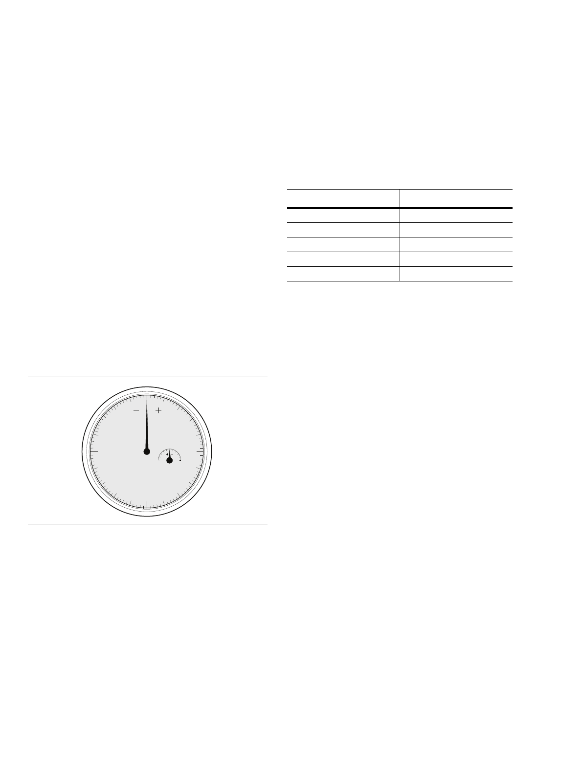
b. Beware of Destructive Pin Depth of Mating
Connectors. Measure the center conductor depth
of DUT connectors that mate with 3670x50 cable
connectors, before mating. Use an ANRITSU
Pin Depth Gauge (Figure 2), or equivalent. Based
on RF components returned for repair, destructive
center conductor depth of mating connectors is
the major cause of failure in the field. When a
3670x50 cable connector is mated with another
connector having a destructive pin depth,
damage will likely occur to the cable connector.
(A destructive pin depth has a center conductor
that is too long in respect to the reference plane of
the connector.)
The center conductor depth of 3670x50 cable
connectors have a tolerance measured in mils
(1/1000 inch). Test device connectors that mate
with these cables may not be precision types and
may not have the proper center conductor depth.
They must be measured before mating to ensure
suitability.
If the test device center conductor is too long, it
will measure out of tolerance in the “+” region
(Table 2). Mating under this condition will
possibly damage the cable center conductor.
If the test device center conductor is too short it
will measure out of tolerance in the “–” region.
This condition will not cause damage; however,
it may result in a poor connection and result in a
degradation of performance.
c. Avoid Over Torquing Connectors. Over
torquing connectors is destructive; it may damage
the connector center pins. Always use a connector
torque wrench when tightening GPC and other
precision type connectors. (The wrench should be
set to 8 inch-pounds maximum.) Never use pliers.
d. Avoid Mechanical Shock. Do not drop or other-
wise treat 3670x50 cables roughly. Mechanical
shock or rough handling will decrease the useful
life of these cables. Avoid introducing a bend
radius of less than 3 inches.
e. Keep Cable Connectors Clean. The precise
geometry of the precision connectors that makes
the high performance of these cables possible can
be easily disturbed by dirt and other contami-
nation adhering to connector interfaces. When not
in use, keep the connectors covered. Refer to
section 7 for cleaning instructions.
5. CONNECTING AND USING CABLES
Connect the female connector of one 3670x50 cable to
the Port 1 connector of the test set. Repeat for Port 2
with the second cable (if used). When connecting
cables, use a connector torque wrench and observe all
other precautions described above.
Figure 2. Pin Depth Gauge Scale
0
1
2
3
4
5
1
2
3
4
2
11
2
Table 2. Allowable Mating Connector Pin Depth
Connector Pin Depth Type (Inches)
GPC-7 +0.000 to –0.003
K +0.000 to –0.005
V +0.000 to –0.004
N Male –0.207 to –0.227
N Female +0.207 to +0.187

3670x50 Semi-Rigid Cables OMM PN: 10410-00072 Revision: J 3
6. PERFORMANCE VERIFICATION
Performance verification consists of measuring the
pin depth of the cable connectors and measuring
return loss of each cable.
a. Pin Depth Measurement. Gauges for measuring
the pin depth of GPC-7, K, and V type connectors
are located in the Model 365X calibration kits
available from ANRITSU. Instructions for using
these gauges are provided with each set. The pin
depth specifications for each cable model are
listed in Table 3.
b. Return Loss Measurement. To measure the
return loss of 3670x50 series cables, proceed as
follows:
1. Perform a reflection only VNA calibration with
the cables disconnected. Use a sliding load
when performing this calibration. (Refer to the
Vector Network Analyzer Operation Manual.)
2. Connect cable to be checked. Terminate cable
with a precision termination (the return loss of
the termination used for this test must be
30 dB or greater).
3. Perform a return loss measurement over the
operating frequency for the cable (see Table 1).
4. Verify that return loss is within specifications
listed in Table 1.
5. Repeat for second cable (if used).
7. MAINTENANCE
It is recommended that no maintenance other than
cleaning be attempted by the customer. Series
3670x50 cables should be returned to ANRITSU for
repair and/or service when needed.
To clean the connector interfaces, follow the
instructions found in the Connector Care Instruction
Sheet (10100-00060).
Table 3. 3670x50 Series Connector Pin Depth
Model Connector Type Pin Depth (Inches)
3670A50
(-1 & -2) GPC-7 –0.0000 to –0.001
3670K50A
(-1 & -2) K Connector®–0.0000 to –0.001
3670V50
(-1 & -2) V Connector®–0.0000 to –0.0040
3670V50A
(-1 & -2) V Connector®–0.0000 to –0.0040
3670N50
(-1 & -2) N Male –0.207 to –0.227
3670NN50
(-1 & -2) N Female 0.207 to 0.187
3670W50
(-1 & -2) W1 Connector 0.000 to -0.003
3670.850
(-1 & -2)
0.8 mm
Connector 0.000 to -0.003

4 PN: 10410-00072 Revision: J 3670x50 Semi-Rigid Cables OMM
This manual suits for next models
16
Table of contents
Other Anritsu Cables And Connectors manuals
Popular Cables And Connectors manuals by other brands

Philips
Philips SWV2212W Specifications

Philips
Philips SWA2519W Specifications

EINHELL
EINHELL BT-BO 16 A LED Original operating instructions

Harbor Freight Tools
Harbor Freight Tools Roadshock LED Light Bar Wiring Kit owner's manual

Radiant
Radiant IDP-115 installation manual

Extron electronics
Extron electronics 13W3-to-VGA Cables and Adapters user guide