BEGA 71 085 User manual

BEGA Gantenbrink-Leuchten KG · Postfach 31 60 · 58689 Menden · info@bega.com · www.bega.com 1/2
06.19 · Technische Änderungen vorbehalten · Technical amendments reserved · Modications techniques réservées
IP 54
!
Anschlusskasten mit Bluetooth-DALI-Gateway
Connection box with Bluetooth DALI gateway
Boîte de connexion avec Passerelle Bluetooth-DALI
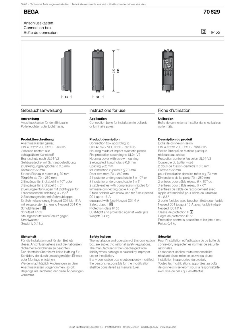
71 085
8080 7575
250250
237237
N
L1
L2
L3 PE
L
D
D
Reset
DALI-LEDs
Bluetooth-LEDs
Gebrauchsanweisung Instructions for use Fiche d’utilisation
Anwendung
Anschlusskasten mit Bluetooth-DALI-Gateway
für den Einbau in Lichtmaste und für die
Verwendung im modularen
LED-Pollerleuchtensystem.
Das Bluetooth-DALI-Gateway ermöglicht
die Einrichtung und Verwaltung einer DALI-
Anlage per Smartphone oder Tablet über die
kostenlose App BEGA Tool.
Application
Cable connection box with Bluetooth DALI
gateway for installation in luminaire poles and
for usage in the modular LED bollard concept.
The Bluetooth DALI gateway allows the
installation and management of a DALI system
by smartphone or tablet PC using the free
BEGA Tool app.
Utilisation
Boîte de connexion avec Passerelle Bluetooth-
DALI à installer dans le mâts et pour utilisation
dans ce nouveau concept modulaire du balise
à LED.
La passerelle Bluetooth-DALI permet
l’installation et la gestion d’une installation
DALI avec un smartphone ou une tablette via
l’application gratuite BEGA Tool.
Produktbeschreibung
Anschlusskasten gemäß
DIN VDE 0660 · Teil 505 und DIN 43628
Gehäuse besteht aus
schlagzähem Kunststoff
Brandschutz nach UL94-V2
Gehäusedeckel mit Schraubbefestigung
2 Befestigungslanglöcher ø6,5 mm
Abstand 237mm
für den Einbau in Maste ø > 110mm
Türgröße ab 85 x 250mm
2 Kabeleinführungen mit zweiteiliger
Schaumstoffdichtung für Erdkabel 3 x 1,5@
bis max. 7 x 6@
Klemmenbelegung L1· L2 · L3 · N · PE
2 Anschlussklemmen zum Anschluss von
Datenadern · D
2 Leitungseinführungen mit Dichtnippel für
Leuchtenanschlussleitung 5x1,5@
oder
2 Leitungseinführungen mit Doppel-Dichtnippel
für 4 Leuchtenanschlussleitungen 3x1@
Sicherungsklemme mit Feinsicherung
6,3 A träge ø 5 ×20 mm
Bis zu 64DALI-Betriebsgeräte können in eine
Anlage integriert und in Gruppen und Szenen
verwendet werden
DALI-Ausgangsspannungsbereich: 14-18 V DC
maximaler Ausgangsstrom: 250mA
garantierter Ausgangsstrom: 150mA
Leistungsaufnahme: 0,75-6 W
(je nach Teilnehmerzahl am Bus)
Bluetooth 5.0
Funkfrequenz 2,4 GHz
Betriebstemperatur: -40 °C bis 60 °C
Schutzart IP 54
Staubgeschützt und Schutz gegen
Spritzwasser
c – Konformitätszeichen
Gewicht: 0,45 kg
Product description
Connection box according to
DIN VDE 0660 · Teil 505 and DIN 43628
Housing made of impact-resistant synthetic
material
Fire protection according to UL94-V2
Housing cover with screw mounting
2 elongated xing holes ø 6.5 mm
Spacing 237mm
for installation in poles ø > 110mm
Door size from 85 x 250mm
2 cable entries with two-part foam gasket
for underground cable 3 x 1,5@
of up to max. 7 x 6@
Terminal connection L1· L2 · L3 · N · PE
2 connecting terminals for connecting data
wires · D
2 cable entries with compression nipples
for luminaire connecting cable 5x1,5@
or
2 cable entries with double compression
nipples for 4 luminaire connecting cables 3x1@
Fuse terminal with micro fuse
6,3 A slow ø 5 ×20 mm
Up to 64DALI operating devices can be
integrated in one system and used in groups
and scenarios
DALI output voltage range: 14-18 V DC
Maximum output current: 250mA
Guaranteed output current: 150mA
Power consumption:0,75-6 W
(depending on the the number of participants
at the bus)
Bluetooth 5.0
Radio frequency 2.4GHz
Operating temperature: -40 °C bis 60 °C
Protection class IP 54
Protection against harmful dust deposits and
splash water
c – Conformity mark
Weight: 0.45 kg
Description du produit
Boîte de connexion selon
DIN VDE 0660 · Teil 505 et DIN 43628
Boîtier fabriqué en matière plastique
résistant aux chocs
Protection contre le feu selon UL94-V2
Couvercle du boîtier à vis
2 trous de xation diamètre ø 6,5 mm
Entraxe 237mm
pour l’installation dans les mâts ø > 110mm
Dimensions de la porte 85 x 250mm
2 entrées de câble avec joint en mousse
en deux parties pour câble souterrain 3 x 1,5@
max. 7 x 6@
Disposition de bornes L1· L2 · L3 · N · PE
2 bornes pour le raccordement du l de
données · D
2 entrées de câble de raccordement
avec double nipple d’étanchéité
pour câble du luminaire 5x1,5@
ou
2 entrées de câble de raccordement
avec nipple d’étanchéité
pour 4 câbles du luminaire 3x1@
Porte fusible avec fusible à l n
6,3 A lent ø 5 ×20 mm
Jusqu’à 64systèmes de commande DALI
peuvent être intégrés à une installation et
utilisés en scénarios et en groupe
Plage de tension de sortie DALI: 14-18 V DC
Courant de sortie maximal: 250mA
Courant de sortie garanti: 150mA
Puissance absorbée :0,75-6 W
(selon le nombre d'abonnés au bus)
Bluetooth 5.0
Fréquence radio 2,4 GHz
Température de service: -40 °C bis 60 °C
Degré de protection IP 54
Protection contre la poussière et les projections
d’eau
c – Sigle de conformité
Poids: 0,45 kg

BEGA Gantenbrink-Leuchten KG · Postfach 31 60 · 58689 Menden · info@bega.com · www.bega.com
2/2
Sicherheit
Für die Installation und für den Betrieb
dieses Anschlusskastens sind die nationalen
Sicherheitsvorschriften zu beachten.
Die Montage und Inbetriebnahme darf nur
durch eine elektrotechnische Fachkraft
erfolgen.
Der Hersteller übernimmt keine Haftung für
Schäden, die durch unsachgemäßen Einsatz
oder Montage entstehen.
Werden nachträglich Änderungen an dem
Anschlusskasten vorgenommen, so gilt
derjenige als Hersteller, der diese Änderungen
vornimmt.
Safety indices
The installation and operation of this connection
box are subject to national safety regulations.
Installation and commissioning may only be
carried out by a qualied electrician.
The manufacturer is then discharged from
liability when damage is caused by improper
use or installation.
If any connection box is subsequently modied,
the persons responsible for the modication
shall be considered as manufacturer.
Sécurité
Pour l’installation et l’utilisation de ce boîte de
connexion, respecter les normes de sécurité
nationales.
L’installation et la mise en service ne doivent
être effectuées que par un électricien agréé.
Le fabricant décline toute responsabilité
résultant d'une mise en œuvre ou d'une
installation inappropriée du produit.
Toutes les modications apportées au boîte
de connexion se feront sous la responsabilité
exclusive de celui qui les effectue.
EU-Konformitätserklärung
Die BEGA Gantenbrink-Leuchten KG erklärt
hiermit, dass der Funkanlagentyp 71 085 der
Richtlinie 2014/53/EU entspricht.
Der vollständige Text der
EU-Konformitätserklärung ist unter der
folgenden Internetadresse verfügbar:
https://www.bega.com/conf/de/71085
EU Declaration of Conformity
Hereby, BEGA Gantenbrink-Leuchten KG
declares that the radio equipment type 71 085
is in compliance with Directive 2014/53/EU.
The full text of the EU declaration of conformity
is available at the following internet address:
https://www.bega.com/conf/en/71085
Declaration UE de Conformite
Le BEGA Gantenbrink-Leuchten KG, déclare
que l’équipement radioélectrique du type
71 085 est conforme à la directive
2014/53/UE.
Le texte complet de la déclaration UE de
conformité est disponible à l’adresse internet
suivante: https://www.bega.com/conf/fr/71085
Montage
Schraube lösen und Gehäusedeckel
abnehmen.
Befestigungsschrauben der Kabelschelle lösen
und Schellenoberteil mit Dichtungseinsatz
herausnehmen.
Dichtungseinsätze entsprechend der Anzahl
und des Durchmessers der Zugangskabel
anpassen.
Zugangskabel abisolieren und so einlegen,
dass der Außenmantel mindestens 5 mm in
den Anschlusskasten hineinragt.
Kabelschelle montieren.
Schutzleiterverbindung herstellen und
elektrischen Anschluss vornehmen.
Leuchtenanschlussleitung durch den oberen
Dichtnippel in den Anschlusskasten einführen.
Der Anschluss der Leuchte erfolgt an
der Schutzleiterklemme PE sowie den
Anschlussklemmen L (Sicherungssymbol),
N und D, D.
Dabei auf phasenrichtigen Anschluss von
Lund Nachten!
Zur Inbetriebnahme wird ein Smartphone mit
der App BEGA-Tool benötigt.
Um im Fehlerfall das Gateway zurückzusetzen,
muss die untenliegende Reset-Taste für länger
als 3Sekunden gedrückt gehalten werden
(LEDs blinken anschließend 3x auf).
Um auf Werkseinstellung zurückzusetzen, muss
die Reset-Taste mindestens 10Sekunden lang
gedrückt werden (LEDs blinken 5x auf).
Anschlusskasten schließen.
Installation
Undo screw and remove housing cover.
Undo xing screws of the cable clamp and
take out upper part of cable clamp with gasket
insert.
Adapt gasket according to the number and
diameter of the mains supply cables.
Strip mains supply cable and insert it in such
a way that the cable sheathing is led at least
5 mm into the connection box.
Assemble cable clamp.
Make earth conductor connection and electrical
connection.
Lead the luminaire connecting cable through
the compression nipple into the connection
box.
The luminaire is connected to the protective
earthing terminal PE and to the connection
terminals L (fuse icon), N and D, D.
Make the electrical connections at L, N and
DA/DA. Ensure in-phase connection
of Land N!
A smartphone with the BEGA Tool app is
required for commissioning.
In order to reset the gateway in the event of a
fault, the bottom pushbutton (Reset) must be
pressed for longer than 3seconds
(LEDs ash 3x).
In order to reset the system to factory settings,
the pushbutton (Reset) must be pressed for
longer than 10seconds (LEDs ash 5x).
Close the connection box.
Installation
Desserrer la vis et ôter le couvercle.
Desserrer la vis de xation du collier de câble et
retirer la partie supérieure du collier avec l'insert
de joints.
Ajuster le joints de la quantité et diamètre des
câbles d'accés.
Dénuder le câble d'accés et l'insérer de façon
que la gaine extérieure entre de minimum 5 mm
dans la boîte de connexion.
Installer le collier du câble.
Mettre à la terre et procéder au raccordement
électrique.
Introduire le câble de luminaire dans la boîte
de connexion à travers le nipple d'étanchéité
supérieure.
Le raccordement des luminaires se fait au
bornier de mise à la terre PE et aux borniers L
(symbole de protection), N et D, D.
Veiller au bon raccordement électrique:
L(phase) et N (neutre)!
La mise en service nécessite un smartphone
doté de l’application BEGA-Tool.
Pour réinitialiser la pasarelle en cas d’erreur,
maintenir la touche (Reset) inférieure enfoncée
pendant plus de 3secondes
(les LED clignotent 3x).
Pour rétablir les paramètres d’usine,
maintenir la touche enfoncée pendant plus de
10secondes (les LED clignotent 5x).
Fermer la boîte de connexion.
Other BEGA Cables And Connectors manuals
Popular Cables And Connectors manuals by other brands

Fenix
Fenix MPSV 15 installation manual

Tesla
Tesla HPWC installation manual

GAMERON
GAMERON LUXURY TV CABLE instruction manual

molex
molex Milli-Grid Dual row 87568 Series operating instructions

Burndy
Burndy Continental Industries thermOweld CRE-7 instructions

Chauvet DJ
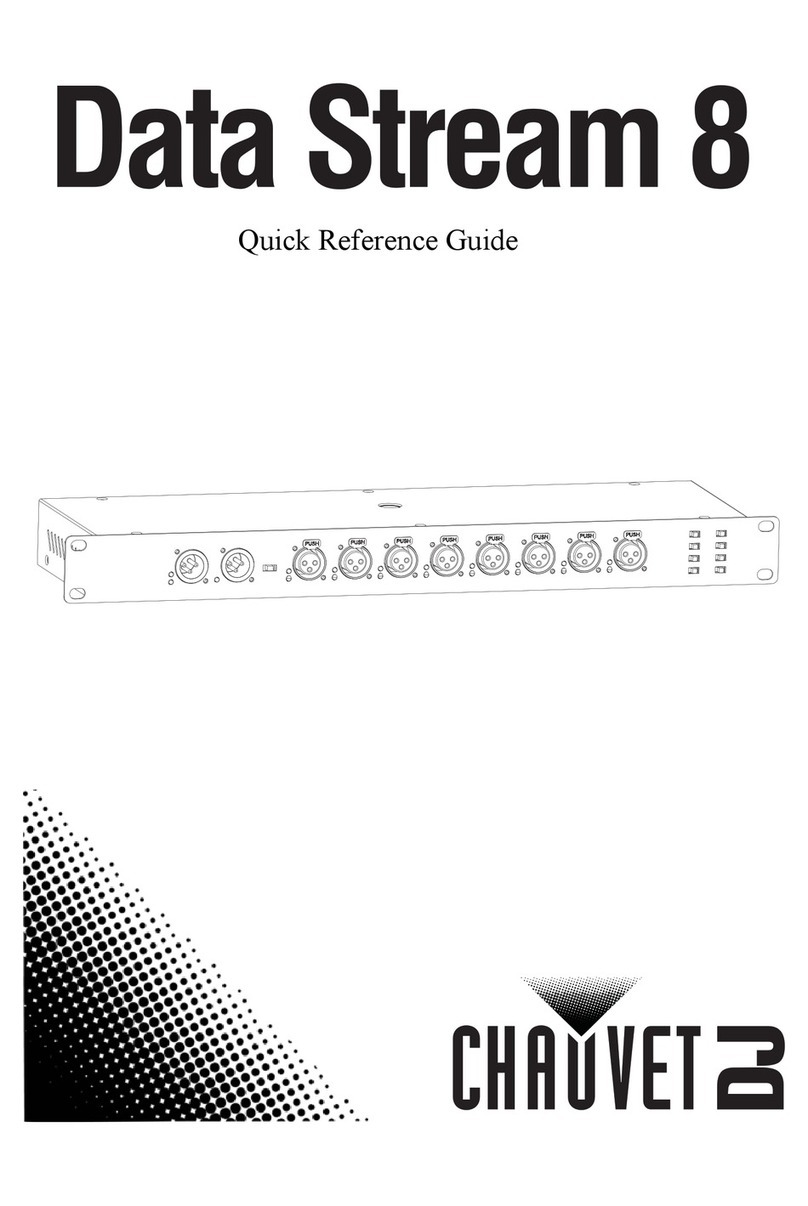
Chauvet DJ Data Stream 8 Quick reference guide


