Anschutz 101-533.NG001 Operating manual

Anschütz GmbH
Zeyestr. 16-24
24106 Kiel
Germany
www.anschuetz.com
Feedback Signal Converter AS
Operator and Service Manual
Type: 101-533.NG001
Edition: 001
10000001298

Copyright
Dieses Dokument sowie dessen Inhalt sind urheberrechtlich
geschützt. Die Weitergabe,Vervielfältigung und Speicherung sowie
die Übersetzung wie auch Verwendung dieses Dokuments oder
dessen Inhalts, als Ganzes oder in Teilen und egal in welcher Form
ist ohne vorherige ausdrückliche schriftliche Genehmigung nicht
gestattet. Zuwiderhandlungen verpflichten zu Schadenersatz.
This document and its content are copyright protected. Distribution,
reproduction and storage as well as translation and exploitation of
this document and its content, in whole or in parts and regardless of
what form, are prohibited without prior express written permission.
Offenders will be held liable for the payment of damages.
Änderungen dieses Dokuments und dessen Inhalt bleiben vorbehal-
ten.
Changes and modification to this document and its content re-
served.

Feedback Signal Converter AS
Table of Contents
Edition: 001 I 10000001298
Table of Contents
List of Figures......................................................................................................................................................III
List of Tables........................................................................................................................................................ V
List of Abbreviations......................................................................................................................................... VII
Introduction........................................................................................................................................................ 1
Preliminary Remarks..................................................................................................................................... 1
Change History..............................................................................................................................................1
Safety.............................................................................................................................................................1
General Safety Regulations.....................................................................................................................1
General Safety Instructions..................................................................................................................... 2
Electrostatic Discharge............................................................................................................................ 2
List of Further Documents.............................................................................................................................3
List of Annex Documents..............................................................................................................................3
1 Description....................................................................................................................................................... 4
1.1 Purpose.....................................................................................................................................................4
1.2 Technical Data..........................................................................................................................................4
1.2.1 Technical Data................................................................................................................................. 4
1.2.2 Electrical Data of CAN Bus Module................................................................................................4
1.2.3 Cable Lengths and Diameters.........................................................................................................4
1.3 Technical Description............................................................................................................................... 5
1.3.1 CAN Bus Module.............................................................................................................................5
1.3.1.1 CAN Bus Technology............................................................................................................. 5
1.4 Functional Description.............................................................................................................................. 7
1.4.1 CAN Bus Module.............................................................................................................................7
1.5 Dependence on Peripheral Systems / Devices........................................................................................7
2 Operation.......................................................................................................................................................... 8
2.1 Preliminary Remarks................................................................................................................................ 8
2.2 Safety Instructions for Operation............................................................................................................. 8
2.3 Pre-Operation Procedures after Longer Time Setting out of Operation.................................................. 9
2.4 Operation.................................................................................................................................................. 9
2.5 Emergency Operation Procedures...........................................................................................................9
2.6 Setting out of Operation...........................................................................................................................9
2.6.1 Procedures for Longer Time Setting out of Operation....................................................................9
3 Installation and Maintenance....................................................................................................................... 10
3.1 Safety Instructions for Installation and Maintenance............................................................................. 10
3.2 General Information................................................................................................................................10
3.2.1 Reference to ISPC.........................................................................................................................10
3.2.2 Special Tools, Measurement and Test Equipment....................................................................... 11
3.2.3 List of Consumables...................................................................................................................... 11
3.3 Installation...............................................................................................................................................11
3.3.1 Installation Procedures.................................................................................................................. 11
3.3.1.1 Install Feedback Signal Converter AS..................................................................................11
3.3.2 Configuration of CAN Bus Module................................................................................................ 11
3.3.3 Cable Connections.........................................................................................................................12

Feedback Signal Converter AS
Table of Contents
10000001298 II Edition: 001
3.3.3.1 General Remarks about Preparing Cable Connections....................................................... 12
3.3.3.2 General Remarks about Preparing Common Ground Connections..................................... 14
3.3.3.3 CAN Bus Module / Service Tool Connections.................................................................... 14
3.4 Care and Maintenance...........................................................................................................................16
3.5 Maintenance and Repair........................................................................................................................ 16
4 Transport and Storage..................................................................................................................................17
4.1 Preservation, Packing and Storage....................................................................................................... 17
4.2 Transport.................................................................................................................................................18
5 Disposal..........................................................................................................................................................19
6 Spare Parts Catalog......................................................................................................................................20
6.1 General Remarks................................................................................................................................... 20
6.2 Definitions............................................................................................................................................... 20
6.3 Feedback Signal Converter AS..............................................................................................................20
7 Annex.............................................................................................................................................................. 21

Feedback Signal Converter AS
List of Figures
Edition: 001 III 10000001298
List of Figures
Fig. 1: Electrostatic Discharge, Protected Area..................................................................................................... 2
Fig. 2: CAN Bus Module, Connections and Indicators...........................................................................................5
Fig. 3: CAN Bus, Jumper for Termination..............................................................................................................6
Fig. 4: Prepare a Cable Connection.....................................................................................................................12
Fig. 5: Prepare a Cable Entry.............................................................................................................................. 13
Fig. 6: Example for Cable Connections............................................................................................................... 13
Fig. 7: Prepare a Common Ground Connection.................................................................................................. 14
Fig. 8: CAN Bus Module, Connections................................................................................................................ 15

Feedback Signal Converter AS
List of Figures
10000001298 IV Edition: 001

Feedback Signal Converter AS
List of Tables
Edition: 001 V 10000001298
List of Tables
Tab. 1: Change History...........................................................................................................................................1
Tab. 2: List of Further Documents......................................................................................................................... 3
Tab. 3: Dimensional Drawings................................................................................................................................3
Tab. 4: Wiring Drawings......................................................................................................................................... 3
Tab. 5: CAN Bus, Cable Requirements................................................................................................................. 6

Feedback Signal Converter AS
List of Tables
10000001298 VI Edition: 001

Feedback Signal Converter AS
List of Abbreviations
Edition: 001 VII 10000001298
List of Abbreviations
EPA ESD Protected Area
ESD Electrostatic Discharge
FU Follow-Up
ISPC Illustrated Spare Parts Catalog
NFU Non-Follow-Up
PCB Printed Circuit Board
RAI Rudder Angle Indicator

Feedback Signal Converter AS
List of Abbreviations
10000001298 VIII Edition: 001

Feedback Signal Converter AS
Introduction
Edition: 001 1 10000001298
Introduction
Preliminary Remarks
The present manual is a description and reference book only. It is intended to answer
questions and to solve problems in the quickest possible manner.
Read and follow the instructions and notes in this manual before operating the equipment.
For this purpose, refer to the table of contents and read the corresponding chapters
thoroughly.
If you have any further questions, contact us under the following address:
Anschütz GmbH Tel. +49 431 / 3019 - 0
Zeyestr. 16 - 24
24106 Kiel Email: [email protected]
Germany www.anschuetz.com
All rights reserved. It is not allowed to copy any part of this manual, neither mechanically,
electronically, magnetically, manually nor otherwise. It is not allowed to store it in a
database, or distribute or forward it without written permission of Anschütz GmbH.
Copyright:
Anschütz GmbH
Zeyestr. 16 - 24
24106 Kiel
Germany
Errors can hardly be avoided in the documentation despite all efforts. Therefore, we
appreciate any remarks and suggestions.
Subject to alterations.
Change History
Tab. 1: Change History
Change Remarks
Edition: 001 Replaces document 4009
Safety
General Safety Regulations
The following safety symbols are used in this manual:
Feedback Signal Converter AS
Introduction
10000001298 2 Edition: 001
WARNING!
Warning statements indicate a hazardous situation that, if not avoided,
could result in minor, moderate or serious injury, or death
Consequence
• Preventive action
CAUTION!
Caution statements indicate a hazardous situation that, if not avoided,
could result in material damage
Consequence
• Preventive action
Note
Notes indicate information considered important but not hazard-related.
General Safety Instructions
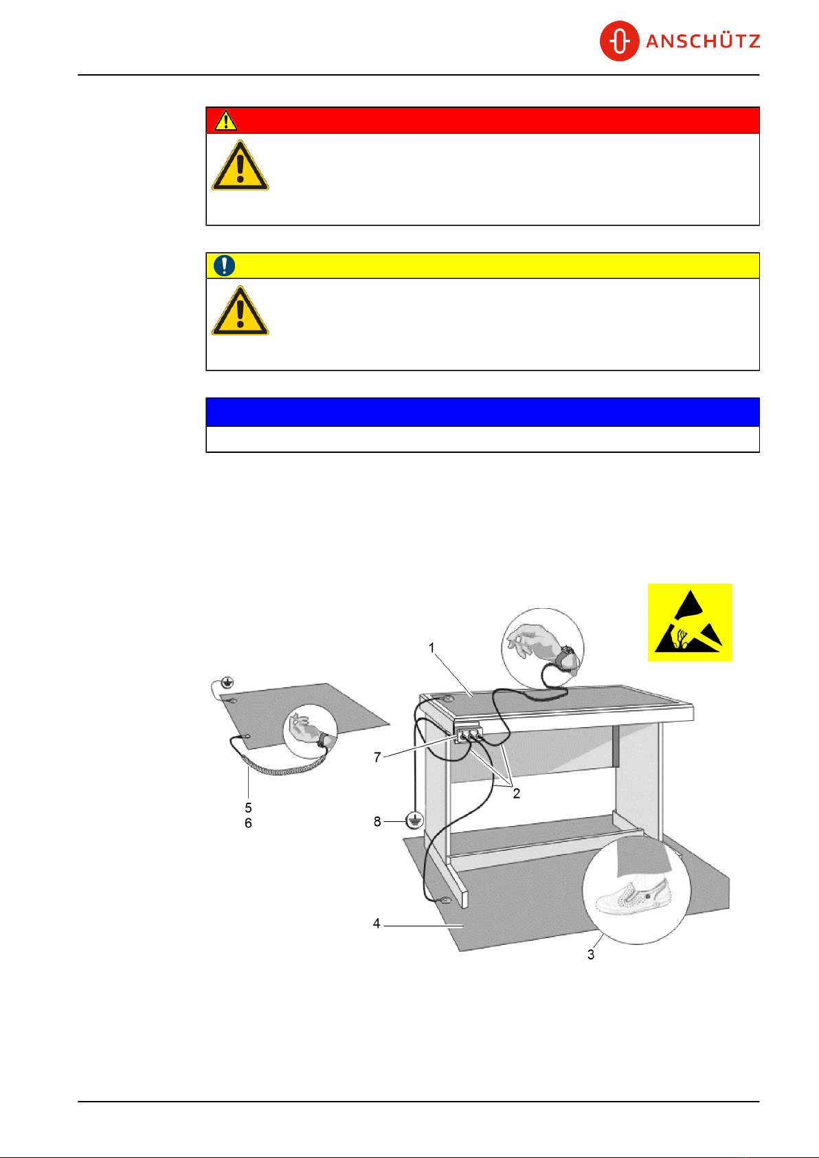
Electrostatic Discharge
Fig. 1: Electrostatic Discharge, Protected Area
1 Table Mat
2 Ground Cord

Feedback Signal Converter AS
Introduction
Edition: 001 3 10000001298
3 Dissipative Shoes
4 Floor Mat
5 Wrist Band
6 Wrist Strap
7 Common Ground
8 Ground Point
Any product which is labeled as shown is electrostatic sensitive.
If proper Electrostatic Discharge (ESD) precautions are not taken, handling or working on
this product results in damage. Every action must be done under ESD protection.
The product and all electronic parts of the product are susceptible to ESD. The product
must be handled with ESD protection especially when removing the covers, touching the
connectors or handling the product components.
All ESD sensitive parts must be packed in metallized protective bags during shipping and
handling outside any ESD Protected Area (EPA). ESD protected spare parts packages
must not be opened / closed out of an EPA.
All necessary equipment for these protective measures can be supplied (on special order)
by Anschütz.
List of Further Documents
Tab. 2: List of Further Documents
Documentation No. Designation
3963 Service Tool AS NB42-232
List of Annex Documents
Tab. 3: Dimensional Drawings
Drawing No. Designation
101-533.HP005 Feedback Signal Converter AS Dimensional Drawing
Tab. 4: Wiring Drawings
Drawing No. Designation
101-533.HP008 Feedback Signal Converter AS

Feedback Signal Converter AS
1 Description
10000001298 4 Edition: 001
1 Description
1.1 Purpose
The Feedback Signal Converter AS is a part of the control loop of a steering control
system. It provides information about the current position of the rudder. This information
is required for follow-up steering, rudder angle indicators, steering failure sensors and
adaptive autopilots which are connected to a bus.
The Feedback Signal Converter AS contains a CAN bus module to convert analog
feedback voltages (actual rudder information) into CAN bus data format.
1.2 Technical Data
1.2.1 Technical Data
Height 100 mm
Width 160 mmDimensions
Depth 80 mm
Weight Approx. 1.5 kg
Protection Class IP 56
Voltage Supply 24 V DC / 1 W
Operation Temperature -15 °C to +55 °C
Compass Safe Distance Standard 0.70 mm, steering 0.45 mm
1.2.2 Electrical Data of CAN Bus Module
Allowed for potentiometer or contactless sensor applications.
Input Voltage 24 V DC / 1 W
CAN bus according to specification 125 kBit/sec
Cycle time 5 msec
Output Absolute rudder position scaled in degrees
(single CAN bus protocol)
1.2.3 Cable Lengths and Diameters
Status lines 12 mm
Power lines 1,52 mm
Potentiometer 3 x 1.52 mm, screened (max. 100 meters)
Feedback Signal Converter AS
1 Description
Edition: 001 5 10000001298
1.3 Technical Description
1.3.1 CAN Bus Module
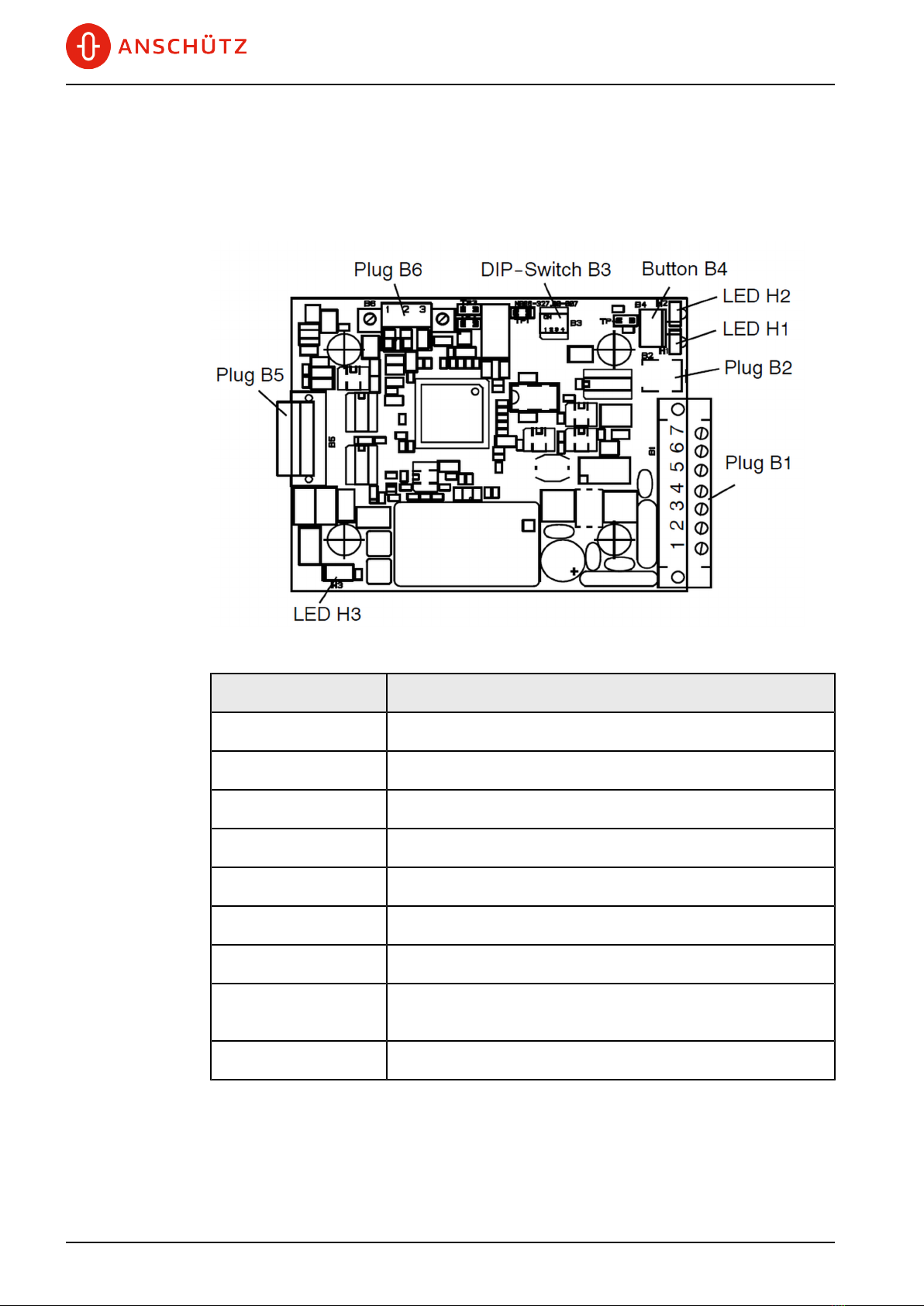
Fig. 2: CAN Bus Module, Connections and Indicators
Element Remarks
Plug B1 Connects CAN bus and supply voltage
Plug B2 Development only
DIP switch B3 Development only (all switches in position ON - do not use.)
Pushbutton B4 Resets CPU
Plug B5 Development only
Plug B6 Rudder position data from potentiometer or contactless sensor
LED H1 Flashes (yellow) if there is no fault
LED H2 Flashes (yellow) if rudder exceeds scaling (1 sec), flashes if
there is fault at the PCB (200 msec)
LED H3 Lights up (red) on PCB failure
1.3.1.1 CAN Bus Technology
The bus is a multi-master bus allowing the connection of all devices and systems
regardless of their tasks and functions. This means that any number of devices can be
connected. These devices must be designed for CAN bus technology.

Feedback Signal Converter AS
1 Description
10000001298 6 Edition: 001
For the CAN bus it is essential that every CAN bus participant is addressable via a
unique address. This address is set within each CAN bus participant or via a component
(participant) which is able to look into the CAN bus architecture.
Note
The CAN bus address can be set with a special service tool by the service personnel only.
It cannot be changed without the service tool.
Each CAN bus participant can send and receive data via the CAN bus. For data
transmission the data is combined with a header (address from the data source), a
heartbeat and the data itself. The data is transmitted to the CAN bus cyclically. Each CAN
bus participant monitors the CAN bus to take off the relevant data.
The CAN bus must be terminated at both ends (within an application) via an ohmic resistor
(120 Ω). The terminating resistor is set by the jumpers at the respective connection, see
Fig. 3.
The termination has to be set between the termination terminals (T) and the CAN low
terminal (L).
Note
2 CAN bus layout options are possible in an application:
• Single CAN bus
• Dual CAN bus
The difference between a single CAN bus and a dual CAN bus application is a CAN bus
redundancy.
In most cases the single CAN bus is duplicated for redundancy, but this feature is for a
redundancy of the respective device not for the CAN bus itself.
Fig. 3: CAN Bus, Jumper for Termination
4 CAN bus termination (T)
5 CAN bus low (L)
The minimum cable requirements for the CAN bus are:
Tab. 5: CAN Bus, Cable Requirements
Term Designation
Type 2 x 2 x 0.75 mm2, screened, twisted pair (twisted pitch length
< 80 mm)
Impedance 120 Ω ± 10 %

Feedback Signal Converter AS
1 Description
Edition: 001 7 10000001298
Term Designation
Capacitance max. 50 pF/m
Cable line delay max. 5 ns/m
Cable length max. 400 m (termination to termination)
1.4 Functional Description
1.4.1 CAN Bus Module
The CAN bus module is set up for potentiometers or contactless sensors.
This has to be configured with a Service Tool (Anschütz service personnel only) for the
specific application.
1.5 Dependence on Peripheral Systems / Devices
Feedback Signal Converter AS is a component of the modular NautoSteer AS steering
control system. Its CAN bus technology, see chapter 1.3.1.1, allows the integration of
various components providing an easy selection of different steering modes and steering
control positions.
NautoSteer AS consists of the following components:
• NFU Tiller Direct
• NFU Tiller AS
• FU Tiller AS
• FU Handwheel AS
• Override Signal Unit AS
• Take Over Operator Unit AS
• Rudder Mode Operator Unit AS
• Steering Mode Operator Unit AS
• Steering Mode Selector Switch AS
• CAN Bus Distribution Unit AS
• CAN Bus Gateway AS
• Rudder Feedback Unit AS
• FU Amplifier AS
• FU Amplifier Proportional AS
• Alarm Signal Unit AS
• Alarm Status Interface AS
• External Steering Interface AS
• Rudder Angle Indicator Equipment
Please refer to the manual of the respective component for detailed information.
Feedback Signal Converter AS
2 Operation
10000001298 8 Edition: 001
2 Operation
2.1 Preliminary Remarks
User Rights
The manual is a complete documentation of the system or equipment. Some functions may
not be accessible depending on user rights.
All functions or operations are described irrespective of the actual user rights of the user.
Markup Elements
The manual uses different markup elements for hardware and software.
Markup Element Description
Bold
This markup is used for the following elements:
• Pushbuttons / Switches
• Softkeys
• Labeling
• Defined areas
Italic
This markup is used for the following elements:
• Menus
• Dialogs
2.2 Safety Instructions for Operation
WARNING!
Danger due to improper operation and use for other than the intended
purpose
Risk of serious injury and material damage
• Use the product only for the intended purpose.
• The system must not be used for navigation.
• Perform operation steps according to this manual.
• Do not make any product modifications without authorization.
WARNING!
Danger due to operation by unskilled personnel
Risk of serious injury and material damage
• Keep all unskilled personnel away from the operation area.
• Perform all operation only by skilled personnel.

Feedback Signal Converter AS
2 Operation
Edition: 001 9 10000001298
2.3 Pre-Operation Procedures after Longer Time Setting
out of Operation
This system or equipment requires no special pre-operation procedures after longer time
setting out of operation.
2.4 Operation
This equipment is not a stand-alone system.
The equipment has no operation elements and is connected to other devices.
2.5 Emergency Operation Procedures
This system or equipment has no emergency operation function.
2.6 Setting out of Operation
2.6.1 Procedures for Longer Time Setting out of Operation
This system or equipment requires no special procedures for longer time setting out of
operation.

Feedback Signal Converter AS
3 Installation and Maintenance
10000001298 10 Edition: 001
3 Installation and Maintenance
3.1 Safety Instructions for Installation and Maintenance
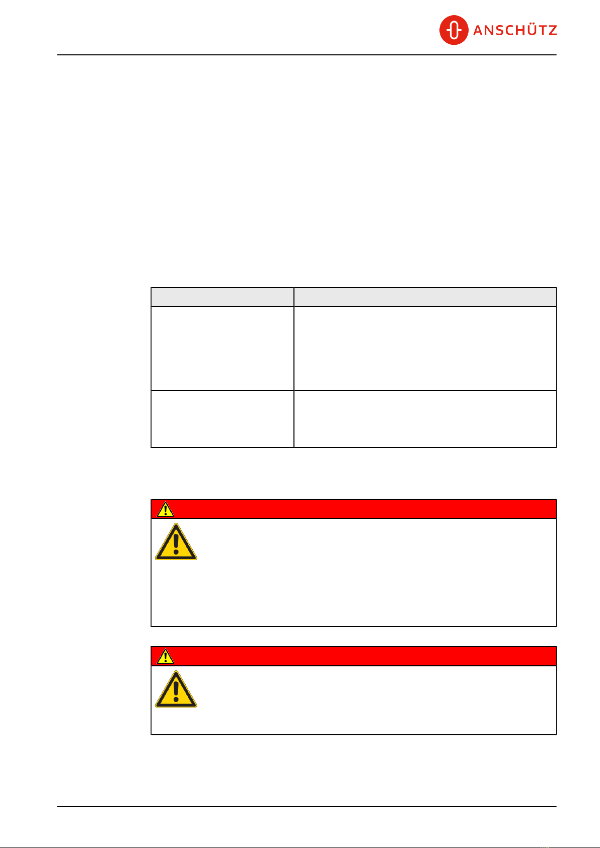
WARNING!
Danger due to maintenance and service by unskilled personnel
Risk of serious injury and material damage
• Keep all unskilled personnel away from the working area.
• Perform all maintenance and service only by skilled personnel.
WARNING!
Danger due to electrical current
Risk of death or serious injury that is caused by electrical shock
• Switch off voltage supply before starting work.
• Secure against switching on again.
• Perform work on the electric system only by skilled electricians.
CAUTION!
Hazard due to wrong disposal of harmful substances
Risk of environmental damage that is caused by wrong disposal
• Observe all national and regional disposal rules and regulations.
• Observe all disposal instructions that are placed on the components or
described in related documentation.
3.2 General Information
3.2.1 Reference to ISPC
All maintenance tasks comprise information about the support equipment, consumables
and spare parts that are used in this task.
Besides the designation and the quantity, a reference to the Illustrated Spare Parts
Catalog (ISPC) is given. The format of the reference is as follows:
aa-aaaa bb
Value Description
aa-aaaa Reference to the illustration in the ISPC
bb Position number on the illustration in the ISPC
Table of contents
Popular Media Converter manuals by other brands


Viking
Viking GLS-12 Technical practice

Benchmark
Benchmark DAC3 HGC Firmware Upgrade Instruction

Kramer
Kramer KDS-SW3-EN7 quick start guide

LANCAST
LANCAST twister 2111-12-01 Installation & user guide

Delta Electronics
Delta Electronics PMT Series instruction manual

Danfoss
Danfoss VLT 5000 Series operating instructions

Benchmark
Benchmark DAC1 USB instruction manual

Coopers of Stortford
Coopers of Stortford Skyline Music System Instructions for use

WEISS
WEISS DAC204 operating manual

Absolute Process Instruments
Absolute Process Instruments DuoPak APD 2003 manual

Digitus
Digitus DS-41200 user manual

Azbil
Azbil KUX60G user manual