manuals.online logo
Brands
  1. Home
  2. •
  3. Brands
  4. •
  5. ANTAIRA
  6. •
  7. Network Hardware
  8. •
  9. ANTAIRA LMP-1002G-10G-SFP User manual

ANTAIRA LMP-1002G-10G-SFP User manual

Antaira Technologies
LMP-1002G-10G-SFP
10-Port Industrial PoE+ Light Layer 3 Gigabit Managed Ethernet
Switch, w/8*10/100/1000Tx (30W/Port) + 2*1G/10G SFP+ Slots
Quick Installation Guide
Version 1.0
(February 2020)
Tel: 1-844-268-2472
Fax: 1-714-671-9944
www.antaira.com
19020000000096
Package Check List
The package contains the following items:
⚫1 –Quick installation guide
⚫1 –LMP-1002G-10G-SFP
⚫1 –Wall mounting bracket set with screws
⚫1 –DC cable –18 AWG & DC jack 5.5 x 2.1mm
⚫1 –RJ45 dust cover set
⚫1 –RJ45 to DB9 serial console cable
Front Panel Layout
Top Panel View
LMP-1002G-10G-SFP top panel is equipped with a 6-pin
removal terminal block connector (48~55VDC).
Product Overview
System Interface/Performance
All RJ45 ports support the auto MDI/MDI-X function
Embedded 8*10/100/1000Tx RJ45 ports (30W/Port) and
2*1G/10G SFP+ slots
Store-and-forward switching architecture
16K MAC address table
Power line EFT Protection: 2,000VDC; Ethernet ESD
Protection: 6,000VDC
Power Input & Connection
DC 48 to 55V redundant power, with a 6-Pin Removal
Terminal Block
It is recommended to use a UL listed industrial power supply
Operating Temperature
Standard operating temperature model: -40°C to 60°C
Case/Installation
IP30 protection
DIN-Rail and wall mount design
LED Indicators
LED
Color
Description
Power 1
Green
On
Power input 1 is active
Off
Power input 1 is inactive
Power 2
Green
On
Power input 2 is active
Off
Power input 2 is inactive
Status
Green
On
The system ready and work fine, and there are no
events occur
Red
On
System booting or an applied alarm (such as port
disconnect) has been triggered
Master
Green
On
ERPS Owner Mode (Ring Master) is ready
Off
ERPS Owner Mode is not active
Ring
Green
On
Ring Network is active
Off
Ring Network is not active
LAN Port 1~8
(Upper LED)
Green
On
Connected to network, 10/100/1000Mbps
Flashing
Networking is active
Off
Not connected to network
LAN Port 1~8
(Lower LED)
Green
On
The port is supplying power to the powered-device
Off
No powered-device attached or power supplying fails
LINK/ACT
(SFP Port 9~10)
Green
On
Connected to network, 10Gbps
Flashing
Networking is active
Off
Not connected to network
Amber
On
Connected to network, 1Gbps
Flashing
Networking is active
Off
Not connected to network
Grounding Screw
6-Pin Removal Terminal Block
LAN# 1~8 –10/100/1000Tx RJ45
LAN# 1~8 LED for PoE Status
LAN# 1~8 LED for Link/Activity Status
10/100/1000Mbps
LED for Power 1, Power 2, Status,
Master, and Ring
Grounding Screw
SFP Port# 9~10 LED for Link/Activity Status
1G/10G
Console Port
USB Configuration Backup
Reset Button
SFP Port# 9~10 –1G/10G
6-Pin Removal Terminal Block
Quick Installation
Ethernet Ports
RJ45 Ports (Auto MDI/MDI-X)
All RJ45 ports are auto-sensing for 10Base-T, 100Base-TX or
1000Base-T device connections. Please follow the wiring pin
assignment table below for Ethernet port installation.
RJ45 Ethernet Port Pin Outs
Pins
T568A Color
T568B Color
10Base-T,
100Base-TX
1000
Base-T(X)
Pin 1
white/green stripe
white/orange stripe
Rx+
TP0+
Pin 2
green solid
orange solid
Rx-
TP0-
Pin 3
white/orange stripe
white/green stripe
Tx+
TP1+
Pin 4
blue solid
blue solid
unused
TP2+
Pin 5
white/blue stripe
white/blue stripe
unused
TP2-
Pin 6
orange solid
green solid
Tx-
TP1-
Pin 7
white/brown stripe
white/brown stripe
unused
TP3+
Pin 8
brown solid
brown solid
unused
TP3-
Power Input Wiring
Please follow the steps below to insert the power wire:
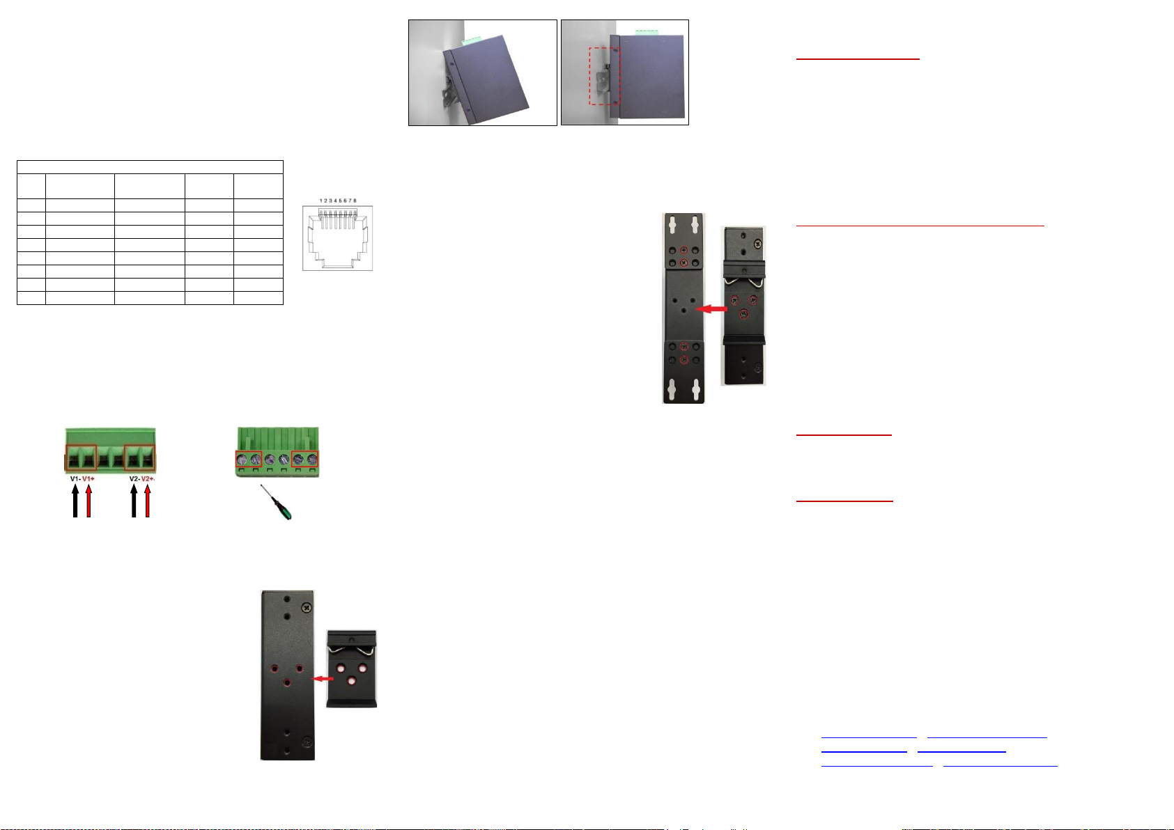
1. Insert the positive and negative wires into the PWR1
(V1+, V1-) and PWR2 (V2+, V2-) contacts on the
terminal block connector as shown below in Figure 1.
2. Tighten the wire-clamp screws to prevent the wires from
loosening, as shown below in Figure 2.
Figure 1 Figure 2
Industrial Switch Mounting
DIN-Rail Mounting
The DIN-Rail bracket is pre-installed on
the industrial Ethernet switch from the
factory. Please refer to Figure 3 for a
DIN-Rail bracket installation reference.
Follow the steps below for installing the
industrial switch on the DIN-Rail track:
1. Insert the top of the DIN-Rail on to
the track as shown below in Figure 4.
2. Lightly pull down the bracket on to
the rail as shown below in Figure 5.
3. Check if the bracket is mounted
tightly on the rail.
4. To remove the industrial
Ethernet
switch
from the rail, do the opposite from the steps above.
Wall Mounting
Follow the steps below to mount the industrial Ethernet switch
using the wall mounting bracket as shown below in Figure 6.
1. Remove the DIN-Rail bracket from the
industrial Ethernet switch by loosening
the screws.
2. Place the wall mounting brackets on
the top and bottom of the industrial
Ethernet switch.
3. Use the screws to screw the wall
mounting bracket on the industrial
Ethernet switch.
4. Use the hook holes at the corners of
the wall mounting bracket to hang the
industrial Ethernet switch on the wall.
5. To remove the wall mount bracket, do
the opposite from the steps above.
Field Maintenance and Service
⚫If the device requires servicing of any kind, the user is
required to disconnect and remove it from its mounting. The
initial installation should be done in a way that makes this as
convenient as possible.
⚫Voltage/power lines should be properly insulated as well as
other cables. Be careful when handling them so as to not trip
over.
⚫Do not under any circumstance insert foreign objects of any
kind into the heat dissipation holes located in the different
faces of the device. This may not only harm the internal
layout, but might cause harm to user as well.
⚫Do not under any circumstance open the device for any
reason. Please contact your dealer for any repair needed or
follow the instructions within the manual.
Warranty Policy
Warranty Conditions
Products supplied by Antaira Technologies are covered in this
warranty for sub-standard performance or defective
workmanship. The warranty is not, however, extended to goods
damaged in the following circumstances:
(a) Excessive forces or impacts
(b) War or an Act of God: wind storm, fire, flood, electric shock,
earthquake
(c) Use of unqualified power supply, connectors, or
unauthorized parts/kits
(d) Replacement with unauthorized parts
RMA and Shipping Costs Reimbursement
Customers shall always obtain an authorized "RMA" number
from Antaira before shipping the goods for repair or
replacement.
•Within the warranty period (based on the invoice date), all
parts and labor are free of charge to the customers.
•Customers are responsible for the cost of parts and labor, if
the products are out of warranty.
•For RMA service, customers are responsible for the shipping
expense for shipping the RMA unit(s) to Antaira. Antaira is
responsible for the shipping expense via a ground service
for the return repair/replace unit(s) back to customers.
Limited Liability
Antaira would not be held responsible for any consequential
losses from using Antaira’s product.
Warranty Period
5-Year Warranty
Antaira’s Customer Service and Support
•Antaira’s Technical Service & Support Centers:
+ 844-268-2472 (Antaira US Headquarter)
+ 48-22-862-88-81 (Antaira Europe Office)
+ 886-2-2218-9733 (Antaira Asia Office)
•Antaira’s Web Sites & Repair/Support Emails:
www.antaira.com / [email protected]
www.antaira.eu / [email protected]
www.antaira.com.tw / [email protected]
*Any changes will be announced on the Antaira website.
Figure 3
Figure 6
Figure 5
Figure 4

Other ANTAIRA Network Hardware manuals

ANTAIRA INJ-C201G-bt-100-24-T User manual

ANTAIRA

ANTAIRA INJ-C201G-bt-100-24-T User manual

ANTAIRA AMY-5133-AC-PD User manual

ANTAIRA

ANTAIRA AMY-5133-AC-PD User manual

Popular Network Hardware manuals by other brands

ADTRAN Total Access 374 Installation and maintenance guide

ADTRAN

ADTRAN Total Access 374 Installation and maintenance guide

Crestron QM-WMIC Operation and installation guide

Crestron

Crestron QM-WMIC Operation and installation guide

Tenda N3L-4H user guide

Tenda

Tenda N3L-4H user guide

MicroNet SP5736P user manual

MicroNet

MicroNet SP5736P user manual

Waveshare UART-WIFI232-B2 user manual

Waveshare

Waveshare UART-WIFI232-B2 user manual

evertz 7700 Series manual

evertz

evertz 7700 Series manual

Panasonic WJPB65M16 - VIDEO OUTPUT BOARD-WJSX650... operating instructions

Panasonic

Panasonic WJPB65M16 - VIDEO OUTPUT BOARD-WJSX650... operating instructions

Mazi INVR-16A user manual

Mazi

Mazi INVR-16A user manual

Western Digital My Cloud EX2 Ultra user manual

Western Digital

Western Digital My Cloud EX2 Ultra user manual

RTP 3000/06 Technical manual

RTP

RTP 3000/06 Technical manual

RTP 3159 Technical manual

RTP

RTP 3159 Technical manual

Saluki S3601 Series user manual

Saluki

Saluki S3601 Series user manual

HP E8491B IEEE 1394 Configuration and user's guide

HP

HP E8491B IEEE 1394 Configuration and user's guide

eks x-light manual

eks

eks x-light manual

TP-Link TL-CPE710 installation guide

TP-Link

TP-Link TL-CPE710 installation guide

Fortinet 3000B quick start guide

Fortinet

Fortinet 3000B quick start guide

Valcom VIP-814 installation manual

Valcom

Valcom VIP-814 installation manual

H3C SecPath L5030 installation guide

H3C

H3C SecPath L5030 installation guide

manuals.online logo
manuals.online logoBrands
  • About & Mission
  • Contact us
  • Privacy Policy
  • Terms and Conditions

Copyright 2025 Manuals.Online. All Rights Reserved.