manuals.online logo
Brands
  1. Home
  2. •
  3. Brands
  4. •
  5. ANTAIRA
  6. •
  7. PCI Card
  8. •
  9. ANTAIRA MSC-204A1-S User manual

ANTAIRA MSC-204A1-S User manual

Antaira Technologies
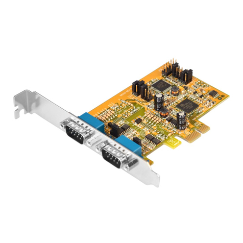
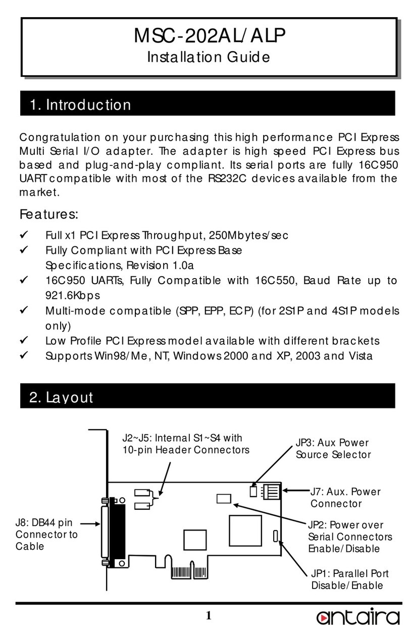
MSC-204A1-S
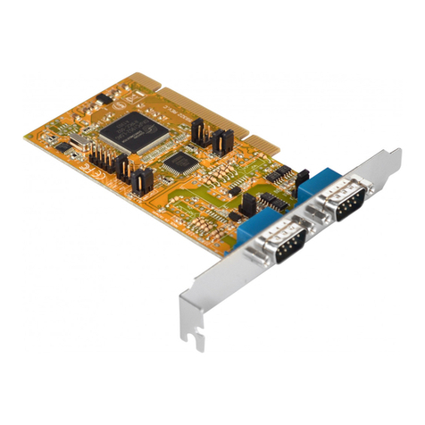
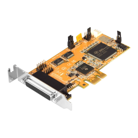
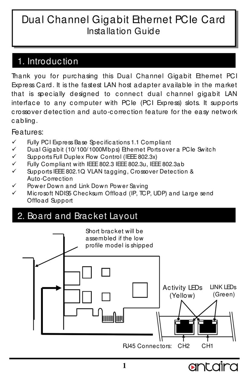
RS-232 PCI Express Serial Card Expansion with Octopus Cable
Quick Installation Guide
Version 1.0
(June 2017)
Tel: 1-844-268-2472
Fax: 1-714-671-9944
www.antaira.com
Package Check List
The package contains the following items:
1- Quick Installation Guide
1- MSC-204A1-S
Layout
Product Overview
System Interface/Performance
•Full x1 PCI Express throughput, 250Mbytes/sec
•Fully compliant with PCI Express Base Specifications,
Revision 1.1
•Supports low profile form factor with short bracket
•4 fully 16C1550 256-byte-FIFIO high performance
UARTs
•±15kV IEC1000-4-2 ESD Protection for RS-232 I/O's
•Baud rate up to 921.6 Kbps in an asynchronous mode
•256-byte deep FIFO per transmitter and receiver
•Supports 5V or 12V over pin-9 of DB9 connectors
•Software/Hardware Flow Control & Xoff Re-Transmit
•Supports Win98/ME, 2K, 2003, XP, Vista, Win 7, 8.x,
10, Linux, and Mac OS
Operating Temperature
Standard operating temperature model: 0°C ~ 55°C
Installation
PCIe Slot
Jumper Settings
JP2- External Power Enabler: There are 4 jumpers that
control the pin-9 signal of the 4 serial ports connectors
(S1~S4) respectively. If the jumper(s) is at the “DIS” position
(factory default), the pin-9 was connected with the RI signal
as standard RS232 definition. If the jumper is at the “PWR”
position, the pin-9 was connected with a power either from
PCI Express slot or from Aux Power connector (J7). The
power source is controlled by JP4 jumper (see the following
section).
JP3- External Power Selector: The pin-9 of the serial port
connector will be supplied with DC5V or DC12V. There are 3
sources depending on the jumper’s position of the JP4:
•AUX5V: DC5V, from J7, an optional power cable is
required.
•AUX15V: DC12V, from J7, an optional power cable is
required.
•PCI12V (factory default): DC12V, from PCI Express
golden finger, no cable is required.
Hardware Installation
1. Turn the system power OFF before installation.
2. Use static electricity discharge precautions.
3. Remove the chassis cover from your computer
4. Locate an unused PCI Express slot (typically white and
small) and remove the corresponding slot cover from
computer chassis.
5. Plug the I/O card to the unused PCI Express expansion
slot and attach the I/O card bracket to the computer chassis
screw.
6. Put the chassis cover back on the computer.
7. Turn ON the power of your computer and peripherals.
8. Proceed with Software Driver Installation.
Software Installation
PLEASE DO NOT LET WINDOWS AUTO SEARCH THE
DRIVERS ON THE CD. It will cause problems, because the
INF files will conflict in this case. Instead, please browse for
the correct location (folder) manually to make sure the
correct drivers are chosen and installed correctly.
Drivers are in each
corresponding folder
Note: Windows NT driver Installations
To install the Windows NT driver, please go into WinNT4
sub-directory and run (double click) Install_Serial.exe to
install all Serial Port Drivers.
Installing Windows Drivers:
1. When the system is powered, Windows will invoke
Windows’ New Hardware Wizard. Click “Next” to
continue. Select “Install from a list or specific
location (Advanced)”and click “Next “.
2. Select “Include this location in the search” then click
“Browse”to specify the driver’s location for your
Windows (for example,XP is E:\IO\OXFORD\XP32)
and click “Next” to continue.
3. Click “Next” to continue, and click “Finish” to
complete the installation.
4. To check the Installation, right click on “My
Computer”and choose “Manage”.Choose
“Device Manager”and double click “Ports”.
Software Installation
DB9(Male) on the 9-pin Flat Cable:
Note *: The pin-9 of the DB9 connector will output DC power if
the corresponding jumper was enabled.
10-pin Header Connectors S1~S4 (J4,J6,J5,J7):
Note *: The pin-9 of the DB9 connector will output DC power if
the corresponding jumper was enabled.
Maintenance and Service Field
If the device requires servicing of any kind, the user is
required to disconnect and remove it from its mounting. The
initial installation should be done in a way that makes this as
convenient as possible.
Please contact your dealer for any repair needed or follow
the instructions within the manual.
Warranty Policy
Warranty Conditions
Products supplied by Antaira Technologies are covered in this
warranty for sub-standard performance or defective
workmanship. The warranty is not, however, extended to goods
damaged in the following circumstances:
(a) Excessive forces or impacts
(b) War or an Act of God: wind storm, fire, flood, electric shock,
earthquake
(c) Use of unqualified power supply, connectors, or
unauthorized parts/kits
(d) Replacement with unauthorized parts
RMA and Shipping Costs Reimbursement
Customers shall always obtain an authorized "RMA" number
from Antaira before shipping the goods for repair or
replacement.
•Within the warranty period (based on the invoice date), all
parts and labor are free of charge to the customers.
•Customers are required to be responsible for the cost of
parts and labor, if the products are out of warranty.
•For RMA service, customers are required to be responsible
for the shipping expense for shipping the RMA unit(s) to
Antaira; and Antaira will be responsible for the shipping
expense by ground service for the return repair/replace
unit(s) back to customers.
Limited Liability
Antaira would not be held responsible for any consequential
losses from using Antaira’s product.
Warranty Period
5-Year Warranty
Antaira’s Customer Service and Support
•Antaira’s Technical Service & Support Centers:
+ 844-268-2472 (Antaira US Headquarter)
+ 48-22-862-88-81 (Antaira Europe Office)
+ 886-2-2218-9733 (Antaira Asia Office)
•Antaira’s Web Sites & Repair/Support Emails:
www.antaira.com / [email protected]
www.antaira.eu / i[email protected]
www.antaira.com.tw / i[email protected]
*Any changes will be announced on the Antaira website.
Pin#
Signal
Pin#
Signal
1
DCD
6
DSR
2
RXD
7
RTS
3
TXD
8
CTS
4
DTR
9
RI (*)
5
GND
Pin#
Signal
Pin#
Signal
1
DCD
6
DSR
2
RXD
7
RTS
3
TXD
8
CTS
4
DTR
9
RI (*)
5
GND
10
NC
2
1
10
9

Other ANTAIRA PCI Card manuals

ANTAIRA msc-116a User manual

ANTAIRA

ANTAIRA msc-116a User manual

ANTAIRA MSC-202B1 User manual

ANTAIRA

ANTAIRA MSC-202B1 User manual

ANTAIRA RS232 User manual

ANTAIRA

ANTAIRA RS232 User manual

ANTAIRA MSC-204A2 User manual

ANTAIRA

ANTAIRA MSC-204A2 User manual

ANTAIRA MSC-102B1L User manual

ANTAIRA

ANTAIRA MSC-102B1L User manual

ANTAIRA Dual Channel Gigabit Ethernet PCIe Card User manual

ANTAIRA

ANTAIRA Dual Channel Gigabit Ethernet PCIe Card User manual

ANTAIRA MSC-202ALP User manual

ANTAIRA

ANTAIRA MSC-202ALP User manual

ANTAIRA MSC-102B1 User manual

ANTAIRA

ANTAIRA MSC-102B1 User manual

ANTAIRA RS232 User manual

ANTAIRA

ANTAIRA RS232 User manual

ANTAIRA SC-102AL-1 User manual

ANTAIRA

ANTAIRA SC-102AL-1 User manual

ANTAIRA msc-401a1 User manual

ANTAIRA

ANTAIRA msc-401a1 User manual

ANTAIRA MSC-104B User manual

ANTAIRA

ANTAIRA MSC-104B User manual

ANTAIRA MSC-202A-V2 User manual

ANTAIRA

ANTAIRA MSC-202A-V2 User manual

ANTAIRA msc-216a User manual

ANTAIRA

ANTAIRA msc-216a User manual

ANTAIRA RS232 User manual

ANTAIRA

ANTAIRA RS232 User manual

ANTAIRA MSC-204B1 User manual

ANTAIRA

ANTAIRA MSC-204B1 User manual

ANTAIRA MSC-202AL User manual

ANTAIRA

ANTAIRA MSC-202AL User manual

ANTAIRA MSC-208A User manual

ANTAIRA

ANTAIRA MSC-208A User manual

ANTAIRA MSC-102B1-SI User manual

ANTAIRA

ANTAIRA MSC-102B1-SI User manual

Popular PCI Card manuals by other brands

Rosewill RC-301EU user manual

Rosewill

Rosewill RC-301EU user manual

IBM Gigabit Ethernet-SX PCI Adapter Installation and user guide

IBM

IBM Gigabit Ethernet-SX PCI Adapter Installation and user guide

D-Link WDA-2320 RangeBooster G Quick installation guide

D-Link

D-Link WDA-2320 RangeBooster G Quick installation guide

ADLINK Technology PCIe-GIE7 Series manual

ADLINK Technology

ADLINK Technology PCIe-GIE7 Series manual

Advantech PCI-1751 user manual

Advantech

Advantech PCI-1751 user manual

Avermedia AVerDVD EZMaker Quick installation guide

Avermedia

Avermedia AVerDVD EZMaker Quick installation guide

TRENDnet TEG-PCITXRL Specifications

TRENDnet

TRENDnet TEG-PCITXRL Specifications

Datapath VisionLC-SDI manual

Datapath

Datapath VisionLC-SDI manual

AmbiCom WL54-PCIe Specifications

AmbiCom

AmbiCom WL54-PCIe Specifications

StarTech.com PEX2S1P553B instruction manual

StarTech.com

StarTech.com PEX2S1P553B instruction manual

Beckhoff FC7501 Documentation

Beckhoff

Beckhoff FC7501 Documentation

Digitus DS-30220-4 user manual

Digitus

Digitus DS-30220-4 user manual

Nokia C910 user guide

Nokia

Nokia C910 user guide

OpenVox B200P user manual

OpenVox

OpenVox B200P user manual

AT&T Plug&Share 6550G quick start guide

AT&T

AT&T Plug&Share 6550G quick start guide

ICP DAS USA PCI-1002 Series user manual

ICP DAS USA

ICP DAS USA PCI-1002 Series user manual

Avago LSI SAS 9311-8i user guide

Avago

Avago LSI SAS 9311-8i user guide

StarTech.com PCIE1RIS instruction manual

StarTech.com

StarTech.com PCIE1RIS instruction manual

manuals.online logo
manuals.online logoBrands
  • About & Mission
  • Contact us
  • Privacy Policy
  • Terms and Conditions

Copyright 2025 Manuals.Online. All Rights Reserved.