Antaisola Rail IV User manual

Always be your solar support
Installation Manual—Rail IV
Pitched Roof Solution
Version 2016 1.0
www.antaisolar.com

Pitched roof mount installation manual –Version 2016 1.0 to AS/NZS1170.2.2011 Amdt 3 –2012 1
GENERAL INTRODUCTION
Antaisolar Roof Mounted solutions, accommodating a wide range of modules, are suitable for most
types of roofs. With innovative Antaisolar Rail and T module, Antaisolar Roof Mount enables
significantly faster, easier installations, which have been developed into one of the most versatile
mounting solutions in the world, delivering time and cost effective experience to solar system
installers.
Rail IV
Easy to be installed
Antaisolar features series of highly engineered new innovative product, designed with experienced
engineers to the speed of installation.
Antaisolar pitched roof solar mounting system is backed by a 10-year warranty and is compliant with
AS/NZS1170.2.2011 Amdt 3 –2012
Benefits of Antaisolar Pitched Roof Mounting System
● Easy Installation
● Diversified Application
● High Accuracy
● Choice Quality
● Engineered to highest standards
● Maximum Lifespan
● Guaranteed durability
TECHNICAL SPECIFICATIONS

Pitched roof mount installation manual –Version 2016 1.0 to AS/NZS1170.2.2011 Amdt 3 –2012 2
Applications
Commercial and residential buildings
Marine applications and remote areas
Features
Anodized 6005-T5 aluminum extrusion
Innovated designed of the Tilt-in modules, which can be pre-assembly with the clamp, make the
installation easy and quick.
Suitable for difference conditions and the most solar panels at present market.
Significantly higher strength-to-weight ratio than other framing products, providing improved
efficiency due to greater frame spans, inherent corrosion resistance resulting in low ongoing
maintenance and an extended product life.
Complies with Australian/New Zealand Standard on Wind Actions, AS/NZS1170.2.2011 Amdt 3 –
2012
10 years limited warranty backed up by parent company Antai Aluminium
Material
Material
Tensile strength
Ultimate
Yield
6005 T5 aluminum
extruded
260Mpa
240Mpa
Stainless steel 304
625.55Mpa
263.8Mpa
Stainless steel A2-70
700MPa
450Mpa
Installation condition
Roof slope
Up to 60°
Building height
Up to 20m
Mounting structure
Timber/ steel
Roof types
Tile/Tin/Klip-Lok® roof
System angle
Flush with roof
Note: If the condition is beyond the table list, please contact us to confirm

Pitched roof mount installation manual –Version 2016 1.0 to AS/NZS1170.2.2011 Amdt 3 –2012 3
SAFETY AND INSTALLER RESPONSIBILITIES
Handling and Installing Antaisolar
It is critically important that safety practices are observed when installing
Do not throw or roughly handle any Antaisolar components.
Do not bring Antaisolar system into contact with sharp or heavy objects.
Do not modify Antaisolar components in any way. The exchange of bolts, drilling of holes, bending or any
other physical changes not described in standard installation procedure will void the warranty.
It is the installer’s responsibility to verify the integrity of the structure to which Antaisolar components is
fixed. Roofs or structures with rotten/rusted bearers, undersized bearers, excessively spaced bearers, or
any other unsuitable substructure cannot be used with Antaisolar components, and installation on such
structures will void the warranty, and could result in death or serious injury.
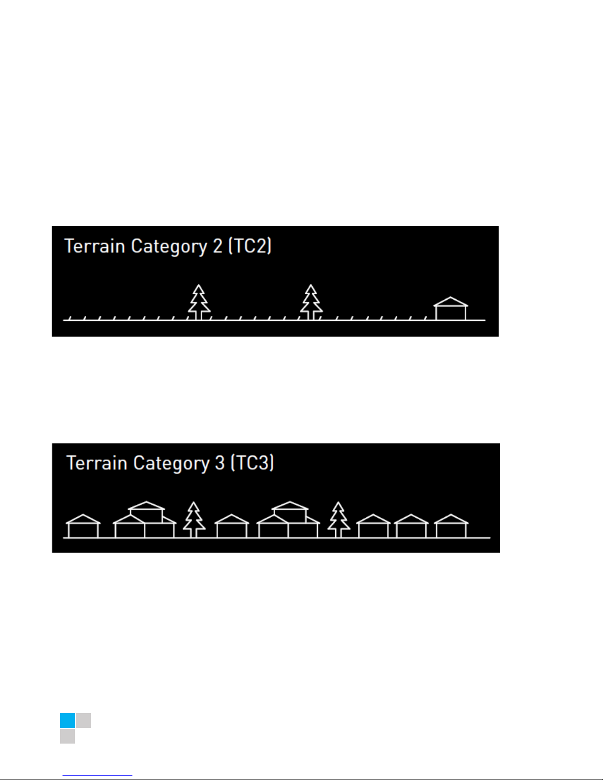
Wind and Climate Design
AS/NZS1170.2.2011 provides guidance on determining the wind pressures applicable to your Antaisolar
system install site, taking into account roof shape and geographic location. Sufficient guidance is given in this
document, but you may wish to procure a copy of these standards if your company installs Australia/New
Zealand wide.
REMEMBER average wind speeds are higher for structures mounted closer to the roof perimeter zone
(edge). Refer to ‘Fixing within Roof Installation Zone’ for more information)
Make sure your installation complies with local and national building codes. Take into account relevant
design parameters (wind speed, exposure and topographic factor) when determining the loading for the
installation.
If alternative fasteners are used to ix the framing to the roof (assuming supplied fasteners are unsuitable
for any reason), all screw fasteners must conform to corrosion resistance Class 4 Australian Standard
AS3566 and be of equal or greater strength to those supplied with your Antaisolar system order.
CAUTION: INSTALLATION OF THIS PRODUCT IS TO BE PERFORMED ONLY BY PROFESSIONALLY TRAINED
INSTALLERS. ANY ATTEMPT BY AN UNQUALIFIED PERSON TO INSTALL THIS PRODUCT COULD RESULT IN
DEATH OR SERIOUS INJURY.

Pitched roof mount installation manual –Version 2016 1.0 to AS/NZS1170.2.2011 Amdt 3 –2012 4
COMPONENTS LIST
Overview of system components
Part name
Picture
Part name
Picture
Rail IV
Rail splice for rail IV
T-module
L Bracket
(L Foot)
Inter Clamp
(with T-module)
End Clamp
(with T-module)
Tile Roof hook
Hexagon socket
bolt
M8*30/45/50/55/60
Klamp Lock 700
Klamp Lock 406
Note: The quantity of requested components depends on the system you ordered.

Pitched roof mount installation manual –Version 2016 1.0 to AS/NZS1170.2.2011 Amdt 3 –2012 5
BEFORE INSTALLING
Receipt of goods
Check that the Antaisolar equipment is undamaged and that the order is complete. Check for correct
quantities of the items.
Tools required for installation
6 mm Allen key or hexagonal driver bit.
If using a 6mm driver bit, make sure the cordless
power tool used for the driving has a hand-tight
clutch setting a fine (soft) impact drive to prevent
damage to the fragile glass panels and threads on the
structure.
Cordless drill.
Drill or impact driver for driving roof material
fixings
Angle grinder.
For terracotta tile roof installation, and angle
grinder fitted with a continuous edge diamond
tipped tile cutting blade; gloves, hearing
protection, a face protection mask, and a suitably
rated breathing protection mask for all people in
proximity of grinding
Gloves.
Protect the hazard of the sharp corners.
Cord or color pen.
Mark the installation position.
Spirit level
Measuring tape

Pitched roof mount installation manual –Version 2016 1.0 to AS/NZS1170.2.2011 Amdt 3 –2012 6
*If necessary, timber to shim the roof hook
INSTALLATION PLANNING
DETERMINING WIND TERRAIN CATEGORY
Terrain Category 2
Open terrain, including grassland with well scattered obstructions having heights generally from
1.5 meters to 5 meters. Examples include farmland or cleared sub-divisions with isolated trees and
uncut grass.
Terrain Category 3
Terrain with numerous closely spaced obstructions having heights generally from 3 meters to 10
meters. Examples include typical suburban housing or light industrial areas.

Pitched roof mount installation manual –Version 2016 1.0 to AS/NZS1170.2.2011 Amdt 3 –2012 7
DETERMINING WIND REGION
Figure: National wind map (in accordance with AS/NZS 1170.2:2011/Amdt 3:2012)
Wind regions are pre-defined by Standard AS/NZS 1170. The Wind Region has nothing to do with
surrounding topography or buildings.
Wind Zone
A
B
C
D
Wind Speed (m/s)
41
48
69
88
PLANNING THE MODULE AREA
Solar panels can be installed anywhere on the roof, as long as sufficient fixings are used. Higher wind speeds
are encountered at the edges of roofs and therefore more fixings are required in these areas. For a flush
mounted array, a roof can be divided into two zones, the central zone and the end zone. The width of these
zones can be determined based on the length of the building.
Determining the width of the central and end zones, ‘B/3’. The width of the central and end zones is
determined by calculating the roof length and dividing this result by 3. An exclusion zone of 600 mm must be
made on the edges of the roof.

Pitched roof mount installation manual –Version 2016 1.0 to AS/NZS1170.2.2011 Amdt 3 –2012 8
Figure: Panel must be installed flat to the roof
DETERMINE THE HEIGHT OF THE INSTALLATION SITE
This document provides sufficient information for Antaisolar system installation height less than 20 meters.
If your installation site is more than 20 meters in height, please contact Antaisolar to obtain engineering data
to support your installation.
VERIFY ACCEPTABLE RAIL END OVERHANG
Rail end overhang must equal 50 percent or less of foot spacing. Thus, if foot spacing is 1200mm, the
Rail end over hang can be up to 600mm. In this case, two feet can support a rail of as much as 2400mm
(1200mm between the feet and 600mm of overhang at each end).
DETERMINE ROOF SLOPE
Antaisolar mounting system can be used for roof slope up to 60 degrees. This document provides sufficient
information for below 30 degrees, please contact Antaisolar for between 30 and 60 degrees.
DETERMINE THE MAXIMUM RAIL SUPPORT SPACING
Please use the table in certification of compliance to determine the Antaisolar Rail IV support spacing for
installations. Certification of compliance please request from dealer or contact Antaisolar. Below only for
reference.

Pitched roof mount installation manual –Version 2016 1.0 to AS/NZS1170.2.2011 Amdt 3 –2012 9
INSTALLATION INSTRUCTION
Installation of L-bracket on Metal Roof
1. Determine the positions of the
L-bracket according to your plans.

Pitched roof mount installation manual –Version 2016 1.0 to AS/NZS1170.2.2011 Amdt 3 –2012 10
2. Fix the L bracket (together with
Rubber Pad) to the rafter using SUS
410 Screw, fix other L brackets to the
rafter according to your plans.
Note: The rubber pad plays the role
of waterproof.
Installation of Klamp Lock on Metal Roof
3.Use our Klamp Lock to clip the
metal roof tightly, and place
L-Bracket on Klamp Lock and
connect them by tightening M8*20
Bolt.
Note: If Klamp Locks are being used
then fixing centres are subject to
those outlined installation manual for
Klamp Lock 406 & Klamp Lock 700.
4. Connect the L bracket with rail IV
by T-module and tighten the bolt.

Pitched roof mount installation manual –Version 2016 1.0 to AS/NZS1170.2.2011 Amdt 3 –2012 11
5. If you need, to connect multiple
rails together, slide the splices on the
rear side of the pre-assembled rails
halfway to the side. Fasten the first
M8 bolt firmly using the Allen key.
Now slide the next rail segment into
the splice. Tighten the second M8
bolt .The connection is finished.
Installation of Tile Hook on Tile Roof
6. Remove the roof tiles at the
marked positions or simply lift them
up slightly then input the roof hook
to the wooden beam. Fix the roof
hooks with 3x self-tapping screws.
Minimum 2 pcs
7. Cover the hooks by the removed
tile
8. Connect the roof hook with the
rail.
a. Insert the tilt-in module into the
side channel of the rail as the step 9
shown.
b. Adjust the rail to be level.
c. Fasten the bolt.

Pitched roof mount installation manual –Version 2016 1.0 to AS/NZS1170.2.2011 Amdt 3 –2012 12
Note: If necessary, use an angle
grinder or hammer to cut a concavity
in the tile that covers the roof hook
at the point where the roof hook
comes through. (Caution! Must not
use fixed roof hook as a ladder, as
this extreme point load could
damage the tile below.
9. Place the solar module on the
rails, slide the end clamp tightly
against the solar module and fasten
tightly using the Allen bolt
(recommended torque is 8 Nm)
10. Slide the pre-assembled
inter-module clamp into the rails
from above, place it firmly against
the module and fasten loosely
(approx. 2-3 turns).
11. Now slide the next module
against the previously installed
module and tighten the inter-module
clamp using the Allen key, Take care
that the anti-slips protection sits in
the rail channel of the lowest row of
rails.

Pitched roof mount installation manual –Version 2016 1.0 to AS/NZS1170.2.2011 Amdt 3 –2012 13
12. Place the last module in the row on the rails (with
the first row of modules, take care that the nti-slip
protection sits properly in the rail channel) and fasten
the last inter module clamp and the module end clamp
using the Allen Key (recommended torque is 8 Nm).
13. For each use of the T module. You must make sure
that: the thread of the screws does not project through
the lower side of the T module (max flush). Position
the T module in the rail channel and fasten it loosely
with2 to 3 turns of the screw. The screws can still be
freely moved in the rail channel. Slide the screw to
their final position in connection with the inter-module
clamp, module end clamp or roof hooks/hanger bolts
and fastens firmly.
14. Now first row of modules are installed, continue to
mounting next row of modules according to steps 7 to
10.
15.Antai rail grounding system

Pitched roof mount installation manual –Version 2016 1.0 to AS/NZS1170.2.2011 Amdt 3 –2012 14
WARRANTY
In so far as Xiamen Antai New Energy Tech. Co., Ltd. (Hereafter called Antaisolar) grants the customer a 10
year warranty to solar mounting systems, except for the anodized finish, which finish shall be free from
visible peeling, or cracking or chalking under normal atmospheric conditions for a period of five (5) years.
The Warranty Start Date is the date of delivery of the Product(s) to the Buyer or 2 months after the date of
Product(s) dispatch from Antaisolar manufacturing site, whichever date is earlier.
Warranted Products
All anodized aluminum products and stainless steel 304 components in the solar mounting systems.
Exclusions and Limitations
In the event that damage is caused to a purchased item, despite proper installation and handling and in the
context of normal use and maintenance, Antaisolar will immediately exchange the respective component
within the warranty period. The following terms shall apply
1. Failure to comply with Antaisolar’ s installation manual;
2. Service by service technicians who are not qualified under the relevant law and/or applicable regulations
at the place of installation;
3. The warranty period for each component defined in the respective product sheet by Antaisolar shall apply.
The warranty period commences with the transfer of risk of the respective component; if, for particular
components, generally or for a particular type of use a possible shorter life is expressly indicated within
Antaisolar’ s individually-generated plans, an exchange is scheduled within a shorter period, the warranty
period shall be restricted to such life or period.
4. The warranty is limited to additional delivery for the defective components upon notification of the
damage within the warranty period. Any statutory guarantee or liability claims shall remain unaffected.
5. The obligation to fulfill the warranty shall not apply if the damage has arisen in connection with
exceptional stress (e.g. storm damage, impact of instability of the sub-surface, particular chemical or
biological effects). Or in such conditions, accident, force of nature (such as lightning strike, earthquake),
influence from chemical products or other acts beyond Antaisolar’s reasonable control (including damage
by fire, flood, etc.)
6. With regard to installation and handling, the technical product descriptions and installation instructions
regarding the respective products as supplied by us shall apply, as shall the statutory and
generally-recognized standards and principles of building and construction work in local market as well as,
as appropriate, on a priority basis, the plans, statics and instructions prepared by us individually for the
customer.
7. No claims shall exist if the damage is covered or can usually be covered by insurance against storm and
similar events (natural-peril insurance).
8. This warranty shall only be applied to solar mounting systems designed by Antaisolar. Custom design
products if suggestions by Antaisolar are declined, this product is excluded in this warranty.
9. This warranty shall only establish claims of Antaisolar’s customer, via which all warranty claims are to be
settled. Assertion by third parties shall only be possible if Antaisolar agrees thereto.
10. Limited Warranty does not apply to any Products which have been subjected to use of the Products in
such a manner as to infringe Antaisolar’s or any third party`s intellectual property rights (e.g. patents,
trademarks).

Pitched roof mount installation manual –Version 2016 1.0 to AS/NZS1170.2.2011 Amdt 3 –2012 15
Repair, Replacement or Refund Remedy
1. As Buyer’s sole and exclusive remedy under this Limited Warranty (though Buyers should note paragraph
4 below regarding the potential existence of other statutory rights), Antaisolar will, in its sole discretion,
either, with regard to the applicable Product (or component thereof in the case of Mounting Product):
a) refund the historical purchase price of the relevant Product(s); or
b) repair the defective Product(s) at no charge (subject to the following paragraph); or
c) replace the defective Product(s) or part thereof by a new or remanufactured equivalent at no charge
(subject of the following paragraph).
In the event that Antaisolar opts for options b) or c), Antaisolar shall bear all insurance and transportation
charges (except air freight, courier freight), customs clearance and any other costs for returning the
defective Product(s) to Antaisolar and shipping the repaired or replaced Product(s) to Buyer (a Buyer may
claim reimbursement by Antaisolar for these charges by contacting Antaisolar and providing proof to
Antaisolar that these charges were incurred, e.g. an invoice from the relevant service provider). The costs
and expenses for their removal, installation or reinstallation shall remain with Buyer.
2. The warranty period(s) shall not extend or renew upon the repair or replacement of a defective Product by
Antaisolar. The warranty period for replaced or repaired Product(s) is the remainder of the warranty on the
original new Product(s).
3. All other claims under this Limited Warranty against Antaisolar shall be excluded. Under this Limited
Warranty, Antaisolar is not responsible for any special, incidental or consequential damages (including loss
of profits, harm to goodwill or business reputation, or delay damages) whether such claims are based in
contract, warranty, negligence or strict tort. This exclusion applies to the extent permissible by law, and even
if the remedies set forth below herein are deemed to have failed of their essential purpose.
Rights and Remedies against Third Parties
This Limited Warranty shall be construed as a separate warranty and independent from any other
contractual arrangement with third parties relating to the Product(s). It shall not affect any rights,
obligations and remedies of the Buyer, if any, with regard to third parties for defects or non-conformity or
non-compliance of the Products, notwithstanding its legal basis. The rights and remedies provided
hereunder are in addition to any other rights and remedies against third parties to which Buyer may be
entitled by agreements with such third parties or by law.
Claims Procedure, Notice Periods, Expiration of Warranty Claims and Limitations
1. Buyer shall notify Antaisolar immediately after discovery of any claim under this Limited Warranty by
letter, facsimile or e-mail specifying each alleged claim including evidence of the claims and the serial
numbers of the Product(s) at issue.
2. Any claim for breach of this Limited Warranty must be brought within three (1) months after discovery
of the breach.
3. The return of any defective Product(s) will not be accepted unless prior written authorization has been
given by Antaisolar.

Pitched roof mount installation manual –Version 2016 1.0 to AS/NZS1170.2.2011 Amdt 3 –2012 16
Force Majeure
Antaisolar shall not be responsible or liable in any way to the Buyer for any non-performance or delay in
performance under this Limited Warranty due to occurrences of force majeure such as, war, riots, strikes,
unavailability of suitable and sufficient labor, material, or capacity or technical or yield failures and any
unforeseen event beyond its control, including, without limitation, any technological or physical event or
condition which is not reasonably known or understood at the time of the sale of the defective Product(s) or
the notification of the relevant warranty claim under this Limited Warranty.
Warranty Assignment
This Limited Warranty is only applied when the Products remain installed in their original installation
location.
Validity
This Limited Warranty shall apply to Product(s) manufactured after 1st January 2014. This Limited Warranty
shall be valid until a new revision is issued by Antaisolar.
No other Warranty
Unless modified in a writing signed by an officer of Antaisolar, the Limited Warranty set forth herein is the
only express warranty (whether written or oral) by Antaisolar applicable to the Products and no one is
authorized to restrict, expand or otherwise modify this Limited Warranty.
Miscellaneous
If any provision of this Limited Warranty is held invalid, unenforceable or contrary to law then the validity of
the remaining provisions of this Limited Warranty shall remain in full force and effect.
MAINTENANCE AND CLEANING

Pitched roof mount installation manual –Version 2016 1.0 to AS/NZS1170.2.2011 Amdt 3 –2012 17
6005-T5 anodized aluminium is largely maintenance free. Only in highly polluted or marine conditions is
rinsing with clean water required, during scheduled panel cleaning.
REFERENCES
AS/NZS 1170.2:2011/Amdt 3:2012 on wind actions
AS/NZS16641.1:1997 on aluminium structures
AS1720.1:2012 on timber structures
AS/NZS4600:2005 on cold-formed steel structures
AS3566-2011, self-drilling screws for the building and construction industries.
CONTACT DETAILS:
Xiamen Antai New Energy Tech. Co., Ltd.
Address: Room 402, No.21 Wanghai Road, Software Park II Siming District, Xiamen,
China 361008
Tel: +86 592 5902557
Fax: +86 592 5508270
Email: info@antaisolar.com
APPENDIXES:
-Array Frame Engineering Certificate - Flush Mount (Tile Roof)
-Array Frame Engineering Certificate - Flush Mount (Tin Roof)
-Array Frame Engineering Certificate - Flush Mount with Kliplok Clamps
These Engineering Certificates contain important installation requirements. Please obtain these
certification from your distributor.
Table of contents
Popular Solar Panel manuals by other brands

Kyocera
Kyocera KK255P-3CB2CG Assembly and maintenance instructions

Grape Solar
Grape Solar CS-S-160-DJ Safety and installation manual

Epever
Epever LORA 433A manual

Mission Solar Energy
Mission Solar Energy PERC Series Installation and user manual

CSUN
CSUN 305-72M installation guide

Aqua Creek Products
Aqua Creek Products F-SLR manual

Qcells
Qcells Q.PEAK DUO L-G8.3 / BFG Q.PEAK DUO L-G8.3 /... Installation and operation manual

CanadianSolar
CanadianSolar CS5AH-180M installation manual

Qcells
Qcells Q.PEAK DUO XL-G11.2 Series Installation and operation manual

Num'axes
Num'axes NGPIEACC033 user guide

Aqua PRO
Aqua PRO AP300SP instructions

CORAB
CORAB PI-94M installation manual