A
E
D
C
B
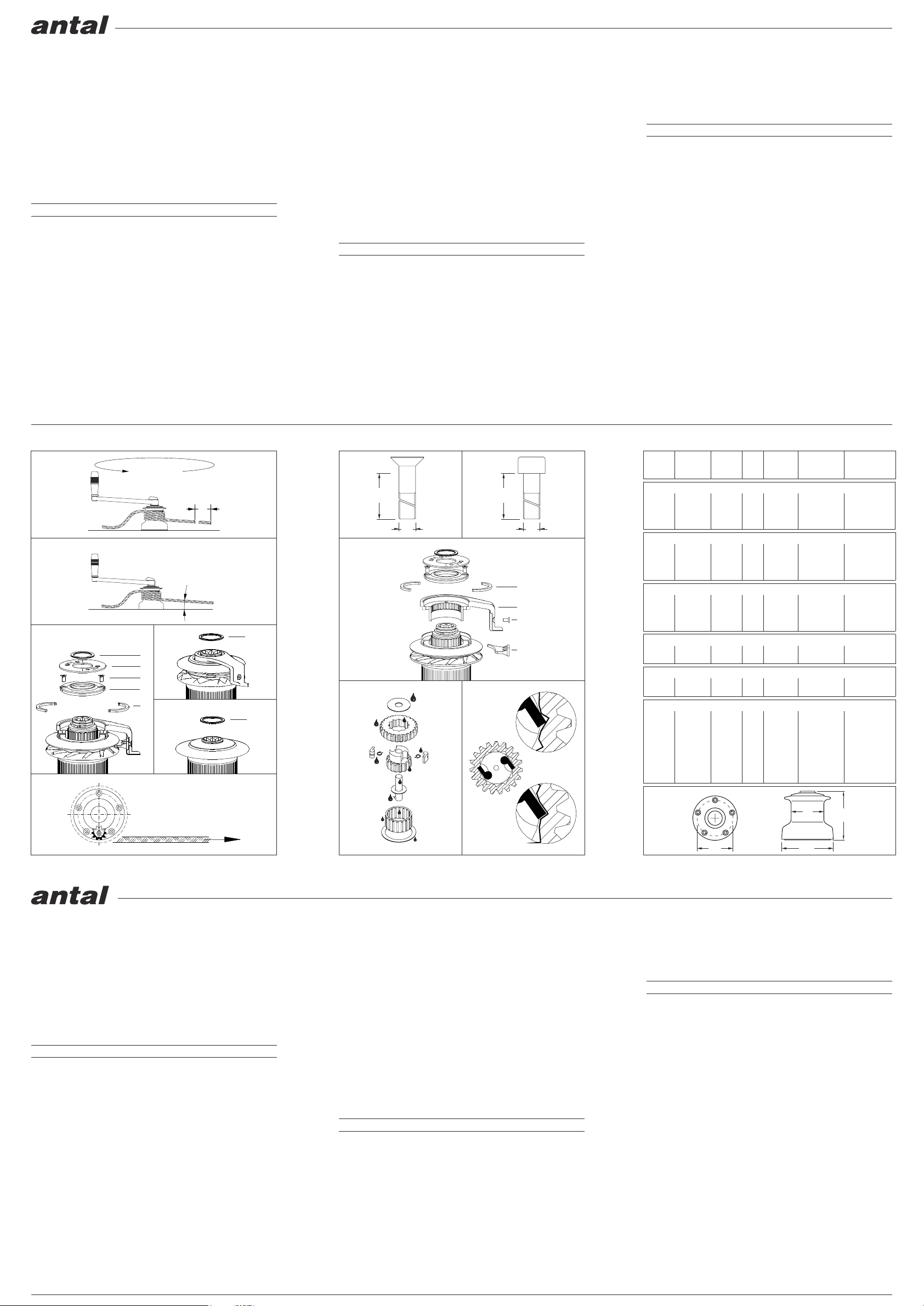
Fig. 3
P
S
1 giro
1 turn
Fig. 1
NO
SI’
Fig. 11
Fig. 8
2°-10°
Fig. 2
A
Fig. 4
A
Fig. 5
Fig. 6
F
G
H
E
Fig. 9
Fig. 7
Fig. 10
SELF TAILING - TWO SPEED (2 RED.) - DUE VELOCITA’ (2 RID.)
W40ST 40,0 12,8 40 125 8/14 4,6 6,2 151 80 168 5 x 8 118
W44ST 43,0 20,0 38 80 8/16 6,3 8,8 173 93 194 6 x 8 147
W48ST 46,3 24,6 35 65 8/16 7,8 10,5 182 93 205 6 x 8 156
W52ST 51,1 14,9 31 107 10/18 9,1 12,4 204 104 228 6 x 8 174
W60ST 61,2 18,7 26 85 10/18 11,0 14,4 224 105 234 6 x 10 190
W65ST 65,2 26,2 24 61 10/20 14,5 18,9 248 120 255 6 x 10 208
W66ST 65,6 18,0 24 89 12/22 16,5 22,2 248 144 271 6 x 10 208
W70ST 69,8 27,1 23 59 12/22 21,4 26,7 290 144 298 6 x 10 228
STANDARD - TWO SPEED (2 RED.) - DUE VELOCITA’ (2 RID.)
W44 43,0 20,0 38 81 5,5 8,5 173 93 177 6 x 8 147
W48 46,3 25,0 36 65 6,3 9,5 182 93 189 6 x 8 156
W52 51,1 14,9 31 107 7,8 11,5 204 104 194 6 x 8 174
W60 61,2 18,7 26 85 9,5 12,6 224 105 211 6 x 10 190
STANDARD - ONE SPEED (1 DIR.) - UNA VELOCITA’ (1 DIR.)
W6 6,7 188 0,4 94 60 87 5 x 6 66
W7 6,7 188 0,7 97 60 95 5 x 6 79
W8 7,3 220 1,5 2,1 110 70 105 5 x 6 83
W9 6,8 235 2,0 127 74 122 5 x 6 93
1° 2° 1° 2° Ø mm AL BR mm mm mm N°x mm Ø mm
SELF TAILING - ONE SPEED (1 RED.) - UNA VELOCITA’ (1 RID.)
W16ST 14,5 110 8/12 2,6 3,6 110 71 130 5 x 6 82
W30ST 28,0 60 8/12 3,0 4,3 128 75 147 5 x 6 92
SELF TAILING - TWO SPEED (1 DIR. + 1 RED.) - DUE VELOCITA’ (1 DIR. + 1 RID.)
W16.2ST 14,5 7,3 110 220 8/12 2,6 3,6 110 71 130 5 x 6 82
W30.2ST 28,0 6,8 60 235 8/12 3,0 4,3 128 75 147 5 x 6 92
POTENZA
I winches vengono normalmente identificati per il proprio
rapporto di potenza 1:P, cioè il rapporto fra la forza applicata sulla
manovella ed il tiro ottenibile trascurando gli attriti.
ITALIANO
MODELLI SELF-TAILING DAL W40 AL W70 (fig. 3)
Togliere il seger A, sollevare il disco inox B e quindi svitare le
viti C, togliere il coperchio in plastica D.
A questo punto è possibilie togliere i due semianelli grandi E
che permettono di sfilare la campana, completa dei dischi e del
braccio ST.
MODELLI SELF-TAILING W16 E W30 (Fig. 4)
E’ sufficiente togliere il seger A per poter sfilare la campana,
completa dei dischi e del braccio ST.
MODELLI NON SELF TAILING - TUTTI (Fig. 5)
E’ sufficiente togliere il seger A per poter sfilare la campana.
APERTURA DEL WINCH
Per avere accesso ai fori di fissaggio del winch è necessario
togliere la campana.
1.
ostruire i canali di drenaggio ricavati nella base.
Per tutti i modelli tranne W65-66-70 occorrono bulloni a testa
svasata (Fig. 7). Per i modelli W65-66-70 occorrono bulloni a
testa cilindrica (Fig. 8).
Il numero ed il diametro dei bulloni è riportato in tabella, mentre la
lunghezza dipende dallo spessore della coperta.
FISSAGGIO DELLA BASE
Prima di bloccare i bulloni di fissaggio, interporre del sigillante tra
winch e coperta per evitare infiltrazioni, facendo attenzione a non
3.
MONTAGGIO DEL WINCH
Procedere al rimontaggio della campana, operando in maniera in
versa allo smontaggio.
4.
SELF TAILING SU MOLLE
Questo sistema di ST autoregolante è utilizzato su tutti i modelli.
Il self-tailing su molle si regola automaticamente su un ampio
range di diametri di scotta.
E’ necessario non superare mai i diametri massimi previsti
per ogni modello che sono riportati nella tabella.
ORIENTAMENTO DEL BRACCIO ST (Fig. 9)
Dopo aver eseguito la procedura di apertura del winch ed aver
tolto i due semianelli grandi E, è necessario togliere la vite F
dell’espulsore G e quindi sfilare il solo braccetto ST (H); questo
ultimo può essere posizionato con diversi orientamenti, in base a
dove si vuole raccogliere la manovra.
5.
POSIZIONAMENTO DELLA BASE
Posizionare il winch in modo che l’ingranaggio che trasmette il
moto alla campana sia tangente rispetto alla direzione del tiro
(vedi fig. 6), quindi segnare la posizione dei fori di fissaggio,
spostare il winch e procedere alla foratura.
2.
POSIZIONE DEL VERRICELLO (Fig. 2)
La manovra deve arrivare al winch con una inclinazione tra 2 e
10 gradi ad evitare il sovrapporsi delle spire.
VELOCITA’ DI RECUPERO (Fig. 1)
La velocità di recupero S è la lunghezza di manovra recuperata
con 1 giro di manovella.
Nei winches a due velocità si possono considerare 2 potenze e
quindi 2 velocità di recupero.
INSTALLAZIONE
USO DEL VERRICELLO
MANUTENZIONE
Per azionare il verricello, inserire la manovella nell’apposita sede
nella parte superiore del winch, quindi ruotarla in senso orario e/o
in senso antiorario a seconda del modello del verricello.
La manovra deve essere avvolta con almeno tre giri attorno al
tamburo del verricello; qualora si verificassero degli
scivolamenti, aumentare il numero di giri.
Nei winch Self-Tailing, dopo l’avvolgimento al tamburo (sempre
minimo 3 giri), la manovra deve passare sul braccetto ST e poi tra
i dischi autoregolanti.
W6 - W7 - W8 - W9
Senso orario: 1 velocità - Senso antiorario: folle
W16 - W30 - W42 - W47
Senso orario: veloce - Senso antiorario: ridotta
SELF TAILING : W16 - W30
Senso orario: folle - Senso antiorario: 1 velocità
SELF TAILING : W16.2 - W30.2
Senso orario: veloce - Senso antiorario: ridotta
SELF TAILING : W40 -W44 -W48 -W52 -W60 -W65 -W66 -W70
Senso orario: ridotta - Senso antiorario: veloce
W44 - W48 - W52 - W60
Senso orario: ridotta - Senso antiorario: veloce
RIMOZIONE DEI VECCHI LUBRIFICANTI
Dopo aver smontato il verricello si deve togliere il grasso vecchio
con un solvente (va bene il gasolio per motori diesel); usare un
pannello a setole dure ed asciugare con un panno morbido.
LUBRIFICAZIONE (Fig. 10)
Con lo stesso pennello si stende uno strato sottile di grasso
(poco!) tipo TFL 400 (verde)* su tutte le parti mobili: i cricchi, i
denti degli ingranaggi, gli assi e le boccole degli ingranaggi,
rondelle di plastica, l’alberino centrale ed i cuscinetti a rulli.
*Il TFL 400 è un grasso marino al teflon, studiato appositamente
per la lubrificazione dei winches e la protezione dell’alluminio
PROTEZIONE
Dove l’alluminio viene in contatto con altri metalli sarà bene
ungerlo con lo stesso grasso usato per la lubrificazione, per
evitare la corrosione.
In particolare ingrassare i filetti delle viti di acciaio e le rondelle
metalliche.
La campana, quando in alluminio, può essere impreganata di olio
di vasellina, lasciato assorbire per 24/48 ore, quindi asciugato
con un panno l’olio in eccesso.
MONTAGGIO CRICCHI/INGRANAGGIO (Fig. 11)
Prestare molta attenzione nel rimontare gli ingranaggi al senso di
rotazione in funzione del corretto lavoro dei cricchi.
FREQUENZA
Per chi utilizza la barca in condizioni normali ed impiega un buon
lubrificante, le operazioni di pulizia ed ingrassaggio saranno
necessarie all’inizio ed alla fine di ogni stagione.
D
H
d
Ø
L
L
Ø
Ø
INSTALLATION
IN USE
MAINTENANCE
W6 - W7 - W8 - W9
Clockwise: 1 speed - Counterclockwise: neutral
W16 - W30 - W42 - W47
Clockwise: high speed - Counterclockwise: low speed
SELF TAILING : W16 - W30
Clockwise: neutral - Counterclockwise: 1 speed
SELF TAILING : W16.2 - W30.2
Clockwise: high speed - Counterclockwise: low speed
SELF TAILING : W40 -W44 -W48 -W52 -W60 -W65 -W66 -W70
Clockwise: low speed - Counterclockwise: high speed
W44 - W48 - W52 - W60
Clockwise: low speed - Counterclockwise: high speed
OLD GREASE REMOVING
After taking the winch apart, remove of the old grease using a
solvent like diesel fuel. Use of a brush and dry cloth is
recommended.
POWER
Winches are usually marked with their power ratio (1:P). This is
the ratio between the force on the winch handle and the resulting
force on the line. Unfortunately this value doesn't take in the
factor of friction.
ENGLISH
RECOVERY SPEED (Fig. 1)
The recovery speed (S) is the length of the line recovered with
one 360-degree turn of the winch handle.
On 2-speed winches, there are 2 power values, and
consequently 2 recovery speeds.
WINCH POSITION (Fig. 2)
The drum lead angle is the line angle measurement in degrees
from the horizontal. The correct angle is between 2 and 10
degrees to obtain correct winding of the line around the winch
drum.
SELF-TAILING MODELS W40-44-48-52-60-65-66-70 (Fig. 3)
Take off the circlip (A), (Note which way up it is removed) and the
stainless steel cap (B), then unscrew the two screws (C) and take
off the plastic cap (D). Pull out the 2 large bronze half-rings (E),
and take off the drum with the ST disks and ST drum.
1. DISMANTLING
To access the fixing holes on the base of the winch, it is
necessary to take off the drum.
SELF-TAILING MODELS W16 & W30 (Fig. 4)
Take off the circlip (A) to remove the drum and ST arm.
NON SELF-TAILING MODELS (Fig. 5)
Take off the circlip (A) to remove the drum.
SPRING-LOADED SELF-TAILING
The new self-tailing winches with spring-loaded disks adapt
automatically to even the thinnest lines. This system is used on all
Antal winches.
For each winch model, it is necessary to spec line sizes from the
table.
5. ALIGNING THE SELF-TAILING ARM (Fig. 9)
After removing the 2 bronze half rings (E), unscrew the screw (F)
from the stripper (G) and take off the ST arm, which can be
repositioned in many different positions to obtain the proper line
exit
It is recommended that the line being used should have at least
three turns around the drum, otherwise excessive load on the
self-tailing plates could cause the line to slip.
PROTECTION
Grease will protect aluminum from corrosion (where contact with
dissimilar metals occurs). It is useful to use some grease
especially on stainless
steel screws, threads, and stainless washers.
Vaseline oil can be used to protect the drum. Put the oil on the
drum, outside and inside. Wait 24 to 48 hours, then clean and
dry with a soft cloth.
LUBRICATION (Fig. 10)
When greasing a winch, apply using a brush on all moving parts
including pawls, gears, spindles, shaft bearing washers, etc.
Regular cleaning of the winch will improve it's performance and
longevity.
For winch and gear lubrication, use Type 400 (green) with Teflon.
FREQUENCY
Under normal use, it will be sufficient to break down the winches
twice a year, once in the beginning and once at the end of the
season.
PAWLS - GEAR MOUNTING (Fig. 11)
When reassembling the gears, check the correct coupling with
the pawls.
STANDARD - TWO SPEED (1 DIR. + 1 RED.) - DUE VELOCITA’ (1 DIR. + 1 RID.)
W16 14,5 7,3 110 220 2,0 2,9 110 71 106 5 x 6 82
W30 28,0 7,0 60 235 2,8 3,8 128 75 125 5 x 6 92
W42 42,5 6,4 37 250 4,0 6,0 144 82 145 5 x 8 110
W47 46,8 5,6 35 283 5,7 8,0 172 91 170 5 x 8 140
2. BASE INSTALLATION
On two speed models the output gear has to be positioned to the
load pull direction as shown on fig. 6, then mark the position of the
holes on the deck, take off the winch-base and drill the holes.
3. BASE FASTENING
Put sealant on the screw holes between the deck and the winch-
base to avoid the water ingress.
Sealant should not obstruct the drain holes on the bottom of the
winch base.
Winch tightening bolts, use countersunk head screws (Fig. 7).
Only for models W65-66-70 use socket cap screws (Fig. 8).
The size and the number of bolt is written in the table.
4. REFIT THE DRUM
Reverse the “Dismantling” process.
On the self-tailing models place at least 3 turns of rope on to the
drum then to the ST arm and between the spring loaded ST disks.
To operate the winch put the handle into the main shaft and turn
clockwise or counterclockwise according to the different models.
POWER
POTENZA
LINE
CIMA
SCREWS
VITI
MOD. WEIGHT
PESO kg D d H
S
mm


