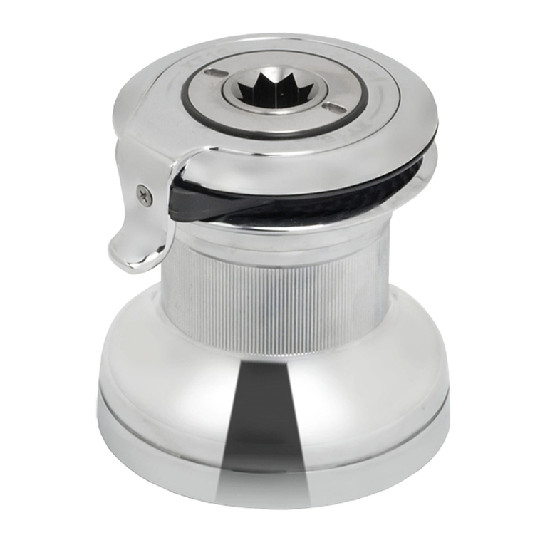
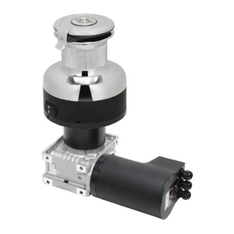
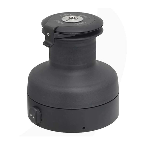
Antal XT40EH User manual

Installation Manual
2 Speed Electric XT Winches
XT40EH
XT44EH
XT48EH
XT52EH
XT62EH
For Models
Antal srl unipersonale, Via del Progresso, 10, 35127, Padova, Italy.
Tel. +39 049 8701265. Fax: +39 049 760906. web: www.antal.it

Installation Manual for Antal 2 Speed Electric XT Winches
Contacts
1. Important Information p. 3
2. Electric System p. 4
3. Table of overall dimensions p. 6
4. Installation p. 7
5. Maintenance of the Winch p. 10
6. Warranty p. 11
Contents
Need the exploded view
drawing of your XT Winch?
Download the full Installation
and maintenance manual from
www.antal.it
Antal srl unipersonale, Via del Progresso, 10, 35127, Padova, Italy.
Tel. +39 049 8701265. Fax: +39 049 760906. web: www.antal.it
XT40EH, XT44EH, XT48EH, XT52EH, XT62EH
Installation and Maintenance
2

1. Important Information
The present Installation Manual contains important information for the
correct use of 2 Speed Electrical XT winches and you are therefore
advised to read it carefully before using the product.
The present manual gives technical information for the installation and
the maintenance of the following XT winch models: XT40EH, XT44EH,
XT48EH, XT52EH, XT62EH. In case of technical queries, contact
These models are equipped with an electric horizontal motor and a
speed reducer with a worm screw.
Electric winches retain two speeds both in manual use (inverting the
direction of rotation of the handle) and in electric use (pressing one of
the two control buttons).
It is of fundamental importance to be able to choose the most suitable
speed for the manoeuvre that you want to perform; this allows fast
recovery of the first part of the manoeuvre and more careful regulation
in the final stage.
In electric winches the speeds are higher than in manual use even if,
at maximum load, a speed reduction up to 30% must be considered.
Speed
Motors with a power of 700 or 1000 Watt are used to drive the winches,
depending on the size of the model. Considering a mean reduction
gear efficiency of 70%, this gives powers of 490 or 700 Watt at winch
intake. It is interesting to compare these figures with the power value
in manual use, which is conventionally considered to be 400 Watt.
Power
Antal powered winches come supplied with a chrome - plated bronze
drum. Black anodized aluminium drums are available on request, in
this case the aluminium drum is “reinforced” applying a special toothed
crowngear of high resistance alloy or chromed bronze.
Winch Drum
Simply insert the handle to disconnect the speed reducer-motor unit.
For Greater Safety: accidental starting of the motor does not affect
the winch, avoiding dangerous turning of the handle.
For Greater Efficiency: the speed reducer-motor unit does not turn in
manual use, avoiding needless friction.
Use
XT40EH, XT44EH, XT48EH, XT52EH, XT62EH
Installation and Maintenance
3

2. Electric System
The thermal switches indicated in the following table have dimensions
calculated to break the circuit in case of exceptional overload; it is
possible to consider thermal relays with a setting at a lower level.
Control Box
Switches - Mod. 251.035
Contains the solenoids for activating the motor in button control
operation.
Breaker
Two switches are needed to activate the two speeds of each winch;
these are conventionally the red one for the first and the grey one for
the second speed.
Although the microswitch is protected by a watertight diaphragm, the
stainless steel ring nut is provided with a seat for sealant; more
sealant must also be put in the hole through which the electric wire
passes.
70
0
I
Ø 54 86
105
64
M1
A1 C A2
+
-M2
23
SEALANT SEALANT
Ø 65
Ø 80
XT40EH, XT44EH, XT48EH, XT52EH, XT62EH
Installation and Maintenance
4

Electric System
Power Cables
Button Cables
The electric system must be installed by specialised personnel, in
compliance with the regulations in force; some general information is
given below.
For the electric diagram directions included in the control box should
be consulted.
The table lists suggested values for the cable sections; these values
must be increased for very long distance or for prolonged use.
2 Recommended section 1.5 to 2.5 mm .
Model Motor
Watt Volt Battery
Amp/H
Cable
mm²
Breaker
Amp
Control
Box
Model
XT40EH
XT44EH
XT48EH
700
12 100/140 30 mod.
A071 70 T6315/12
24 50/70 20 mod.
A041 40 T6315/24
XT52EH
XT62EH 1000
12 150/200 35 mod.
A081 80 T6315/12
24 75/100 25 mod.
A041 40 T6315/24
BATTERY
SPEED 1 SPEED 2
M1
A1 CA2
M2
+
BREAKER
CONTROL BOX
XT40EH, XT44EH, XT48EH, XT52EH, XT62EH
Installation and Maintenance
5

3. Table of overall dimensions
Line Recovery Speed
Recovery speed are indicative values, theoretically calculated without
considering the real installation moreover a speed reduction has to
be considered in the presence of load about 30% reduction under the
max load.
50
DS 120
HW
64
263
DW
Ø125
Ø115
63
DS 120
HW
80
311
DW
205 Ø125
Ø115
XT40EH
XT44EH
XT48EH
XT52EH
XT62EH
189
Model Motor
Watt
Speed - m/min
1 2
SWL
kg
Weight
kg
Deck
Screws
No. x Ø
DS
mm
HW
mm
DW
mm
XT40EH 700 18.0 6.0 800 17.9 5 x 8 140 172 154
XT44EH 700 12.0 5.5 900 20.6 6 x 8 147 202 173
XT48EH 700 9.5 5.0 1000 22.4 6 x 8 156 214 182
XT52EH 1000 16.0 4.6 1200 29.3 6 x 8 174 233 204
XT62EH 1000 13.0 4.0 1400 31.1 6 x 8 194 235 224
XT40EH, XT44EH, XT48EH, XT52EH, XT62EH
Installation and Maintenance
6

4. Installation
F
F1
F2
Ø=120 mm
F3
Motor Unit
XT44ELH, XT48ELH, XT52ELH, XT62ELH
Valid for models:
XT44EH, XT48EH,
XT52EH, XT62EH
1Opening the Winch
First of all, unscrew the upper
ring (R) with the provided key
(K). Thus lift the drum (D) to
access the anchoring holes
on the skirt (S) of the winch.
Winch Motor Disassembly
Disassemble the new Winch
XT-EH:
After lifting the Drum (D), it
is possible to remove the
skirt (S) of the winch from the
flange (F), unscrewing the 6
screws F1.
Remove the Motor Unit:
Remove the Motor Unit from
the flange (F), unscrewing
the screws F2.
Install XT-EH
Drill the deck:
Drill the deck (Ø = 120 mm)
to let the reduction-gear
motor unit through.
Fix the Motor:
Thus, fix the flange F on the
deck with 6 anchoring screws
F3 from above (not supplied
by Antal). Finally Install the
Motor Unit screwing in the F2
screws.
2
3
K
R
S
D
Installation and Maintenance
7

K
R
S
F
F1
F2
Ø=120 mm
F3
Motor Unit
D
Opening the Winch
First of all, unscrew the upper
ring (R) with the provided key
(K). Thus lift the drum (D) to
access the anchoring holes
on the skirt (S) of the winch.
1
Winch Motor Disassembly
Disassemble the new Winch
XT40EH:
After lifting the Drum (D), it
is possible to remove the
skirt (S) of the winch from the
flange (F), unscrewing the 5
screws F1.
Remove the Motor Unit:
Remove the Motor Unit from
the flange (F), unscrewing
the screws F2.
Install XT40EH
Drill the deck:
Drill the deck (Ø = 120 mm)
to let the reduction-gear
motor unit through.
Fix the Motor:
Thus, fix the flange F on the
deck with 5 anchoring screws
F3 from underneath (not
supplied by Antal). Finally
Install the Motor Unit screwing
in the F2 screws.
2
3
Valid for model:
XT40EH
Installation and Maintenance
8
XT40ELH

Winch Assembly
Reassemble the winch, inverting the operations described above in
points 2 and 1. Fix the motor unit to the sub-base, tighten the 8 scews
F2 so that the Motor Unit matches perfectly to the flange (F).
4
Ensure that the drainege holes of the sub-base are facing in the right
direction.
Seal the holes for the anchoring screws and the join between the
skirt and the deck with silicone.
Seal this join with a silicone gasket (such as Motorsil Arexons).
Caution - The weight of the motor unit must be supported from below
so as to distribute its tension correctly on the screws F2, the uneven
distribution of the unit’s weight could cause it to tilt with respect to the
flange F, jeopardising perfect coupling and therefore the operation of
the electric winch.
For the same reason the motor unit must not «touch» the deck or the
structures below it.
Lubrication
During assembly all the steel screws and washers must be generously
greased to avoid corrosion phenomena in the areas in contact with
aluminium parts.
Antal supplies a special grease for marine applications:
HDR in 150 gr packs.
This product is an excellent lubricant and ensures lasting protection of
the aluminium against corrosion phenomena.
5
NO OK S
MOTOR
UNIT
F2
XT40EH, XT44EH, XT48EH, XT52EH, XT62EH
Installation and Maintenance
9

Frequent maintenance. All XT winches should be washed frequently,
and in any case after each use, to avoid the accumulation of salt. Use
plenty of fresh water and clean it on all visible surfaces. Ensure the
cleaning of the drainage channels placed at the bottom of the winch,
to avoid water stagnation.
Complete maintenance. With seasonal frequency XT winches should
be inspected visually inside.
Parts in need of maintenance. The most relevant parts are those
subject to movement and rubbing. These are the roller bearings, the
gears and pawls, the stem and the inside of the drum. For the complete
maintenance of the winch, disassemble the winch in order to access
the relevant parts.
Hydrolub Antal Grease. We recommend the use of Antal Grease, a
grease expecially made for lubrication of winches and protection of
aluminum parts in the marine environment (Mod. HDR).
Cleaning. Remove old lubricant. In order to do so use a soft bristle
brush and solvent (use diesel in case you do not have other solvents).
Lubrication. It increases the performance and prolongs the life
of the winch. Also, it prevents the natural accumulation of salt
to obstruct the inner mechanism. Also, if you are using the HDR
Antal Grease, it also protects the aluminum parts from galvanic
corrosion, too.
Thus we advise to put a thin layer of HDR Antal Grease; not only to
lubricate all moving parts, but also to protect the aluminum surfaces in
contact with s.steel parts, e.g. screws.
Kit Winch. Antal provides a repair kit winch containing pawls and
springs (Mod. XTKIT).
Important Concepts
All detailed information about Maintenance are
contained in the Installation and Maintenance Manual
of the XT Winches. To download the manuals, go on
internet at the winch page, or digit www.antal.it
5. Maintenance of the Winch
The complete maintenance includes the opening of the winch,
the cleaning of the parts from old lubricants and the new lubrication
of all moving parts.
XT40EH, XT44EH, XT48EH, XT52EH, XT62EH
Installation and Maintenance
10

Antal guarantees its equipment to be free of defects in material and
workmanship for 3 years from the date of purchase. During this period
defective parts will be repaired or replaced by Antal. Warranty does
not cover: products incorrectly installed; products used in applications
for which they are not intended; products used under loads exceeding
the product’s stated loads; products not properly maintained. Also,
warranty does not cover defects due to corrosion, U-V degradation,
and normal wear and tear.
Products subject to warranty claim will be returned to Antal for
examination and possible repairing or replacement. Antal is not
responsible for installation or shipping costs.
6. Warranty
XT40EH, XT44EH, XT48EH, XT52EH, XT62EH
Installation and Maintenance
11
This manual suits for next models
4
Table of contents
Other Antal Winch manuals