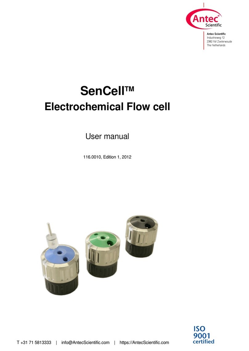
Antec Scientific FlexCell User manual

T +31 71 5813333 | info@ AntecScientific.com | https://AntecScientific.com
Antec Scientific
Industrieweg 12
2382 NV Zoeterwoude
The Netherlands
FlexCellTM
Electrochemical flow cell
User manual
102.0010A, Edition 9, 2017

Copyright ©2016, Antec Scientific, The Netherlands. Contents of this publication may not be reproduced in
any form or by any means (including electronic storage and retrieval or translation into a foreign language)
without prior agreement and written consent from the copyright of the owner. Information in this publication
is subject to change and does not represent a commitment on the part of Antec Scientific. Antec Scientific
reserves the right to make changes to the design and specifications of the instrument and the contents of
this manual without prior notice.
ROXY, ALEXYS, DECADE, DECADE II, DECADE Elite, DECADE Lite, INTRO, FlexCell, ReactorCell,
ISAAC, HyREF, SenCell and SynthesisCell are trademarks of Antec Scientific. Whatman™ (word and
device) and Whatrnan™ (word only) are trademarks of Whatman lnternational Ltd. SOLVENT IFD™ and
AQUEOUS IFD™ are trademarks of Arbor Tech-nologies, Inc. Clarity®, DataApex® are trademarks of
DataApex Ltd. Microsoft® and Windows™ are trademarks of Microsoft Corporation. Excel is a registered
trademark of the Microsoft Corporation. All other trademarks are the property of their respective owners.
The software and the information provided herein is believed to be reliable. Antec Scientific shall not be
liable for errors contained herein or for incidental or consequential damages in connection with the
furnishing, performance, or use of this software or this manual. All use of the software shall be entirely at the
user’s own risk.

. 1
.
Symbols
The following symbols are used in this guide:
The warning sign denotes a hazard. It calls attention to a
procedure or practice which, if not adhered to, could result
in severe injuryor damage or destruction of parts or all of
the equipment. Do not proceed beyond a warning sign until
the indicated conditions are fully understood and met.
The caution sign denotes a hazard. It calls attention to a
procedure or practice which, if not adhered to, could result
in damage or destruction of parts or all of the equipment
and/or erratic results. Do not proceed beyond a cautions
sign until the indicated conditions are fullyunderstood and
met.
The biohazard sign draws attention to the fact that use
of biological materials, viral samples may carry a signifi-
cant health risk.
The toxic hazard sign draws attention to the fact that use
of toxic solvents or samples may carrya significant
health risk.
The attention sign signals relevant information. Read this
information, as it might be helpful.
The note sign signals additional information. It provides
advice or a suggestion that may support you in using the
equipment.

2 FlexCell user manual, edition 9
Intended use
The FlexCell is used in combination with an Antec Scientific Electrochemical
Detector (for example DECADE, INTRO, DECADE II or DECADE Elite/Lite in
(Ultra) High Performance Liquid Chromatography for the electrochemical
detection of suitable analytes in liquid samples. (U)HPLC is a method for
separating substance mixtures, determining substances and measuring their
concentration.
Electrochemical detection is a specific measuring technique with which the
amount of electroactive substances in a liquid sample can be quantified. This
technique can be used for the chromatographic analysis of a wide range of
electroactive analytes in the fields of for example:
•Biochemistry/bioanalytical analyses
•Chiral analyses
•Food analyses
•Environmental analyses
•Clinical analyses (research purpose only)
Operation of the flow cell may involve the use of hazardous materials
including corrosive, toxic or flammable liquids. The flow cell should only be
used by end-users with the following expertise:
•Completed degree as chemical laboratorytechnician or comparable
vocational training
•Fundamental knowledge of liquid chromatography
•Participation in an installation of the system performed bythe
manufacturer or a companyauthorized bythe manufacturer and
suitable training on the system and chromatography software.
•Knowledge and experience in the safe handling of toxic and
corrosive chemicals and knowledge of the application of fire
prevention measures prescribed for laboratories.
Information on safety practices are provided in the user manual and/or quick
start guides. Before using your flow cell or accessories, you must thoroughly
read the manual and safety practices. This manual is written for trained
laboratory technicians who use the flow cell in combination with an
electrochemical detector for (U)HPLC analysis.
For research purpose only. While clinical applications may be shown,
this instrument is not tested by the manufacturer to comply with the In
Vitro Diagnostics Directive.

. 3
WEEE directive
All equipment of Antec Scientific which are subjected to the WEEE directive
shipped after August 13, 2005 are compliant with the WEEE marking
requirements. Such products are labelled with the “crossed out wheelie”,
depicted on the left site.
Shipping address for the end-of-life products:
Antec Scientific
Industrieweg 12
2382NV Zoeterwoude
The Netherlands
In case of questions, or if further information is required about the collection
& recycling procedure, please contact your local distributor.
Unskilled, improper, or careless use of this products can create
hazards which could result in personal injury, death or severe damage
to equipment and property. Observe all relevant safety practices at all
times. Only use the device for applications that fall within the scope of
the specified intended use.
The symbol on the product indicates that the product must not be
disposed as unsorted municipality waste.
Collection & recycling information
Please ship the instrument back to the manufacturer (Antec Scientific,
the Netherlands) at the end-of-life time of the product. The
manufacturer will take care of the proper disposal and recycling of the
instrument at its facilities.

4 FlexCell user manual, edition 9
Safety instructions
Adhere to the following guidelines when using the electrochemical flow cell.
These safety practices are intended to ensure safe operation.
This hardware should be used by trained laboratory personnel only
with a completed degree as chemical laboratory technician or
comparable vocational training. The operator should have fundamental
knowledge of liquid chromatography.
Use proper eye and skin protection when working with solvents.
Additional safety requirements or protection may be necessary
depending on the chemicals used in combination with this equipment.
Make sure that you understand the hazards associated with the
chemicals used and take appropriate measures with regards to safety
and protection.
Working environment & safety
The intended use of the flow cell is to detect electroactive substances in
liquid samples in combination with a (U) HPLC-ECD system in a laboratory
environment. Operators using the system should have the appropriate
education an extensive understanding of (U)HPLC and electrochemical
detection and be skilled in the art.
Using the flow cell in other ways than indicated in the manual or
defined by good laboratory practice may result in erratic or unsafe
operation.

. 5
Operation
To assure optimal performance keep of the flow cell we recommend that the
cell is checked regularlyand maintenance procedures are carried out.
Preventive maintenance contracts and a factorycell refurbish service are
available for that Purpose. Please contact your local dealer for more
information.
Solvents
The solvents used maybe flammable, toxic or corrosive. The room in which
the flow cell and system is installed should be well ventilated to prevent that
solvent vapors cause poisoning or ignite and cause a fire. Use of open fire in
the vicinityof this flow cell and system must be strictlyprohibited. Do not
install the flow cell and system in the same room with anyother equipment
that emits or could potentiallyemit sparks. Provide protective equipment near
the instrument, when solvent gets into the eyes or on the skin, it must be
flushed away immediately. Provide equipment, such eye wash stations and
safety showers, as close to system as possible.
Use proper eye and skin protection when working with solvents. Additional
safety requirements or protection may be necessarydepending on the
chemicals used in combination with this equipment. Make sure that you
understand the hazards associated with the chemicals used and take
appropriate measures with regards to safety and protection.
Sample containers (vials) should be sealed to minimize any risks related to
solvent vapor.
Biological Hazard
When you analyze biological fluids you need possible precautions and treat
all specimens as potentially infectious. Always wear protective
And gloves when handling toxic or biologically infectious samples to prevent
bio hazards or hazards while working with the flow cell. If necessary the flow
cell must be decontaminated before decommissioning or shipment of the cell
for repair to Antec Scientific or its representatives. When shipped to Antec
Scientific every cell has to be accompanied with a decontamination form
which should be completely filled in and signed by the customer. Without this
decontamination form the flow cell will not be processed by Antec Scientific
(either repaired or disposed).
Waste disposal
Perform periodic leak checks on LC tubing and connections. Do not close or
block the drain in the oven compartment. Do not allow flammable and/or
toxic solvents to accumulate. Follow a regulated, approved waste

6 FlexCell user manual, edition 9
Disposal program. Never dispose of flammable and/ toxic solvents through
the municipal sewage system.
Applications: quality control
It is recommended that you routinelyrun several quality control samples.
Qualitycontrol samples should represent low, average and high levels of a
compound. Make sure that quality control sample results are within
An acceptable range, and evaluate precision from day to dayand run to run.
Data collected when quality control samples are out of range may not be
valid. Do not report this data until you are certain that system
Performance is acceptable. Apart from use of quality control samples, we
Recommend that you use blanks. The blanks will help you assess whether
carry-over is within an acceptable range and monitor the integrity of your
data.
Laboratory regulations
Observe national and international regulations pertaining to laboratorywork!
For example:
•Good Laboratory Practice (GLP) of the American Food & Drug
Administration
•For development of methods and validation of devices:
•Protocol for the Adoption of Analytical Methods in the
•Clinical Chemistry Laboratory, American Journal of Medical
Technology, 44, 1, pages 30–37 (1978)
•Accident prevention regulations published bythe accident insurance
companies for laboratory work
Spare parts and service availability
Manufacturer provides operational spare parts of the instrument and current
accessories for a period of five years after shipment of the final production
run of the instrument. Spare parts will be available after this five years period
on an ‘as available’ basis.
Manufacturer provides a variety of services to support her customers after
warranty expiration. Repair service can be provided on a time and material
basis. Contact your local supplier for servicing. Technical support and training
can be provided by qualified chemists on both contractual or as-needed
basis.

. 7
Table of contents
Symbols...............................................................................................1
Safety instructions...............................................................................4
Spare parts and service availability.....................................................6
Table of contents.................................................................................7
CHAPTER 1.................................................................................................9
The electrochemical flow cell........................................................................9
Introduction..........................................................................................9
The three-electrode configuration.......................................................9
Requirements and limitations ...........................................................11
Working electrodes...........................................................................11
Reference electrode: HyREF™ ........................................................13
Reference electrode: salt bridge Ag/AgCl........................................14
Reference electrode: ISAAC™ .........................................................15
CHAPTER 2...............................................................................................17
General precautions.....................................................................................17
CHAPTER 3...............................................................................................18
Installation.....................................................................................................18
Connecting a FlexCell to an LC system ...........................................18
CHAPTER 4...............................................................................................20
Maintenance..................................................................................................20
Disassembly of the flow cell..............................................................20
Working electrode cleaning ..............................................................22
Polishing a working electrode...........................................................22
Flattening a metal working electrode................................................23
HyREF & ISAAC reference electrodes.............................................23
Salt bridge Ag/AgCl reference electrode..........................................23
Salt bridge Ag/AgCl reference electrode check................................24
Refilling a salt bridge Ag/AgCl reference electrode..........................25
Refritting a salt bridge Ag/AgCl reference electrode........................26
Assembly of the flow cell...................................................................27
Storage..............................................................................................28

8 FlexCell user manual, edition 9
CHAPTER 5...............................................................................................29
Specifications................................................................................................29
CHAPTER 6...............................................................................................30
Part list...........................................................................................................30

CHAPTER 1 The electrochemical flow cell 9
C H A P T E R 1
The electrochemical flow cell
Introduction
The FlexCell™(Fig. 1) has been developed for analysis in standard and
microbore LC-EC with an effective volume of only 0.5 µL. A range of different
working electrode materials are available for the FlexCell and they are easily
exchangeable, offering maximum flexibility for running various applications.
Also, in applications where the working electrode material is
electrochemically ‘consumed’ the option for an easy exchange is
advantageous. Exchanging the working electrode only takes a minute.
Fig. 1. FlexCell
The three-electrode configuration
In the FlexCell a three-electrode configuration is used (Fig. 2). The working
potential is set between the working electrode (WE) and the auxiliary
electrode (AUX). The auxiliary electrode is kept at the same precisely defined
potential as the reference electrode (REF) by means of the so-called voltage
clamp. This is an electronic feedback circuit that compensates for
polarisation effects at the electrodes. At the working electrode, which is kept
at virtual ground, the electrochemical reaction takes place, i.e. electrons are
transferred at the working electrode. This results in an electrical current to the
I/E converter, which is a special type of operational amplifier. The output

10 FlexCell user manual, edition 9
voltage can be processed by an integrator, recorder or AD convertor to
generate the chromatogram.
Fig. 2. Schematic representation of an electrochemical cell with a three-
electrode configuration.
Essentially, for the oxidation or reduction reaction it would be sufficient to use
onlytwo electrodes. However, the three-electrode configuration has several
advantages over a two-electrode configuration:
•If the working potential would be applied only over an auxiliary
electrode versus the working electrode (without reference electrode),
the working potential would continuouslychange due to polarisation
effects at the electrodes, resulting in highlyunstable working
conditions.
•If the working potential would be applied only over the reference
electrode versus the working electrode (without auxiliaryelectrode),
the working potential would be verywell defined. However, the
potential of a reference electrode is only well defined if the current
drawn is extremely low (pico-amperes) resulting in a very limited
dynamic range.
A three-electrode configuration combines the best of both configurations. The
reference electrode stabilises the working potential and the auxiliary
electrode can supply high currents. This results in the tremendous dynamic
range of a three-electrode system.

CHAPTER 1 The electrochemical flow cell 11
Requirements and limitations
Ions in running solution
For the three-electrode configuration to work, the solution inside the flow cell
should have a low electrical resistance. This is secured by running solution
through the flow cell containing at least 10 mM ions.
The solution running through the flow cell should have an ionic
strength of at least 10 mM when the cell is ON.
Either the mobile phase contain the ions (usuallythe pH buffer) or the ions
have to be added in a post-column set-up. The absence of ions in the
solution running through the flow cell results in a destabilisation of the feed-
back loop and potential damage to the electrodes. When the flow is not yet
filled (air has high electrical resistance), or solutions without ions are being
flushed through, the cell should be OFF.
Organics in running solution
The effective volume of the cell is defined by the working electrode pressing
on the inlet block with a spacer in between. Running solutions through the
flow cell that contain more than 50% organic solvents increases the
occurrence of leakage: the organic solvent makes the solution creep under
the spacer. For such applications, a different cell design is better suited.
Working electrodes
Various useful materials
The surface of the working electrode is where the electrochemical reaction
takes place. This puts specific demands on the working electrode material. It
should be made of an (electro-)chemicallyinert material, it should have a
very well defined and flat surface, and it should have favourable I/E
characteristics for the analyte of interest. Ideally, a high signal is obtained at a
low working potential as noise levels increase with potential.
For the FlexCell, different working electrode materials are available: glassy
carbon, gold, silver, platinum, Boron Doped Diamond (BDD), and copper. For
most regular applications, glassy carbon will be the working electrode
material of choice. Some components are best detected on specific

12 FlexCell user manual, edition 9
materials. For example, the analysis of iodide is best done on a silver
working electrode. This reaction alreadyoccurs at a very low working
potential (1 mV !), which results in an extremely high selectivity. This allows
the determination of iodide in urine samples with virtually no sample pre-
treatment.
Applications
The typical application for specific working electrode materials is given in
Table I. Different materials also have different working potential limits: at high
positive working potentials, the water in the mobile phase electrolyses and
results in a strong increase of the background current and noise. At negative
potentials, the use of platinum electrodes is stronglylimited by the specific
ease of reducing hydrogen ions to hydrogen gas. For metal electrodes, the
formation of metal oxides is a limiting factor for running oxidative
measurements.
Table I. Some features of different working electrode (WE) materials.
WE material
Limits of working potential vs. Ag/AgCl (V)
Application example
alkaline
acidic
Glassy carbon
-1.50
+0.60
-0.80
+1.30
catecholamines
Gold
-1.25
+0.75
-0.35
+1.10
Carbohydrates, thiols
BDD
-1.00
+2.00
iodide, disulfides, phenols
Platinum
-0.90
+0.65
-0.20
+1.30
alcohols, glycols
Silver
-1.20
+0.10
-0.55
+0.40
halides, cyanide
Copper
-
+0.20
-
+0.60
amino acids, carbohydrates
Boron Doped Diamond (BDD) electrodes
Boron Doped Diamond (BDD) is the most recent addition to the list of
available FlexCell working electrode disks. The BDD electrode consisting of
an ultra-thin film of boron doped diamond material deposited on a Si-wafer.
The electrode is anodized and has the property to detect oxidized
components at 1.5- 2 V that would otherwise need a reductive step before
detection under oxidative conditions. Other special properties of BDD
electrodes are inertness and excellent response stabilitythat make it well
suited to detect phenols where electrode fouling is an issue when glassy
carbon would be used.
Chemical compatibility: the BDD electrode operational lifetime is strongly
reduced when exposed to fluorinated acids, such as tri-fluoroacetic acid.
Even at relativelylow concentrations (2% in aqueous solution) significant
damage of the diamond electrode was seen within days of operation.

CHAPTER 1 The electrochemical flow cell 13
Reference electrode: HyREF™
The is most commonly used reference electrode for a FlexCell is the
maintenance-free HyREF. This reference electrode is most suitable for use
with high concentrations (>20%) of organic modifier in the mobile phase or
when running alkaline mobile phase. An important characteristic of the
HyREF is the pH dependence of the reference potential.
It is important to realise that if the pH of the mobile phase is changed,
the optimum working potential also changes. In such a case it is
advisable to construct a hydrodynamic voltammogram to find the new
optimum.
HyREF has a pH dependent reference potential
When comparing the reference potential of a HyREF with a saltbridge
(Ag/AgCl), a pH dependent difference can be observed (Fig 3.). Therefore, it
is important to make sure to work with a well buffered mobile phase when
using the HyREF. Otherwise, the reference potential will not be a fixed value.
Lineaire regressie (W=1)
0
100
200
300
400
0
5
10
15
pH
Fig. 3. Difference in reference potential when comparing HyREF with
saltbridge Ag/AgCl REF at different mobile phase pH.
pH E (V)
3.3 232
6.2 130
7.5 90
11.8 0

14 FlexCell user manual, edition 9
Reference electrode: salt bridge Ag/AgCl
The salt bridge Ag/AgCl reference electrode consists of a small container,
with a solid AgCl coated silver rod immersed in a solution of saturated KCl
(Fig. 4). This type of reference electrode needs regular maintenance.
Electrical contact with the other two electrodes in the flow cell is made
through a wetted cotton wool frit (the salt bridge), which is electrically
conducting and slows down the leakage of KCl
Fig. 4. Schematic representation of the saltbridge Ag/AgCl reference
electrode.
Three aspects determine the proper function of an Ag/AgCl reference
electrode.
1. The chloride concentration must be kept at a strictlyfixed level. This is
best guaranteed byusing a saturated chloride salt solution at a constant
temperature.
2. Absence of air bubbles inside or close to the salt bridge give the best
stabilityof the three-electrode configuration.
3. The salt bridge must allow proper electrical contact with the mobile
phase.
For certain applications, another chloride salt is to be preferred:
•In case of perchlorate containing mobile phases, NaCl instead of KCl
is to be used, as potassium perchlorate will precipitate and clog the
cotton wool frit.
•At high levels of organic modifier in the mobile phase, the chamber
must be filled with lithium chloride solution instead of KCl to prevent
precipitation at the interface.

CHAPTER 1 The electrochemical flow cell 15
Reference electrode: ISAAC™
The In Situ Ag/AgCl (ISAAC) reference electrode is the low-maintenance
version of the Ag/AgCl saltbridge reference electrode.
The potential of an ISAAC is defined by the concentration of chloride ions in
the mobile phase. Therefore, everynew batch of mobile phase should be
prepared with the same concentration of chloride ions (typically2 mM) to
get reproducible results.
It is important to add a fixed concentration of chloride ions to the
mobile phase when using the ISAAC as a reference electrode. Without
chloride ions in the mobile phase, the ISAAC gives erratic results.
ISAAC has a chloride dependent reference potential
When comparing the reference potential of an ISAAC with a saltbridge
(Ag/AgCl), a chloride dependent difference can be observed (Table II). For
example, the difference in reference potential between the saltbridge
Ag/AgCl reference electrode with saturated KCl, and the ISAAC with 2 mM
chloride ions in the mobile phase is 189 mV.
Fig. 5. The Ag/AgCl reference potential is dependent of the chloride
concentration. The relationship between potential and other chloride
concentrations is described with the equation Ecell = EoAgCl - (RT/F) ln [Cl-]
where R is the gas constant (8.314 J.mol-1K-1), T is the absolute temperature
(293 K) and F is the Faraday constant (96485 C/mol). The EoAgCl (in 1.0 mol/l
Cl-solution) for the half-reaction AgCl(s) + e- <=> Ag(s) + Cl-is 0.222 V.

16 FlexCell user manual, edition 9
Table II. Potential of the Ag/AgCl reference electrode. A saltbridge Ag/AgCl
reference is loaded with saturated KCl and the ISAAC is in contact with the
concentration of chloride added to the mobile phase. dE is the potential
difference compared to EAg/AgCl in saturated KCl (3500 mM Cl-).
Cl-
(mmol/l)
E Ag/AgCl
(mV)
dE
(mV)
3500 190 0
2500 199 8
1500 212 21
500 240 49
100 280 90
20 321 130
10 338 148
8344 154
6351 161
4361 171
2379 189
1396 206
0.5 414 224
Restriction for using the ISAAC
A high working potential (> 1.2 V vs. Ag/AgCl in 2 mmol/l KCl) will oxidize Cl-,
which then contributes to the background current and noise.
In ion chromatography the addition of Cl-maylead to undesired
chromatographic changes.
When using a silver working electrode, the addition of Cl-to the mobile phase
will cause formation of an AgCl coating on the working electrode, leading to
inactivation.
At high pH or high modifier concentrations the HyREF is more suitable.

CHAPTER 2 General precautions 17
C H A P T E R 2
General precautions
1. The flow cell is assembled properly when it arrives. Make sure that all
marked items on the checklist are included.
2. Always make sure that the surfaces of the spacer and working electrode
are dry and free from particulate matter before assembling the cell.
3. Clean fingerprints from spacer and electrode surfaces with a soft tissue
soaked in acetone or methanol. If the auxiliaryelectrode needs to be
cleaned, do not apply force to prevent damaging the electrode surface.
4. Except for BDD electrodes, make sure that the working electrode has a
mirror-like appearance before installation.
The BDD electrode has a thin crystalline blue/greyish surface. This
electrode should not be polished. Polishing this electrode will damage
the active surface and lead to loss of performance.
5. If the flow cell is not in use and removed from the LC system, we
recommend that you disassemble the cell and clean all surfaces.
The construction of the FlexCell is such that both fluid connections can
be used as in- or outlet.
Never switch on the flow cell if:
•the (black, red and blue) cell cable is not correctly connected
•the cell is only partly (or not at all) filled with mobile phase
•the cell is filled with solutions that do not contain electrolytes
as damage to the working electrode or the electronics may occur.
The ISAAC reference electrode requires the presence of 2 mM chloride
ions (KCl or NaCl) in the mobile phase. Add and equilibrate before
installation.
Use proper eye and skin protection when working with solvents.

18 FlexCell user manual, edition 9
C H A P T E R 3
Installation
The maximum detection stabilityis attained when not only the flow cell, but
also the HPLC column is incorporated in the detector oven. The detector has
an integrated Faraday cage and an accurate temperature controlled oven
compartment ensuring stable working conditions. Installing the flow cell and
column within such a controlled environment is the minimum requirement for
high-quality LC-EC trace analyses.
Connecting a FlexCell to an LC system
1. Install a suitable length of sharply cut 1/16” OD PEEK tubing to the
column outlet. Choose a tubing ID that matches the column ID:
- 0.25 mm ID for working with normal bore columns
- 0.13 mm ID for working with mini bore columns
- 64 µm ID for narrow bore columns
2. Keep some tissues close by as you probably will spill some mobile phase
during the mounting procedure. Remove the reference electrode from the
inlet block (Fig. 1).
3. With the mobile phase running from the column, connect the column
outlet to the flow cell inlet, using one of the supplied connectors and
tighten it carefully. Over-tightening affects the flow through the tubing
(turbulence) and decreases the flow cell performance.
Use only our factory-supplied finger tight connectors at the flow cell;
other connectors may cause serious damage!
4. Install a suitable length of sharply cut 0.5 mm ID PEEK tubing to the flow
cell outlet.
5. In case of a salt bridge reference electrode, first make sure it is ready for
use:
When using a salt bridge reference electrode, inspect it visually before
installation:
- no air bubbles trapped in the body
- visual presence of salt crystals in the body
- the cotton tip looks white and wet
Apply maintenance if necessary (see next chapter).
Table of contents
Other Antec Scientific Security Sensor manuals
Popular Security Sensor manuals by other brands

Bin Master
Bin Master NCR-30 operating instructions

Hellermann Tyton
Hellermann Tyton TopTronic T175HP manual

C.P. Electronics
C.P. Electronics MWS5-DD-SA-C installation guide

Master cool
Master cool Intella Sense 55800 operating instructions

HIK VISION
HIK VISION DS-PDMCX-E-WE quick start guide

Green Brook
Green Brook Orion Range OD102 Important safety instructions