RS485 communication interface
Databits: 8
Parity: none
Stop bits: 1 or 2
Protocol: Modbus RTU
Supported Modbus functions:
03 - read multiple registers
06 - write single register
Modbus registers (0-based, decimal format)
Reg Description Supported values
1Hardware version read only
2Software version read only
3Product serial number read only
4Slave ID (network address)* 1...247, default 1
5Baudrate* 1200...57600 baud, default 9600
6Response delay, ms 10...255 ms, default 10
7Stop bits* 1 / 2, default 1
17 Restart write ‘42330’ for soft restart
162 Temperature shift adjustment -32000...+32000 T units (0,01 °C)
165 Gas channel shift adjustment -32000...+32000 gas units, default 0
166 Gas channel slope adjustment 1...65535, default 512
167 Output change rate limit 1...32000 gas units/s, 0=no limit
168 Integrating filter time constant 1...32000 s, 0=no integrating filter
201 Parameter assigned to OUT1 0=none, 1=T, 2=gas, 9=forced by 203
202 Parameter assigned to OUT2 0=none, 1=T, 2=gas, 9=forced by 204
203 Forced value for OUT1 0...1000 (0.0...100.0% of full scale)
204 Forced value for OUT2 0...1000 (0.0...100.0% of full scale)
211 Parameter assigned to RE1 0=none, 1=T, 2=gas, 9=forced by 213
212 Parameter assigned to RE2 0=none, 1=T, 2=gas, 9=forced by 214
213 Forced state for RE1 0=off, 1=on (relay control by Modbus)
214 Forced state for RE2 0=off, 1=on (relay control by Modbus)
215 Switch delay for RE1 0...1000 s, default 0
216 Switch delay for RE2 0...1000 s, default 0
217 Min on/off time for RE1 0...1000 s, default 0
218 Min on/off time for RE2 0...1000 s, default 0
219 Control logic for relay RE1 0:_, 1:_↓↑¯, 2:¯↑↓_, 3:_↑¯↓_, 4:¯↓_↑¯
220 Control logic for relay RE2 0:_, 1:_↓↑¯, 2:¯↑↓_, 3:_↑¯↓_, 4:¯↓_↑¯
221 LOW setpoint for relay RE1 -32000...+32000, gas or T units
222 HIGH setpoint for relay RE1 -32000...+32000, gas or T units
223 LOW setpoint for relay RE2 -32000...+32000, gas or T units
224 HIGH setpoint for relay RE2 -32000...+32000, gas or T units
258 Measured temperature -4000...+12500 T units (0,01 °C)
259 Gas concentration 0...65535 gas units
261 0% value of OUT1 -32000...+32000 gas units / integer °C
262 100% value of OUT1 -32000...+32000 gas units / integer °C
263 0% value of OUT2 -32000...+32000 gas units / integer °C
264 100% value of OUT2 -32000...+32000 gas units / integer °C
* - the new value is applied after restart
Broadcast ID=0 may be used to assign a new ID to device with unknown ID
E2608-NH3_UM_EN Rev 18.02.2016
Specifications
Detection range 0...1000 ppm NH3
Resolution 1 ppm NH3
Accuracy ± 5 ppm NH3
Response time ~10 seconds
Warm-up time ~2 minutes , depending on
unpowered period and atmosphere
Sensor type semiconducting metal-oxide
lifetime > 5 years
Sampling method diffusion
Analog outputs 2 × 4-20 mA or 0-10 V
Load resistance
for 4-20 mA output mode: RL< (Us- 3V) / 22 mA
for 0-10 V output mode: RL> 100 kOhm
Operating conditions -30...+70 °C, 0...99 %RH
Power supply 11...30 VDC
with integrated mains supply module 90...265 VAC
Power consumption < 2 VA
Electromagnetic compatibility according to 2004/108/EEC,
2014/30/EU and EN61326-1 requirements
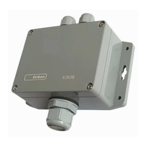
Wall-mount enclosure oyster white ABS 82×85×55 mm, IP65
Relays 2 × SPST, max 5A, 30 VDC / 250 VAC
Factory settings
Target gas Ammonia NH3
Gas units ppm
OUT1 assignment and scale 2: gas, 0 - 1000 ppm
OUT2 assignment and scale 2: gas, 0 - 1000 ppm
RE1 assignment and logic 2: gas, 1: on at high values
RE1 HIGH setpoint (set) 25 ppm
RE1 LOW setpoint (release) 20 ppm
RE2 assignment and logic 2: gas, 1: on at high values
RE2 HIGH setpoint (set) 35 ppm
RE2 LOW setpoint (release) 28 ppm
Tel +372 733 6310 51014 Estonia www.evikon.eu
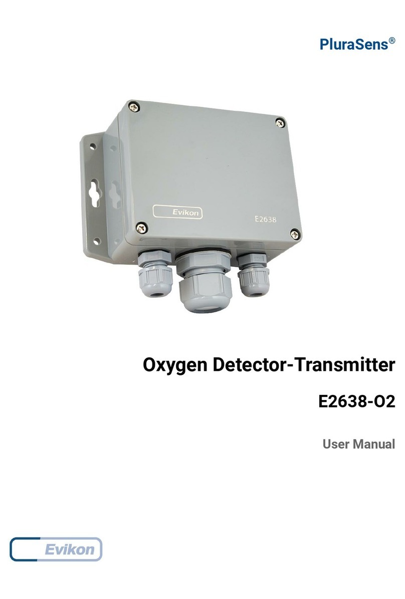
PluraSens®
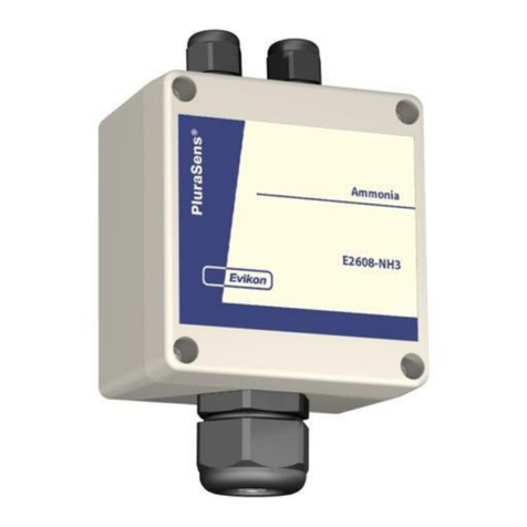
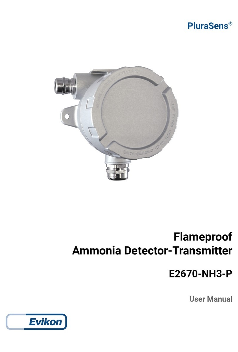
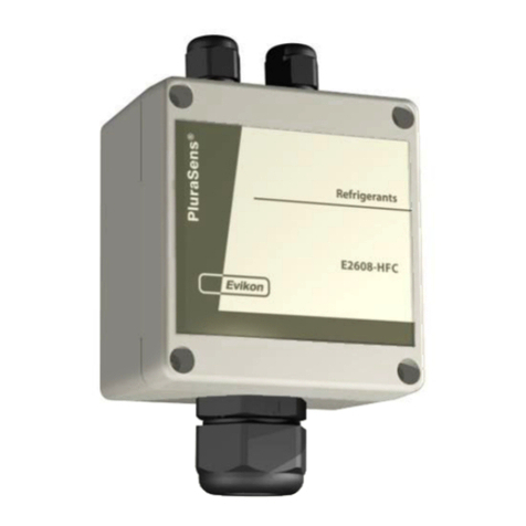
Ammonia Detector-Transmitter
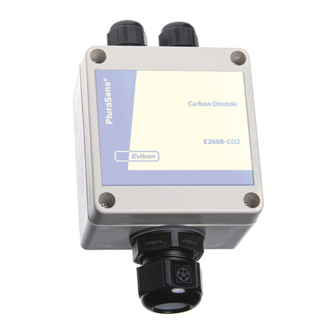
E2608-NH3
User Manual

