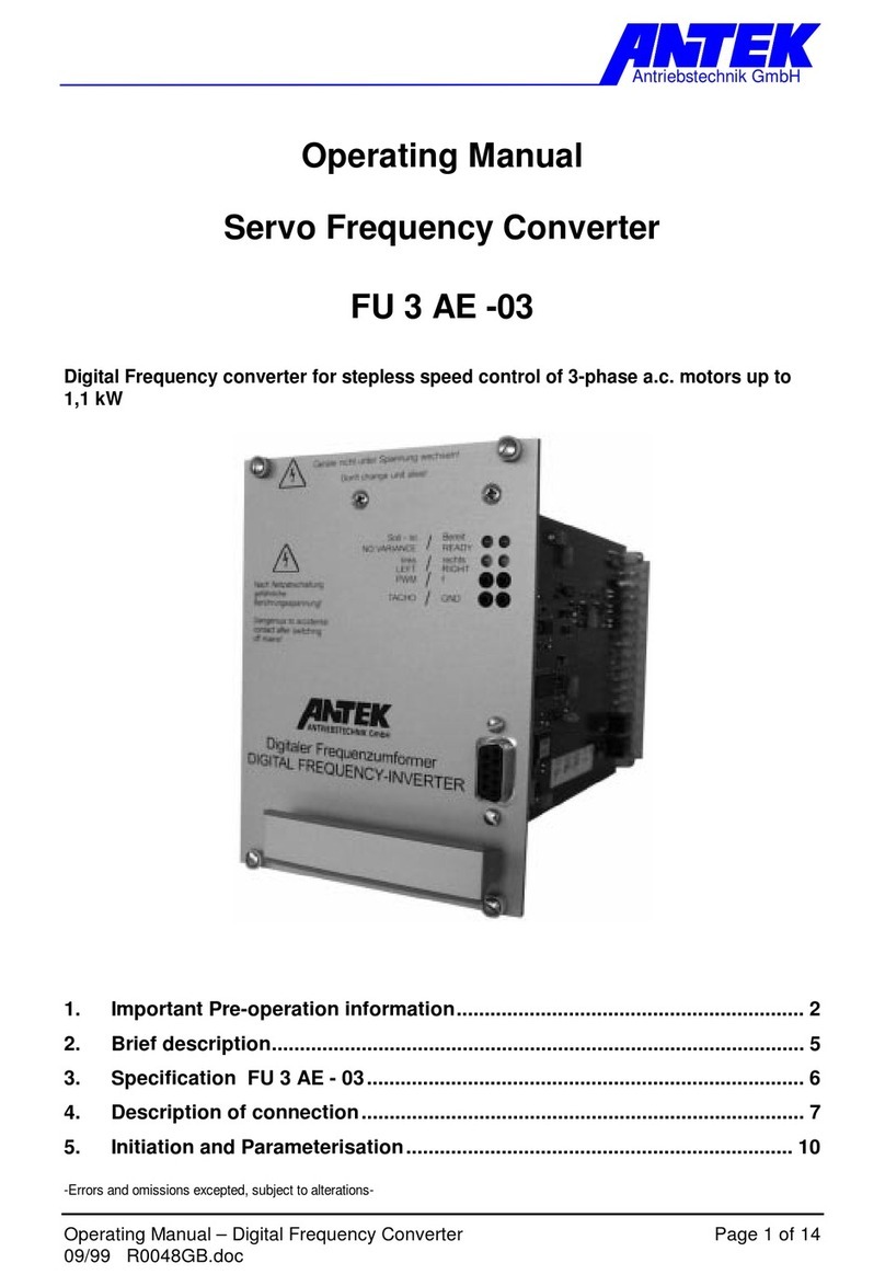
ANTEK FU3AM-03 User manual

Operating Manual
Frequency Converter FU3AM-03
Digital frequency inverter for stepless speed control
of asynchronous-three-phase a.c. motors

Operating Manual Frequency inverter
FU3AM-03
Document R0086EGB.doc
Version 05/13

Operating Manual FU3AM-03 Page 3 of 30
Contents:
Page
1. PREFACE AND GENERAL 5
1.1 BRIEF DESCRIPTION 5
1.2 ADVANTAGES: 5
1.3 EXTEND OF DELIVERY 5
1.4 DISCLAIMER 6
1.5 DEFINITIONS 6
2. SAFETY 7
2.1 OPERATING MANUAL 7
2.2 SYMBOLS 7
2.3 GENERAL SAFETY INFORMATION 7
2.4 OPERATOR RESPONSIBILITIES 8
2.5 PERSONNEL 8
2.6 INSTRUCTIONS ON UNPACKING,MOUNTING AND INSTALLATION 8
2.7 ELECTRICAL INSTALLATION 9
2.8 INFORMATION ON EMC 10
2.9 OPERATION OF THE FREQUENCY INVERTER 11
2.10 IMPORTANT INSTRUCTIONS ON PROTECTIVE EARTHING 11
2.11 IMPORTANT INSTRUCTIONS ON ROUTING OF WIRES 11
3. TECHNICAL DATA 12
3.1 TECHNICAL DATA FU3AM 12
3.2 LIMITING VALUES 13
3.3 REDUCTION OF POWER 13
3.4 DIMENSIONS 14
4. DESCRIPTION OF CONNECTION 15
4.1 ALL CONNECTIONS AT A GLANCE 15
4.2 CLAMP ASSEMBLY 16
CONNECTER DESCRIPTION 16
4.3 MOTOR CONNECTION PLUG X1 TO TOP OF DEVICE 17
4.4 MOTOR CONNECTION PLUG X2 TO BOTTOM OF DEVICE 17
4.5 CONNECTION MAINS PROTECTION X3 TO TOP OF DEVICE 17
4.6 CONTROL CONNECTION X4 18
4.7 DIGITAL 10-BIT SET VALUE PARALLEL INPUT X5 20
4.8 BRIDGE CONNECTOR FOR ONE-FAULT SAFETY 20
5. COMMISSIONING 21
5.1 SWITCH-ON SEQUENCE 21
5.2 DISPLAY 21
6. SERVICE INFORMATION 23

Page 4 of 30 Operating Manual FU3AM-03
6.1 SUMMARY OF PARAMETERS 23
6.2 CONFIGURATION UND USEFUL INFORMATION ON PARAMETERS 24
6.2.1 MODE 24
6.2.2 CHARACTERISTIC CURVE 25
6.2.3 SET POINT ADAPTATION,FIXED SET POINTS AND RAMPS 25
6.2.4 AUTOMATIC RESET 26
6.2.5 MOTOR TEMPERATURE MONITORING 26
6.2.6 FAN CONTROL 26
6.2.7 OPERATING HOURS COUNTER 26
6.2.8 OVERCURRENT CUT-OFF 26
7. FINDING AND ELIMINATING FAULTS 27
7.1 RESETTING FAULTS 27
7.2 POSSIBLE CAUSES OF FAULTS 27
8. OPERATING SOFTWARE 28
8.1 UNIDESK 28
8.2 SERIAL INTERFACE 28
9. REVISION INDEX 29
9.1 DOCUMENTATION 29
9.2 DEVISE 29
10. INDEX 30
-Errors and omissions excepted, subject to alterations-
ANTEK GmbH
Im Köchersgrund 1
71717 Beilstein
+49 7062 94060
+49 7062 940620
www.antek-online.de

Chapter 1: PREFACE AND GENERAL
Operating Manual FU3AM-03 Page 5 of 30
1. Preface and general
1.1 Brief description
Digital frequency inverter for stepless speed control of asynchronous three-phase AC motors
with numerous features, such as:
♦Wide range voltage input
♦Input-side mains filter already integrated
♦digital tachometer feedback (optional)
♦Temperature monitoring of output stage
♦Phase current monitoring of the motor winding
♦Input for any number of motor temperature sensors
♦Over- and under voltage monitoring of intermediate circuit
♦Levelling of intermediate circuit fluctuations
♦Act./Nom. monitoring of speed in controller mode
♦Aluminium profile housing for switch cabinet mounting
♦Plug-type connecting terminals (screw-in or spring-loaded push-in connector)
♦Integrated switching power supply
1.2 Advantages:
♦Compact and space-saving type
♦Excellent control properties over a broad control range
♦Versatile possibilities for set value specification:
♦Through analogue voltage
♦By means of programmable fixed speeds
♦Over digital control word
♦Reliable mains separation through integrated mains protection (with external activation,
with signalling contact)
♦Operation with industry standard motors
♦Sinusoidal excitation of the motor ensures that the latter runs true run even
at low speeds
♦Potential-free electronics
♦Overload-proof protection
♦Change direction of rotation by electronic system
♦Short launch times when using prefabricated and pre-inspected cable sets.
♦Service-friendly connection technology
♦Display shows every device status at a glance
♦Well-arranged device programming with ANTEK UniDesk
♦PC interface: standard-compliant RS 232 jack
♦Interference suppression class “A”
♦UL-CSA-Approbation
1.3 Extend of delivery
Frequency inverter for insertion in control cabinet . The frequency inverter has been tested
for correct functioning and continuous operation.

Chapter 1: PREFACE AND GENERAL
Page 6 of 30 Operating Manual FU3AM-03
1.4 Disclaimer
Liability
The information, data and instructions contained in this operating manual were up-to-date as
of the date of publication. No claims may be made in respect of inverters delivered previous-
ly on the basis of statements, illustrations/photos or descriptions contained in this operating
manual.
The process-specific instructions and circuit extracts contained in this manual are recom-
mendations. Their applicability to the task in hand must first be verified.
The firm ANTEK GmbH assumes no liability for the suitability of the processes described
and the suggested circuits contained herein.
No liability will be assumed for damages or malfunctions caused by:
♦disregarding this operating manual
♦unauthorized modifications made to the inverter
♦operator errors
♦improper working on and with the inverter
♦Operation of the inverter in mountings or connections, other than those described in this
manual.
Warranty
Warranty claims are to be made to the manufacturer as soon as a fault / defect is discov-
ered. The warranty will be voided by:
♦improper use of the inverter
♦improper working on and with the inverter
♦arbitrary modifications to the inverter
1.5 Definitions
Qualified Personnel
Qualified personnel are persons who, due to their training, experience and instructions, as
well as their knowledge of relevant standards and directives, safety-regulations, company
policies, and entitled by those responsible for the safety of the system, are justified to carry
out necessary tasks and recognize and avoid possible dangers.
(Definition for qualified employees per IEC 364)
Operator
An operator is any natural person or legal entity who operates the inverter, or in whose name
the frequency inverter is operated.

Chapter 2: SAFETY
Operating Manual FU3AM-03 Page 7 of 30
2. Safety
2.1 Operating Manual
This operating manual contains safety instructions for correct operation on and of the fre-
quency inverter, they are to be followed.
In addition to the general safety instructions contained in this chapter, the instructions con-
tained in the manual text must also be followed.
No claim is made that the safety instructions are complete. Please contact the manufacturer
in the event of questions or problems.
This manual must be available to all persons who work on or with the frequency inverter and
must remain in good, readable condition.
2.2 Symbols
In these instructions important explanations are highlighted with the following symbols:
Caution: this explanation indicates hazards which, under certain circumstances, may lead to
personal injury or material damage.
Attention required / Check: please pay special attention to the points described.
Information: provides you with further information relating to the product.
2.3 General Safety Information
The frequency inverter was state-of-the-art at the time of delivery and is considered princi-
pally safe to operate. The frequency inverter may present certain dangers to personnel, the
frequency inverter or other assets of the operator when:
♦non-qualified personnel work on or with the frequency inverter,
♦Operation of the inverter in other mountings or connections, other than described in this
manual.
♦the frequency inverter is improperly used.
Then exists danger for:
♦Persons
♦The frequency inverter
♦Other real value of the operator
The installations in which the frequency inverter is incorporated must be designed so that
they fulfil their functions when set up correctly and when used in accordance with the instruc-
tions in fault-free operation and do not cause any danger to persons. This also applies to the
interaction of the frequency inverter with the installation as a whole. In the case of applica-
tions in installations with technical safety requirements and with regard to installation, the
relevant laws and regulations must be complied with (e.g. EN 57100, EN 60204).
!

Chapter 2: SAFETY
Page 8 of 30 Operating Manual FU3AM-03
Take additional measures to limit consequences of error functions which can prove to be
dangerous for people:
♦other independent devices which safeguard against possible malfunction of the frequency
inverter.
♦electrical and non-electrical safety devices (locking or mechanical stops )
♦measures covering the system
Take appropriate measures to see that in case of malfunctioning of frequency inverter there
is no material damage.
When work is being carried out on live equipment, the relevant accident prevention regula-
tions must be obeyed.
For reasons of safety and of maintaining documented system data and functions, repairs to
the unit or its components are to be carried out only by the manufacturer.
No liability is accepted for inappropriate, incorrect manual or automatic setting of the param-
eters for the drive.
2.4 Operator Responsibilities
Responsibilities of the operator or safety officer:
♦to ensure adherence to all relevant directives, instructions and laws,
♦to ensure that only qualified personnel operate on or with the frequency inverter,
♦to ensure that the operating manual is available to all personnel.
♦to ensure that unqualified personnel do not work with the frequency inverter.
♦The operator is responsible for ensuring that the motor, the inverter and ancillary equip-
ment are installed and connected in accordance with the technical rules applicable in the
country in which installation is taking place and with other regulations which are applicable
regionally. In this context, special consideration must be given to cable.
2.5 Personnel
Only qualified personnel .may work on or with the inverter.
2.6 Instructions on unpacking, mounting and installation
Check for any transport damage after unpacking the control unit and before the initial start-
up.
Check that all plug-in and screwed connections are secure.
Minimum requirements for installation site:
♦The room should be as dust-free as possible (fit filters to
control cabinets which have floor fans).
♦The allowed ambient temperature and the relative air humidity must not to be exceed
(if required provide separate cooling).
♦The inverter causes power loss and heats up the environment. Ensure a sufficient dis-
tance from heat-sensitive equipment.
!
!

Chapter 2: SAFETY
Operating Manual FU3AM-03 Page 9 of 30
♦In the event of contaminated cooling air (dust, fluff, aggressive gases and grease), which
might adversely affect the functioning of the frequency inverter, adequate counter-
measures must be taken, e.g. separate air feed, installation of filters, regular cleaning,
etc.
♦The units are designed for mounting in suitable card racks .
♦The unit must be mounted vertically.
♦Ensure unimpeded access of cooling air and egress of discharged air. Clearances for
incoming and outgoing air must be complied with.
♦If the frequency inverter is continuously exposed to oscillation or vibration, vibration ab-
sorbers may be required.
2.7 Electrical Installation
♦The regulator contains components sensitive to electrostatics. Before installation and
service work in the terminal clamp area, the staff must free itself of electrostatic electricity.
The discharging can be achieved by touching a grounded metal surface beforehand.
♦To protect the power supply cables, the recommended cable protection fuse is required
♦The motor should be equipped with a temperature sensor . Evaluation can be performed
by the FU3AE-04 or a suitable analyser.
♦Control wiring and power cables must always be spatially separated from each other.
♦Set-value inputs must be shielded.
♦Conductor diameters for power supply and motor wiring must be at least 1,5 mm²!
♦Observe the current local safety regulations.
♦Use 60/75°C copper wire only
♦Tightening torque for field wiring terminals
♦Use in a pollution degree 2 environment
♦“Use Class 1 wire only” or equivalent
♦”Suitable for use on a circuit capable of delivering not more than 5kA rms symmetrical
amperes” for a max. voltage of 480 V.
Motor over temperature sensing according UL 508C is not provided by the drive or
equivalent.
!

Chapter 2: SAFETY
Page 10 of 30 Operating Manual FU3AM-03
2.8 Information on EMC
In order to warranty electromagnetic compatibility (EMC) in your switch cabinets in an elec-
trically raw environment, the following EMC rules are to be observed during construction and
set-up:
♦All metallic parts of the switch cabinet are to be connected flatly and in a well-conducting
manner (not lacquer on lacquer!). If necessary, use contact or scraper wafers. The cabi-
net door is to be connected with as short a circuit as possible via the metal powder tapes
(upper, middle, lower).
♦Signal lines and power cables are to be laid separated from each other in order to avoid
coupling intervals. Minimum distance: 20 cm:
♦Signal lines should be led to the cabinet from only one level, if possible.
Unshielded lines from the same electrical circuit (outgoing and return circuit) are to be
transposed, if possible.
♦Contactors, relays and magnetic valves in the switch cabinet, if necessary in the adjacent
cabinets, are to be wired with suppressor combinations, e.g. with RC elements, varistors
or diodes.
♦The braiding from signal lines are to be laid two-way (source and target), large-area and
well-conducting to a ground1. In case of poor potential equalization between shielded
connections, an additional balancing network of at least 10 mm² must be laid parallel to
the braiding to reduce the current.
♦Wiring is not to be laid freely in the cabinet, but should rather lead as tightly as possible to
the cabinet frame or to installation plates. This also applies to reserve cables. At least one
end of them must be grounded, but preferably both (additional shield effect).
♦Unnecessary wire lengths are to be avoided. Coupling capacities and coupling induct-
ance’s are thereby kept small.
♦The braiding from leads, such as resolver or incremental tachometer cables, must be laid
to the frame grounding. Approximately 2 cm of the insulation is to be removed in the area
where the cable is to be led into the frame in order to expose the braided cable. The
braided cable may not be damaged while removing the insulation. The cable is to be led
at the position where the insulation has been removed by grounded terminals or taut sup-
ports.
cable
clamping yoke
1Generally all metallic conducting parts which can be connected to a protective conductor,
such as cabinet frames, motor frames, foundation grounding, etc. are designated as a
ground.

Chapter 2: SAFETY
Operating Manual FU3AM-03 Page 11 of 30
2.9 Operation of the frequency inverter
Operate the frequency inverter only if it is in perfect condition. The permissible conditions of
use and output limits must be complied with.
Retrofitting, modifications or conversions of the frequency inverter are forbidden. In all such
cases, the manufacturer must be consulted.
The frequency inverter is an item of equipment for use in industrial installations. During op-
eration, these items of equipment have dangerous, live components. Consequently, during
operation all covers must be fitted to the drive controller, in order to ensure full protection
from contact with it.
The modules include electro statically sensitive CMOS und MOS components. Caution must
be exercised in respect of electrostatic charges.
2.10 Important instructions on protective earthing
Because of the loss currents of the essential mains filter (>3.5 mA) via the protective earth-
ing conductor (PE), according to DIN VDE 0160 the cross-sectional area of the lead-in wire
of the protective earth wire to the switch cabinet must be at least 10 mm² Cu, or a second
protective earth conductor must be laid electrically in parallel.
In the case of higher installed loads, the minimum cross-sectional area of the protective
earth conductor must be in a corresponding relation to the cross-section of the outer conduc-
tors (see DIN 57100 Part 540).
The loss currents of the filter may be as high as 100 mA. Operation with FI earth leakage
circuit breakers is therefore not possible.
2.11 Important instructions on routing of wires
Control lines and power cables must always be routed separately with a gap between them.
Tacho inputs, set point and analogue control inputs must be laid using shielded cables.
!
!

Chapter 3: TECHNICAL DATA
Page 12 of 30 Operating Manual FU3AM-03
3. Technical data
3.1 Technical Data FU3AM
Type FU3AM
Input voltage range Umains:
Input frequency:
VAC
Hz
3x 380 -10% ... 480 +10%;
45 ... 66
Nominal input current I
N
: AAC 3x 3
Peak input current: AAC 3x 5
Connect load: kVA 2,1
Fuse protection extern 1: A Motor protecting switch
(e.g. ABB MS116-4)
24 VDC supply of main contactor: VDC 24 ±10%
Nominal output voltage U
a
0 ... U
e
Nominal output current I
a
: AAC 3x 3
Peak output current: I
max
AAC 3x 5
Output frequency f
out
: Hz 0 ... 160
Nominal output power S: kVA 2,1
min. output inductance L: mH 2
Regulating range with pulse generator
(number of gradations > 100)
1:100
Output stage clock frequency: kHz 4, 8, resp. 16
Installation: vertical
Ambient temperature: °C/(°F)
5 ... 40/(41…104)
Atmospheric humidity % max. 90 non-condensing!
Connecting terminal:
Input- and motor connection:
Mains contactor and control terminal:
Parameters:
Phoenix Contact PC4HV-7,62
Wieland 8513BFK
SUB-D 9-pole (Edge socket con-
nector)
Protection class: IP 20
Dimensions (WxHxD): mm 70x235x170
Standards and regulations:
Spark disturbance
Approbation / UL-File
DIN 57110b
EN 60204
EN 55011b Class A
UL-CSA (E181898)
connection °C use 60/75°C copper wire only
Tightening torque for field wiring terminals
Use in a Pollution degree 2 environment
“Use Class 1 wire only” or equivalent
”Suitable for use on a circuit capable of
delivering not more than 5kA rms symmet-
rical amperes” for a max. voltage of 480 V.
Motor over temperature sensing according UL 508C is not provided by
the drive or equivalent.
Technical specifications are based on 400 VAC mains input voltage, cycle frequency 4 kHz, 1000 m
installation height, unless otherwise stated.
1Note:
Here is no fuse in the unit for the mains supply. It is essential to provide motor protecting
switch, since the unit is not protected otherwise.

Chapter 3: TECHNICAL DATA
Operating Manual FU3AM-03 Page 13 of 30
3.2 Limiting values
UZK (Intermediate circuit voltage) max. ~ 790 VDC
min. ~ 400 VDC
Heat sink temperature 80°C/(176°F)
Air temperature 70°C/(158°F)
Power loss diagram:
3.3 Reduction of Power
At operating altitudes of more than 1000 m above sea level or ambient temperatures over
40°C/104°F, the output of the converters is to be reduced to correspond to the following fig-
ures.
Reduction of Power in Temperature
Increase
Reduction of Power at Operating Altitudes of more than
1000m
10 00 2000 3000 4000 5000
Temperature in °C/°F
Operating Altidude in m
Output
Power
in %
Output
Power
in %
100
80
60
40
20
40/104 50/102 60/140
7
0/158
100
80
60
40
20
Power loss
(W)
100
20
Output voltage (A)
0
3
4kHz
8kHz
16kHz
Output stage clock frequency

Chapter 3: TECHNICAL DATA
Page 14 of 30 Operating Manual FU3AM-03
3.4 Dimensions
170
FU3AM
70
235
220
5,5
Socket screw M5x20 with
washer and spring ring
captive
8

Chapter 4: DESCRIPTION OF CONNECTION
Operating Manual FU3AM-03 Page 15 of 30
4. Description of connection
4.1 All connections at a glance

Chapter 4: DESCRIPTION OF CONNECTION
Page 16 of 30 Operating Manual FU3AM-03
4.2 Clamp assembly
(top side )
X1
X3
4
3
2
1
4
1
(bottom side)
X2
X4
X6
1
2
3
4
15
1
6
1
9
1
X5
Connecter description
X1: Mains connection (see sec: 4.3)
X2: Motor connection (see sec.: 4.4)
X3: Mains contactor (see sec.: 4.5)
X4: Control connection (see sec.: 4.6)
X5: Set point parallel input (see sec.: 4.7)
X6: Strapping plug (see sec.: 4.8)

Chapter 4: DESCRIPTION OF CONNECTION
Operating Manual FU3AM-03 Page 17 of 30
4.3 Motor connection plug X1 to top of device
X1
4
3
2
1
X1-1 PE
X1-2 L1
X1-3 L2 input voltage
X1-4 L3
Cable cross section: 1,5 ... 4mm² (AWG 15 ... 10)
Tightening torque: 0,6Nm
4.4 Motor connection plug X2 to bottom of device
X2
1
2
3
4
X2-1 PE
X2-2 U Motor connection
X2-3 V Attention! motor line must always be shielded
X2-4 W Lay screen over a wide area on both sides to PE
Attention! do not connect capacitive load. Uncouple motor line through
ferrite ring.
Cable cross section: 1,5 ... 4mm² (AWG 15 ... 10)
Tightening torque: 0,6Nm
4.5 Connection mains protection X3 to top of de-
vice
X3
4
1
X3-1 Auxiliary contact Signal contact (N.O.)
X3-2 Auxiliary contact Signal contact (N.O.)
X3-3 0V Mains protection coil
X3-4 +VDC Mains protection coil (excitation volt-
age external)
Cable cross section: 0.4 … 1.5 mm2 (AWG 21 … 16) single/fine strand
8mm
!

Chapter 4: DESCRIPTION OF CONNECTION
Page 18 of 30 Operating Manual FU3AM-03
4.6 Control connection X4
X4
15
1
X4-1 GND
X4-2 Thermo
Input for motor-thermal contact
Any thermo-contact (N.C. or N.O.) or thermo-sensor (NTC or PTC) against GND
X4-5 GND
X4-6 Soll
Analogue set value (reference GND)
0 … 10VDC input resistance = 100 kOhm
X4-3 GND
X4-4 Tacho
Input f. impulse device tacho (2-wire technology)
Special impulse device for ANTEK drives

Chapter 4: DESCRIPTION OF CONNECTION
Operating Manual FU3AM-03 Page 19 of 30
X4-7 Set-Actual
OK
X4-8 Ready
X4-9 COM+
Signalling contact (potential-free): set speed achieved
(only in controller mode)
Ready signaling contact (potential-free))
Reference point for X4-8 and X4-7 (potential-free)
Loading capacity of the signaling outputs: 0.2A, 35VDC or 25VAC
X4-10 GND
X4-11 N2
X4-12 N1
Reference mass for X4-11 ... X4-15
Fixed speed N2 or digital set value, Bit 1
Fixed speed N1 or digital set value, Bit 0
With parameter “source set value” -> “analogue”: N1, N2
With parameter “source set value” -> “digital”: SW_0, SW_1
Fixed set values:
With the input signals fixed speed #1 and fixed speed #2, 3 fixed speeds through
binary coding or the analogue set value specification can be selected.
LOGIC DIAGRAM : Fixed speed N1
Fixed speed N2
Analogue set value LOW LOW
Fixed set value n1 HIGH LOW
Fixed set value n2 LOW HIGH
Fixed set value n3 HIGH HIGH
For parameterisation of the fixed set values, see Section.: 6.2.3
Low = 0 ... +2VDC or open
High = +15 ... 30 VDC
X4-13 L/R
X4-14 RF
X4-15 Reset
High: counter-clockwise rotation, Low: clockwise rotation
Controller enable
Low-High-Flank = fault reset
Low = 0 ... +2VDC or open
High = +15 ... 30 VDC
Cable cross section: 0.4 … 1.5 mm2 (AWG 21 … 16) single/fine strand
8mm

Chapter 4: DESCRIPTION OF CONNECTION
Page 20 of 30 Operating Manual FU3AM-03
4.7 Digital 10-bit set value parallel input X5
9
1
X5
X5-1 GND Reference potential for
digital set value inputs
X5-2 SW_2 digital set point, Bit 2
X5-3 SW_3 digital set point, Bit 3
X5-4 SW_4 digital set point, Bit 4
X5-5 SW_5 digital set point, Bit 5
X5-6 SW_6 digital set point, Bit 6
X5-7 SW_7 digital set point, Bit 7
X5-8 SW_8 digital set point, Bit 8
X5-9 SW_9 digital set point, Bit 9
Note: For compatibility reasons the inputs SW_0 and SW_1 are to be found on X4-12
and X4-11. If only 8-bits are to be used, SW_0 and SW_1 must be on Low (and/or open).
Low = 0 ... +2VDC or open
High = +15 ... 30 VDC
Cable cross section: 0.4 … 1.5 mm² (AWG 21 … 16) single/fine strand
8mm
4.8 Bridge connector for one-fault safety
Bridge connector for wiring of the one-fault safety
Table of contents
Other ANTEK Media Converter manuals
Popular Media Converter manuals by other brands

SightLine
SightLine 3000-OEM quick start guide

PI Manufacturing
PI Manufacturing BALUN-100-2-500 user manual

Lantronix
Lantronix 4120 Series user guide

ADF Web
ADF Web HD67837-B2 user manual

Linear Technology
Linear Technology LTC3455EUF-1 quick start guide

almando
almando Multiplay Surround Decoder Installation and operating instructions