Operating Manual – Digital Frequency Converter Page 6 of 14
09/99 R0048GB.doc
Antriebstechnik GmbH
123
20
40
60
0
0
Pv[W]
Ia[A]
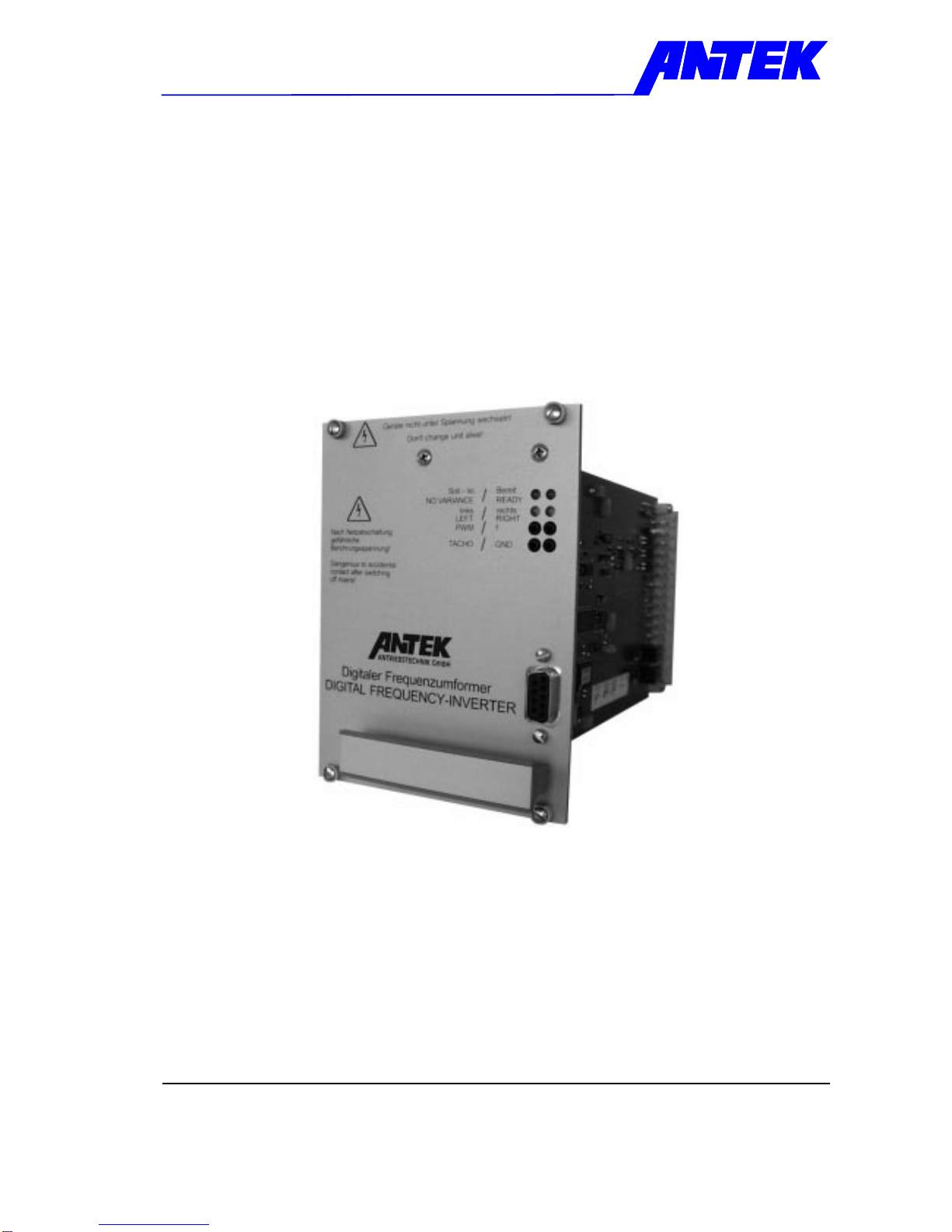
3. Specification FU 3 AE - 03
for application compliant with UL (UL 508) and CSA regulations
Input voltage: UNetz 3x 400 VAC -10% ... 480 VAC +6%; 50/60 Hz
Rated input current: IN3x 3 AAC
Peak input current: 3x 5 AAC
Connection power: 2,1 kVA
Fuse external: 3x 10 A Z-Characteristic, e.g.. ABB S283-Z10
24 VDC supply external: 24 VDC ±20% current consumption ca. 0,4 A
fuse 1 A intern
Nominal output voltage: Ua0 ... Ue
Nominal output current Ia3x 3 AAC
Peak output current: 3x 5 AAC
Output frequency: fout 0 ... 160 Hz
Frequency resolution: 200 Steps relevant to output frequency
Nominal output power: S 2,1 kVA
min. output inductivity:: L 2 mH
Control range pulse generator 1:100
(Graduations > 100)
Efficiency at nominal load: ca. 95%
Power loss at no-load: ca. 20 W
Power loss nominal load: ca. 60 W
Clock frequency of output
transformer:: ca. 3,9 kHz
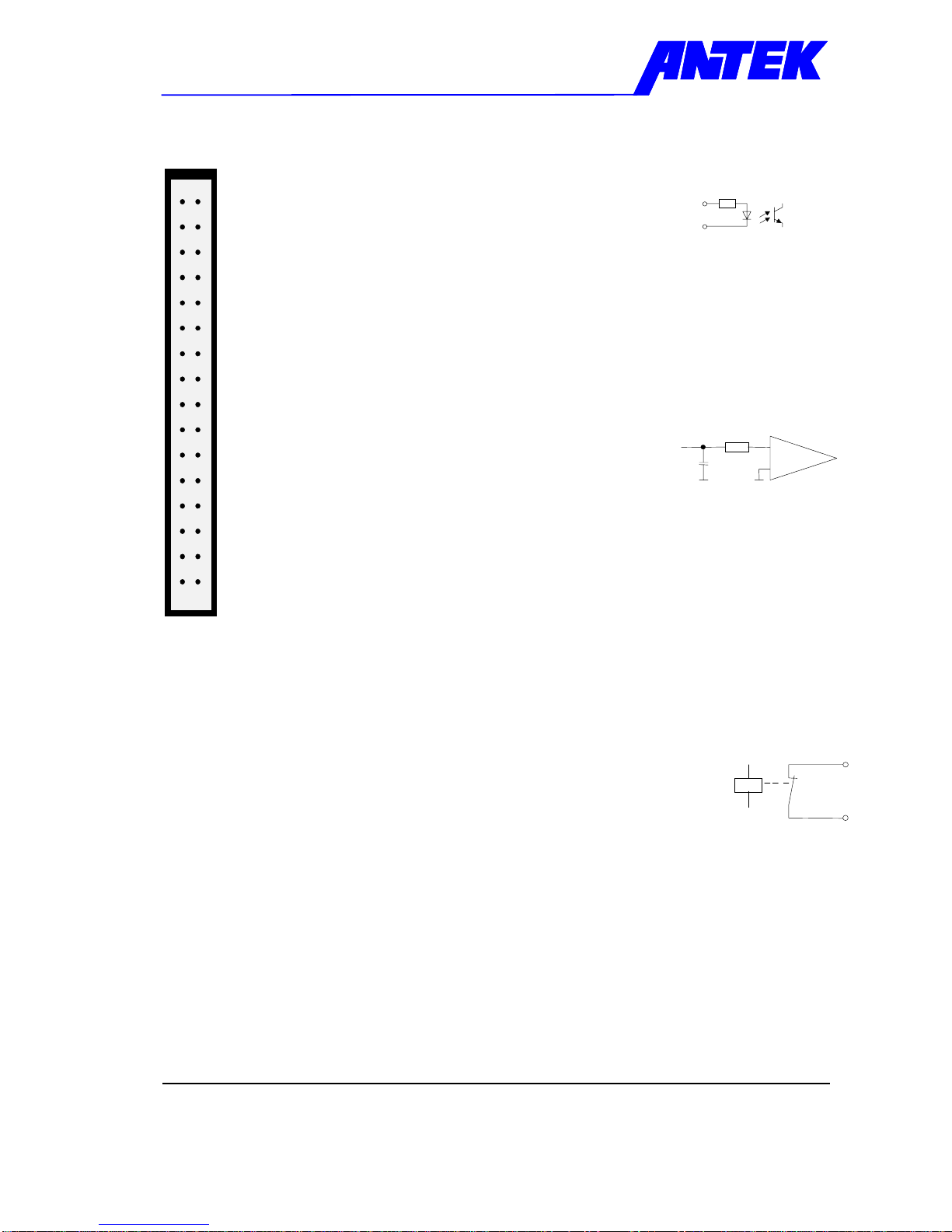
Digital Control inputs: Reglerfreigabe, Reset-Fault
Outputs: Potential-free signal output for
actual / nominal monitoring, ready
Max. load: 35 VDC; 0,2 A
Set point input: 0 ... 10VDC
Actual r.p.m. feedback: Pulse generator 24VDC
Installation: card rack, cooling plate vertical
Ambient temperature: 5 ... 40 °C
Cooling: Ducted cooling 60 m³/h
Connection: Power plug E-L12 form H11
Card connector GDS-AC32 form C
SUB-D 9 pole (female)
Degree of protection IP 00
Geometry: 19“ plug-in module, 3 HE x 19 TE, depth ca. 190 mm
Standards and instructions: DIN 57110b
EN 60204
EN 55011b only with main filter A395
UL-Approbation File E181898
Note:
There is no fuse in the unit for the main supply. Always fit an automatic circuit-breaker with 3 x 10 A Z
characteristic, otherwise the unit is not protect.
Technical Specifications applicable by 400 VAC mains input voltage