ANTTI Vacboost M13 User manual

Installation and
Operating Instructions
03-2019
ANTTI GRAIN DRYER
Antti Mobile Dryer
Vacboost M13
408111 (en)
ANTTI-TEOLLISUUS OY
Koskentie 89
FI-25340 Kanunki, Salo
Tel. +358 2 774 4700
E-mail: antti@antti-teollisuus.
www.antti-teollisuus.

ANTTI MOBILE DRYER VACBOOST M13 ............................................................................................................ 4
SELECTING LOCATION FOR THE DRYER.......................................................................................................... 4
FOUNDATION ........................................................................................................................................................4
THE SPACE REQUIRED FOR THE INSTALLATION............................................................................................. 5
PRESENTATION OF THE MACHINE .................................................................................................................... 5
SAFETY..................................................................................................................................................................6
Follow the local instructions for occupational safety............................................................................................... 6
INSTALLATION OF THE ANTTI VACBOOST MOBILE DRYER ............................................................................ 6
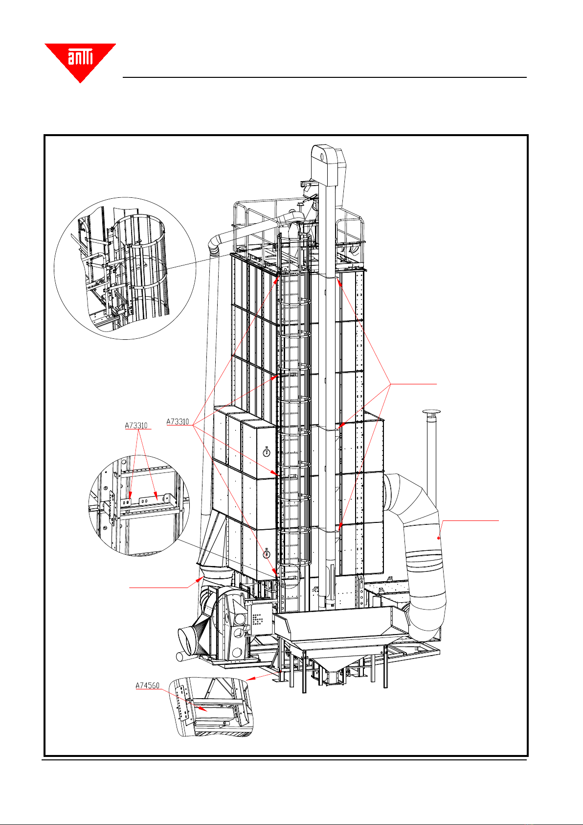
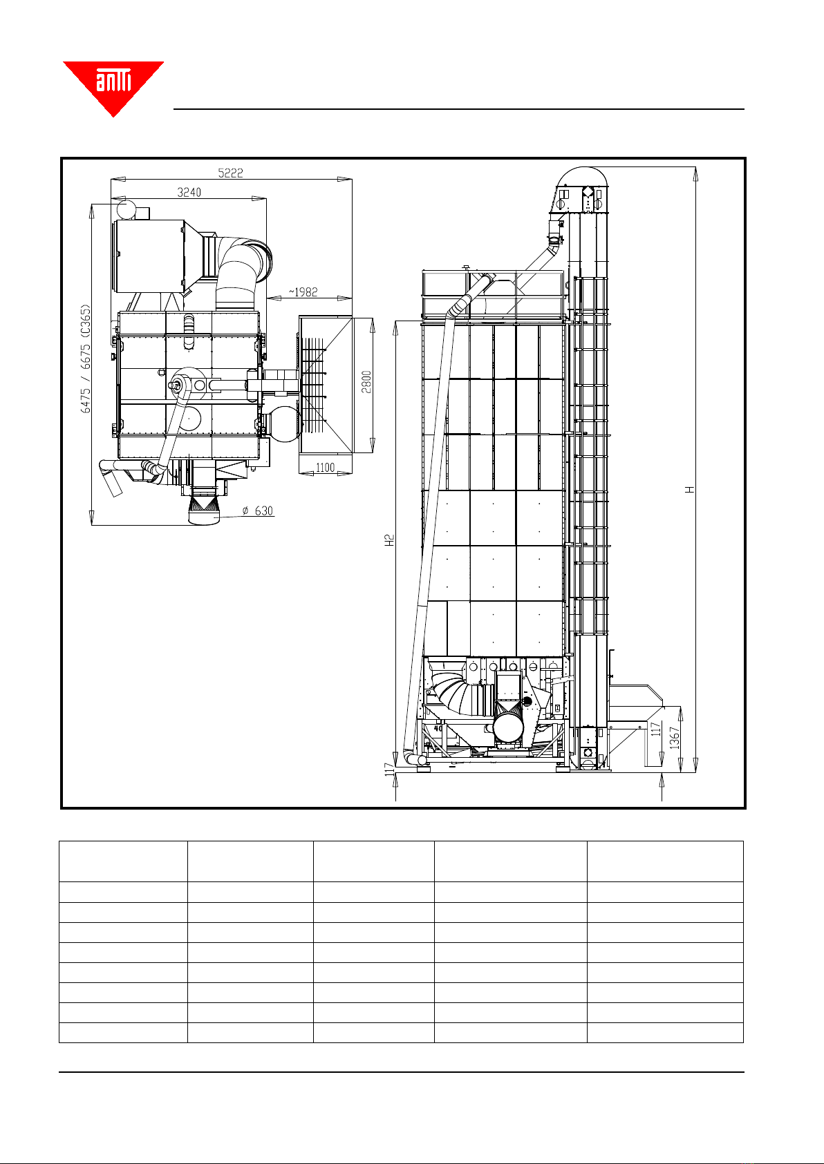
Principle drawings of dierent dryer types with accessories .................................................................................. 8
Base with frame....................................................................................................................................................26
Sections, air channel ends ................................................................................................................................... 26
Top tanks and cover with handrails ...................................................................................................................... 26
Installing the upper limit sensor............................................................................................................................ 27
(Capacitive, adjustable)........................................................................................................................................27
Installing the elevator............................................................................................................................................27
Large bolt-assembled hopper .............................................................................................................................. 27
The intake pit with Skandia conveyor................................................................................................................... 27
Wire control of the 3-way divider and the circulation pipes .................................................................................. 28
Installing the blower stand....................................................................................................................................34
Fuel pipes.............................................................................................................................................................36
Installing the debris piping for the pre-cleaner......................................................................................................36
Electric installations..............................................................................................................................................37
1. Installation ........................................................................................................................................................39
1.1 Installing the LTM thermostat ......................................................................................................................... 39
1.2 Installing the re thermostat ........................................................................................................................... 40
1.3 Installing the temperature sensors ................................................................................................................. 41
1.4 Installing the upper limit sensor...................................................................................................................... 41
2. STARTING UP................................................................................................................................................. 42
2.1 Elevator .......................................................................................................................................................... 42
2.2 Pre-cleaner.....................................................................................................................................................42
2.3 Feeder ........................................................................................................................................................... 43
2.4 Blower.............................................................................................................................................................43
2.5 Burner.............................................................................................................................................................43
2.6 LTM thermostat............................................................................................................................................... 43
3. Functions of the control centre ........................................................................................................................ 44
3.1 Switches and buttons ..................................................................................................................................... 44
3.1.1 Operation switch..........................................................................................................................................44
3.1.2 Operating switch for the elevator................................................................................................................. 45
3.1.3 Operating switches for other appliances ..................................................................................................... 45
3.1.4 Bypass button..............................................................................................................................................46
3.1.5 Start button..................................................................................................................................................46
3.2 Operating hour counter .................................................................................................................................. 46
3. 3 Outlet air and drying temperature thermostats.............................................................................................. 46
3. 4 Cooling timer ................................................................................................................................................. 47
3.4.1 Display.........................................................................................................................................................47
3.4.2 Setting the cooling time ............................................................................................................................... 47
3.4.3 Interrupting the cooling................................................................................................................................47
3.5 Frequency converter controlled feeder........................................................................................................... 48
3.6 Signal lights .................................................................................................................................................... 49
CONTENTS
Translation of original

Antti-Teollisuus Oy 3 408111 03-2019
Vacboost M13
3.6.1 Signal lights of the appliances..................................................................................................................... 49
3.6.2 Cooling ........................................................................................................................................................49
3.6.3 Signal light "drying nished" ........................................................................................................................ 49
3.6.4 Level guard..................................................................................................................................................49
3.6.5 Circulation failure.........................................................................................................................................49
3.6.6 Overheating alarm.......................................................................................................................................50
3.6.7 Burner failure...............................................................................................................................................50
3.7 Motor protection switches............................................................................................................................... 50
3.8 Circuit breakers .............................................................................................................................................. 51
4. Operation......................................................................................................................................................... 51
4.1 Filling ..............................................................................................................................................................51
4.2 Drying and cooling.......................................................................................................................................... 51
4.2.1 Drying the rst batch....................................................................................................................................51
4.2.2 Starting the drying process.......................................................................................................................... 52
4. 3 Emptying........................................................................................................................................................52
5. Malfunctions .................................................................................................................................................... 52
THERMAL INSULATION ......................................................................................................................................53
OPERATION INSTRUCTIONS FOR THE DRYER MACHINERY (detailed instructions)..................................... 53
Initial adjustment and checking of the dryer ......................................................................................................... 53
Drying ...................................................................................................................................................................53
Cooling .................................................................................................................................................................54
DRYING TECHNICS ............................................................................................................................................55
MAINTENANCE AND OPERATING ADJUSTMENTS.......................................................................................... 56
ECONOMICAL DRYING.......................................................................................................................................57
POSSIBLE MALFUNCTIONS .............................................................................................................................. 60
SERVICE AND WINTER MAINTENANCE .......................................................................................................... 60
GUARANTEE .......................................................................................................................................................61
CLADDING OF THE WAGON .............................................................................................................................. 62
Cladding ...............................................................................................................................................................62
Cutting the cladding plates ...................................................................................................................................63
Cladding strips......................................................................................................................................................65
Installing the attachment strips of the cladding.....................................................................................................66
EU Declaration of Conformity............................................................................................................................... 73

Antti-Teollisuus Oy 4 408111 03-2019
Vacboost M13
ANTTI MOBILE DRYER VACBOOST M13
Read the Installation and Instruction Manual carefully before installing the machine and putting it into operation.
SELECTING LOCATION FOR THE DRYER
Locate the grain dryer as a part of the farm's centre of operations, taking into account possible trac, noise and
dust problems. Construct the roads in a manner enabling them to be tracked with a full trailer round the year.
If possible, locate the heater on the facade side of the building. When selecting location for the heater, observe
in particular that it requires large amounts of clean air. The suction opening of the heater must be located as far
from the outlet air pipes as possible, on the other side of the building. If you have doubts concerning the location,
negotiate in advance with the local building and road authorities, and the re chief.
The distance from the grain dryer to the land of the neighbour shall be at minimum 15 m, to the neighbouring
building 20 m, to your own residential building15 m, and to an outbuilding 12 m. (The minimum distance to your
own buildings may vary from municipality to municipality, depending on how the new regulations are being locally
interpreted). For dryers of category P2, the required distances may be shorter. Under certain conditions, a package
dryer may fall into category P2. Consult the local re chief or building supervisor for detailed instructions.
FOUNDATION
GROUND PRESSURE
When selecting suitable founding method for your dryer, apply the following base values for dierent soil types:
Moraine 0,4 – 0,8 MN/m2
Gravel 0,2 – 0,6 MN/m2
Sand 0,15 – 0,5 MN/m2
Fine sand 0,1 – 0,4 MN/m2
Clay and ne silt:
- soft (easy to work) 0,025 MN/m2
- tough (hard to work) 0,050 MN/m2
- solid (extremely hard to work) 0,1 MN/m2
If you consider that the load-bearing capacity of the soil is dicult to determine, assign a specialist or order a ground
survey. It is often a good idea to establish the form of the rock by means of a ground survey or a test excavation.
Typically, the ground pressure caused by a dryer is 0.5–2.0 kg/cm2when the foundation is of raft type.

Antti-Teollisuus Oy 5 408111 03-2019
Vacboost M13
THE SPACE REQUIRED FOR THE INSTALLATION
The minimum requirement is that the foundation drawings are being followed.
In addition, you must take into account the space required for the installation, and the load-bearing capacity of the
soil under the mobile crane.
The goods to be transported can be over 3 metres wide and fairly long. Therefore, the access to the foundation of
the dryer must be unobstructed, and sucient space must be reserved for turning the vehicles.
For the erection of the dryer, the mobile crane must be provided with unobstructed access near the installation
site and a suciently sturdy standing base. There must not be any aerial electric or telephone lines at the erection
site, within the reach of the mobile crane.
Instruction manual for erecting and operating the machine
This manual is intended for professional farmers. The use of the machine requires normal skills and general
knowledge of farming.
Grain dryer type
This manual deals with installation and use of ANTTI VACBOOST MOBILE DRYER M13.
PRESENTATION OF THE MACHINE
- Grain dryers are intended for drying of grain and seeds.
- The drying process comprises four phases:
1. During the lling phase, the elevator transfers the grain from the lling hopper of the dryer into the dryer.
2. During the drying phase, the grain circulates inside the dryer, and simultaneously, hot air is being sucked
through the grain layers.
3. During the cooling phase, the grain is being circulated inside the dryer, and cold outside air is being sucked
through the grain layers.
4. The ready-dried and cooled material is transferred by means of an elevator to the storage or to be loaded.
The dryer is delivered as pre-assembled units, and the nal assembly takes place at the installation site.

Antti-Teollisuus Oy 6 408111 03-2019
Vacboost M13
- The pedestal of the dryer comprises the dryer base and the feeder. The drying sections are installed on top
of the base.
- The drying unit comprises drying sections with triangular air ducts. The top tanks are stacked on top of the
drying unit.
- Dryer type: The ANTTI VACBOOST 3W with seven feeder blades.
- The volume of the dryer depends on the number of the sections and the top tanks, being installed one on top
the other.
- In addition to the main parts itemised above, the delivery also includes a number of smaller parts, the instal-
lation of which is described more in detail later in these instructions.
In mobile dryers, the most signicant source of noise is the blower/blowers.
NOTE! Always use hearing protectors near the blower units, while the suction fans are in operation.
- Measuring point at a distance of 1 m from the suction opening of the blower unit L Aeq 92 dB
- Measuring point at a distance of 10m from the suction opening of the blower unit L Aeq 75 dB
SAFETY
The dryer base has moving feeder parts that can cause an injury, if all the cover plates and hatches are
not properly closed, while the machine is in operation!
NOTE!
Before opening or closing the bottom troughs, ensure that the inspection and cleaning hatches in the
dryer base are closed.
Follow the local instructions for occupational safety.
INSTALLATION OF THE ANTTI VACBOOST MOBILE DRYER
Refer to the erecting instructions 408076 for the dryer for installation of the sections and the other basic components.
These instructions deal with the installation of the mobile dryer's model-specic components.
The installation work of the dryer requires precision. The work must be carried out on various levels, even at high
elevations. Therefore, in addition to good installation skills, the work requires proper scaolding/use of aerial work
platforms and observation of all the safety issues. Especially, the dryer base and the sections are heavy. Lifting
them requires suciently powerful machinery.
Pre-connected wiring is used for installations in the electric centre. Before starting the use, make sure that all the
electric appliances are in order!

Antti-Teollisuus Oy 7 408111 03-2019
Vacboost M13
Weight of the dryer's components:
Base with heater and blower ~2400-2700 kg
Section (with two air channel ends) ~1400-2000 kg
Top tank ~300 kg
Top tank with cover, handrails and pre-cleaner ~700 kg
Elevator ~450-590 kg
Please observe, when lifting the heavy components of the dryer:
- use all the lifting lugs on the components
- use the lifting lugs and a bracing when lifting the ready-assembled top tank
- ensure that the lifting hooks stay in position in the lugs, and that the crane being used is suciently powerful
- never go under or too near the components to be lifted
- the crane must be able to lower the component to be lifted slowly and precisely into position
- reserve 3–5 tools that can be used as guide pins such as, for example, pin punches of 5–8 mm in diameter
Provide all the seams with sealing band.
Note! If you wish to stack several sections, and lift them on top of the base in one go, use the separate lifting lugs
(501010). Refer to the erecting instructions 408076 for detailed instructions. Attach the lifting lug by eight M8
bolts. Brace the lugs by xing battens of 50x100 by the two holes to support the lugs so that the section end will
not bend. Use the same lugs for lifting the top tanks.
The dryer can be assembled from larger sub-assemblies. All the drying sections and the top tanks can be lifted
into place using the robust lugs on the top. An example: the top tanks and the top tank cover with handrails can
be assembled while the section is still on the ground. Tighten all the bolts – use M10 bolts for xing the vertical
supports. Lift this large sub-assembly onto the top of the base.
NOTE!
The total weight of the sub-assembly is several tonnes, so a heavy crane is required. Verify the load-bearing ca-
pacity of the soil, before the lifting.

Antti-Teollisuus Oy 8 408111 03-2019
Vacboost M13
Principle drawings of dierent dryer types with accessories
Elevator support
PTC sensor
Fire thermostat
PTC sensor
LTM thermostat
Principle drawing of the assembly (C365)

Antti-Teollisuus Oy 9 408111 03-2019
Vacboost M13
Mittakuva Antti Vacboost ilman tekstejä
M10 eye-bolts as
guides
Distributor wires
Cable lad-
ders
Flue pipe
support
Antti Vacboost
Model H H2 Elevator Elevator
mm mm t/h kW
C255 10100 6990 45 3
C320 11100 8150 50 4
C365 12100 9300 50 4

Antti-Teollisuus Oy 10 408111 03-2019
Vacboost M13
Mittakuva Antti Vacboost E ja ES
Antti Vacboost E/ES
Model H H2 Elevator Elevator
mm mm t/h kW
C255E 10700 6990 60 4
C320E 11700 8150 60 4
C365E 12700 9300 60 4
C410E 13700 10500 100 7,5
C255ES 13700 6990 60 4
C320ES 15700 8150 60 5,5
C365ES 16700 9300 60 5,5

Antti-Teollisuus Oy 11 408111 03-2019
Vacboost M13
C365E A1500 kW 1x15 kW_Mitttakuva
C 365E A1500 kW 1x15 kW

Antti-Teollisuus Oy 12 408111 03-2019
Vacboost M13
C410E 700 kW 2x7,5 kW_Mitttakuva
C 410E 700 kW 2x7,5 kW

Antti-Teollisuus Oy 13 408111 03-2019
Vacboost M13
C410E 1000 kW 2x15 kW_Mitttakuva
C 410E 1000 kW 2x15 kW

Antti-Teollisuus Oy 14 408111 03-2019
Vacboost M13
C410E A1500 kW 2x15 kW_Mitttakuva
C 410E A1500 kW 2x15 kW

Antti-Teollisuus Oy 15 408111 03-2019
Vacboost M13
Mittakuva Antti Vacboost EH ja EHS
Antti Vacboost EH/EHS
Model H H2 Elevator Elevator
mm mm t/h kW
C255EH 12700 6990 60 4
C320EH 13700 8150 80 5,5
C365EH 14700 9300 80 5,5
C255EHS 16700 6990 60 5,5
C320EHS 17700 8150 80 7,5
C365EHS 18700 9300 80 7,5

Antti-Teollisuus Oy 16 408111 03-2019
Vacboost M13
Kaatoallas kuljettimella_Mittakuva
Intake pit with conveyor;
see the instruction 408115 for more detailed dimensioning

Antti-Teollisuus Oy 17 408111 03-2019
Vacboost M13
C 255
C 255_malli

Antti-Teollisuus Oy 18 408111 03-2019
Vacboost M13
C 320
C 320_malli

Antti-Teollisuus Oy 19 408111 03-2019
Vacboost M13
C 365
C 365_malli

Antti-Teollisuus Oy 20 408111 03-2019
Vacboost M13
C365 E-A1500_3D
C365 E A1500
Table of contents