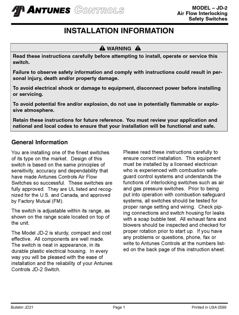
Antunes Controls G Service manual

WARNING
Read these instructions carefully before attempting to install, operate or service this
switch.
Failure to observe safety information and comply with instructions could result in
personal injury, death and/or property damage.
To avoid electrical shock or damage to equipment, disconnect power before installing
or servicing.
To avoid potential fire and/or explosion, do not use in potentially flammable or
explosive atmosphere.
Retain these instructions for future reference. You must review your application and
national and local codes to ensure that your installation will be functional and safe.
GGI 1010810019 Page 1 Printed in USA 0700
MODEL - G
Gas Pressure Switches
INSTALLATION INFORMATION
GENERAL INFORMATION
You are installing one of the finest gas pressure
switches of its type on the market. Design of
these switches is based on the same principles
of sensitivity, accuracy and dependability that
have made Antunes Controls Air Flow Switches
so successful. These switches are fully
approved. They are C-UL listed and recognized
for the U.S. and Canada, approved by Factory
Mutual (FM).
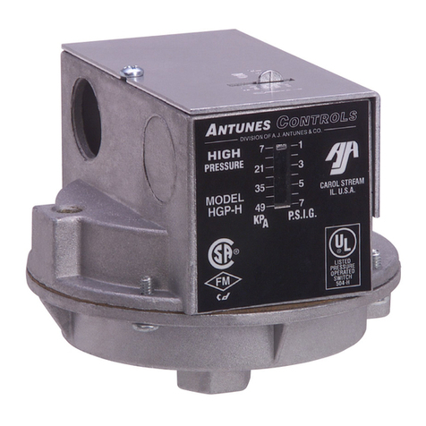
Antunes Controls Gas Pressure Switches moni-
tor gas pressure. The models are available in
high pressure and low pressure single gas
switches. Pressure range varies from .5" of
water column to 4 psi.
Each switch is adjustable within its range, as
shown on the range scale located on top of the
unit. The latch button in the reset models, and
the optional neon light in the recycle models,
show whether the switch is on or off.
The Model G is sturdy, compact and cost
effective. All components are well made.
The switch is neat in appearance with its durable
plastic electrical housing and die cast aluminum
base. In every way you will be pleased with the
ease of installation and the reliability of Antunes
Controls Gas Pressure Switches.
Please read these instructions carefully to
ensure correct installation. This equipment must
be installed by a licensed electrician who is
experienced with combustion safeguard control
systems and understands the functions of inter-
locking switches such as air and gas pressure
switches. Prior to being put into operation with
combustion safeguard systems, all switches
should be tested for proper range setting and
wiring. Check piping connections and switch
housing for leaks with a soap bubble test. All
exhaust fans and blowers should be inspected
and checked for proper rotation prior to start up.
If you have any problems or questions, phone,
fax or write to Antunes Controls at the numbers
listed on the back page of this instruction sheet.

MODEL – G
Gas Pressure Switches
GGI 1010810019 Page 2 Printed in USA 0700
ELECTRICAL
Ratings
10A @ 125 VAC
10A @ 250 VAC
1/3 HP, 125 & 250 VAC
Adjustable Operating Pressure
.5W.C. to 4 psi (different ranges)
Surge Pressure
15 psi (1 Bar)
Maximum Operating Pressure
6 psi (400 mbar)
Ambient Operating Pressure
-40°F to 140°F (-40°C to 60°C)
Field wiring to be rated @ 60°C for maximum 140°F
ambient.
COM
P
NO
NC
Diagram Shows Pressure
Being Applied To Switch
COM
P
NO
NC
Diagram Shows Pressure
Being Applied To Switch
LOW PRESSURE
When pressure decreases below setpoint
NO opens, NC closes
HIGH PRESSURE
When pressure increases above setpoint
NO closes, NC opens
COM
Ground NONC 1/2" Conduit Nut
Connect to Common (COM)
1/2" Conduit
Attach 1/2" Conduit Fitting
to Switch with 1/2" Conduit Nut
Depending on Switch Operation
Connect to Norma y OPEN (NO)
or Norma y CLOSED (NC)
Cutaway View of
Switch to Show
Connection to Ground
Connect Separate Ground
Wire to Ground as Shown
(if required by oca e ectrica code)
CONDUIT CONNECTIONS
COM
NC NO
GROUND
DIN CONNECTOR WIRING

MODEL – G
Gas Pressure Switches
GGI 1010810019 Page 3 Printed in USA 0700
MOUNTING
All switches can be mounted in either horizontal or ver-
tical position. Switches should be reasonably level but
do not required accurate levelling.
Single gas switch models have a 1/4" N.P.T. (female)
gas inlet on the standard base.
Piping can be either standard black pipe or aluminum
tubing.
All switches can be supported by the inlet pipe, but
optional mounting brackets and bases are available
(see Figures 1 thru 5 below).
Switches have been factory calibrated and tested for
leaks. However, it is recommended that switch, gas
pipe inlets and connections be soap bubble tested for
leaks after installation.
OPERATION
Low Gas Pressure Models
Low gas pressure switches break the electrical circuit
on pressure drop at the point when gas pressure
becomes lower than the indicated set pressure.
Before the manual reset button (figure 6) can be prop-
erly latched, gas pressure in the chamber must be
higher than the indicted setting. The position of the
yellow ring, on the reset button, shows whether the
reset button is on or off. If the yellow ring on the but-
ton is below the cover, the unit is on (not latched). If
the yellow ring is above the cover, the unit is off
(latched). The yellow ring must be below the cover
after latching to be properly set.
High Gas Pressure Models
High gas pressure switches break the electrical circuit
when pressure rises above the indicated preset pres-
sure. The yellow ring will be below the cover, indicat-
ing that the switch is on, when the gas pressure in the
switch chamber is below the indicated high setting.
When the yellow ring on the reset button is above the
cover, it indicates the switch is in the off position, and
gas pressure is above the indicated setting.
Range Adjustment - All Models
To adjust gas pressure cut-off setting, remove the
cover. Turn the range scale adjustable knob (Figure 6)
clockwise to increase pressure setting, counterclock-
wise to decrease pressure setting. Install cover and
tighten the two cover screws to prevent tampering.
Figure 6
Figure 1
Figure 5
Figure 2 Figure 3 Figure 4
RANGE SCALE
(ADJUSTABLE KNOB)
RESET BUTTON
RHGP-G or RLGP-G
HGP-G or LGP-G
OPTIONAL SWITCH BASE SIDE
MOUNTING SUGGESTIONS
WITH “O” RING
OPTIONAL SWITCH BASE
SIDE-BY-SIDE MOUNTING
SUGGESTIONS HIGH AND
LOW GAS PRESSURE
OPTIONAL SWITCH BASE
BOTTOM MOUNTING
SUGGESTIONS WITH “O” RING
STANDARD SWITCH BASE
REMOTE MOUNTING
SUGGESTIONS
STANDARD SWITCH BASE
PANEL MOUNTING
SUGGESTIONS

GGI 1010810019 Page 4 Printed in USA 0700
MODEL – G
Gas Pressure Switches
SPECIFICATIONS
Models
RESET
LGP-G Single Unit, Lo-Pressure
HGP-G Single Unit, Hi-Pressure
These part numbers are for standard ¼" N.P.T. gas inlet and
½" electrical knockout.
NOTE: For optional NEMA 4 Kit, 4-Pin DIN Connector, Neon
Lamp Indicator, or Side Mounting, contact Antunes
Controls for specific part numbers.
LOW RANGES AVAILABLE
Part No. W.C. mbar
LGP-G 8103116101 .5"- 4" 1-10
8103116202 1"- 20" 3-50
8103116303 5"- 30" 13-75
8103116407 7"- 55" 17-136
HIGH RANGES AVAILABLE
Part No. W.C. mbar
HGP-G 8101111202 2"- 20" 5-50
8101111303 8"- 35" 18-87
8101111407 10"- 60" 25-150
DIMENSIONS
Limitation of Liability. If it is understood and agreed that seller’s liability whether in contract, in tort, under any warranty, in
negligence or otherwise, shall not exceed the return of the amount of the purchase price paid by purchaser and under no
circumstances shall seller be liable for special, indirect or consequential damages. The price stated for the equipment is a con-
sideration in limiting seller’s liability. No action, regardless of form, arising out of the transactions may be brought by purchaser
more than one year after the cause of action has accrued.
180 KEHOE BLVD. • CAROL STREAM, IL 60188 USA • 1-800-253-2991
www.antunescontrols.com
TEMPERATURE CONTROLLERS • TEMPERATURE DISPLAYS • AIR PRESSURE SWITCHES • GAS SWITCHES • CUSTOM ELECTRONIC CONTROLS
SUBSYSTEMS ENGINEERING AND MANUFACTURING • TIMERS
RECYCLE
RLGP-G Single Unit, Lo-Pressure
RHGP-G Single Unit, Hi-Pressure
OPTIONAL (CONTACT ANTUNES CONTROLS)
NEMA 4 (IP-65) Kit available, Part No. 808000404
4-Pin DIN Connector
Neon Lamp Indicator
Side Mounting
Part No. W.C. mbar
RLGP-G 8104116102 .5"- 4" 1-10
8104116203 1"- 20" 3-50
8104116304 5"- 30" 13-75
PSI Bar
8104118005 1-4 .07-.28
Part No. W.C. mbar
RHGP-G 8102111102 .8"- 4" 3-10
8102111203 2"- 20" 5-50
8102111304 5"- 35" 13-87
PSI Bar
8102113005 1-4 .07-.28
3.000"
(76.2 mm)
(Dimensions are for reference only.)
Ø.875" (22.22mm)
(1/2" Knockout)
Standard
1/4" N.P.T. (Female)
Gas Inlet
Standard Base
Optional
4 Terminal Socket
For DIN Connector
Optional
1/4” BSP (Female)
Yellow
Ring
3.000"
(76.2 mm)
2.670"
(67.8 mm)
.840"
(21.3 mm)
.400" (10.16 mm)
(HGP/LGP Only)
Reset Button
This manual suits for next models
11
Other Antunes Controls Switch manuals
Popular Switch manuals by other brands

Nexxt
Nexxt webwise user manual

Rockwell Automation
Rockwell Automation Allen-Bradley 440G-EZS21STL05J user manual

Pico Macom
Pico Macom TSMS-2150-4A Installation and operation manual

Nolatron
Nolatron TB-2SR owner's manual

Pickering
Pickering LXI 60-770 user manual

D-Link
D-Link DKVM-2K Technical specifications