Any Spot AS-TV8 User manual


Contents
Introduction.............................................................................................1
Before using the TV8 or TV5..................................................................2
Front Panel Configuration of AS-TV8 Series..........................................3
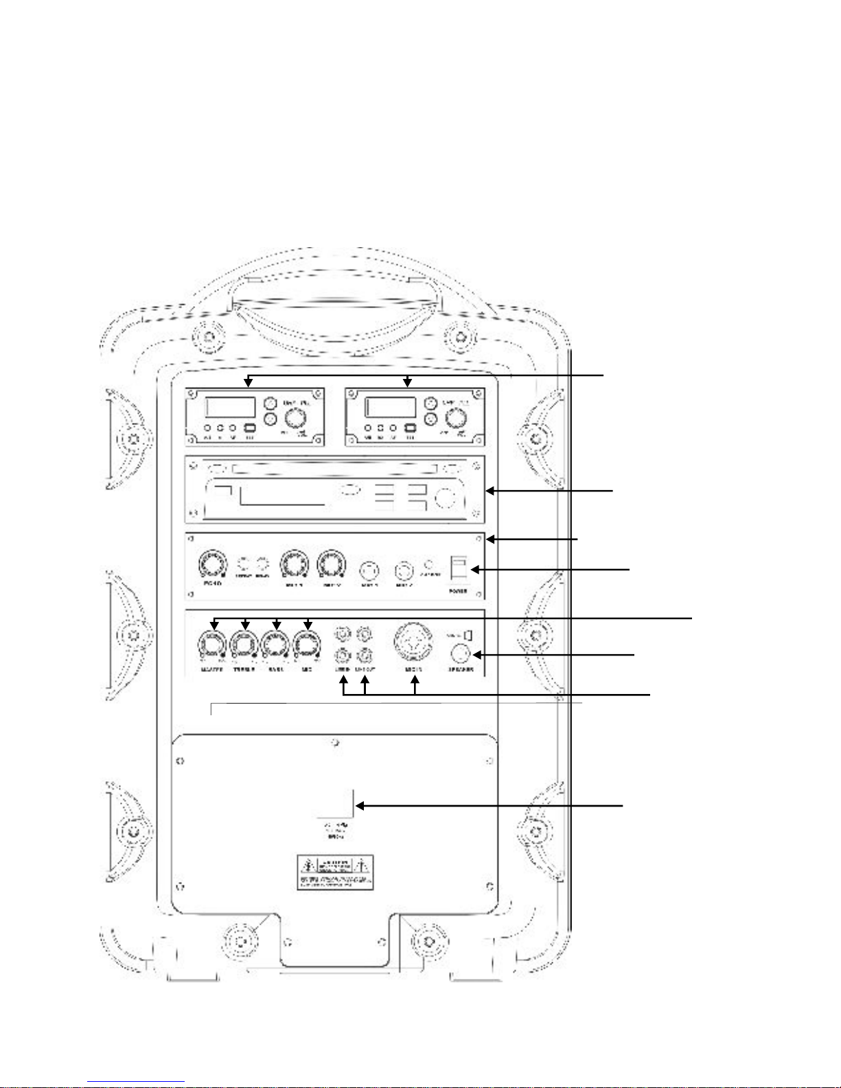
Rear Panel Configuration of AS-TV8 Series ......................................4-6
Description of Functions of AS-TV8 Series.........................................7-9
Operation of the AS-TV8.......................................................................10
Power Supply/Charger..........................................................................10
Power Switch........................................................................................10
Mixer.....................................................................................................10
In/Out Jacks..........................................................................................10
Speaker Out Jack.................................................................................10
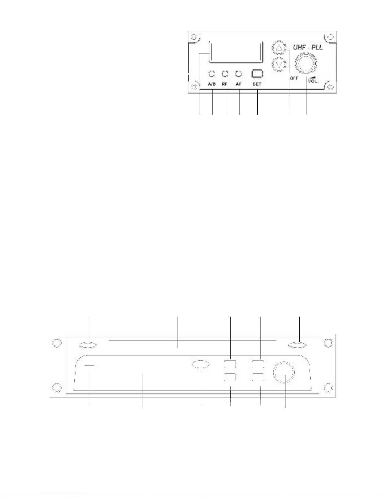
Wireless Mic/Audio Link Receiver ........................................................11
Anti Shock CD/CMP Player...................................................................11
Digital Echo System..............................................................................12
Audio Link Transmitter..........................................................................12
Rear Panel of AS-TV5 Series………..........………………………..........13
Operation of TV5 and Optional Modules…………………………..........14
Optional Wireless Receivers...……………………………………...........14
Description of Functions for Handheld Microphone Front....................15
Description of Functions for Handheld Microphone Back.....................16
Operation of Handheld Microphone.................................................17-19
Description of Functions for Body Pack Transmitter.............................20
Operation of Body Pack Transmitter................................................21-23
AS-TXRM Stationary Transmitter……………………………………. 24-26
Setup and Operation of TXRM…………………………………………...25
Maintenance.........................................................................................23
Specifications..................................................................................26-30
AS-TV8 Series.....................................................................................26
AS-TV5 Series………………………………………………………..........28
Wireless Receiver Module (TV8, TV5)...............…………………..28-29
Digital Echo Module (TV8)...................................................................29
Audio Link Transmitter Module (TV8, TXRM)......................................29
Handheld Microphones...................................................................29-30
Body Pack Transmitter.........................................................................30

Operating Manual for AS-TV8/TV5 Series
**Please visit for the latest updates**www.galaxyaudio.com
Introduction
1
Thank you for purchasing the TV8 / TV5 series wireless portable
sound systems. These units feature an “all in one” design that
allows them to be configured with a variety of different function
modules to suit your specific needs. With rich, full sound and plenty
of power, the TV8 series is ideally suited to cover large areas. The
TV5, with its compact size, is ideal for classrooms, conference
rooms, and guided tours. This manual covers the complete
functions and operations of the TV8 and TV5 including all optional
function modules. It also covers the TXRM Stationary Transmitter,
the TVHH/TVHHC Handheld Wireless Mics, and the TVMBP
Bodypack Transmitter. To use these systems to their fullest
potential please read this manual carefully.

1. Both the TV8 and TV5 use a universal AC switching power supply/charger
that will operate on voltages of 100~240V,50/60Hz. The TV8 power supply is
internal, while the TV5's is external. Verify that the voltage to which you are
connecting is in this range and then connect the AC power cord from the
Traveler to the wall outlet.
2. Charge the battery for at least 8 hours with the Power Switch OFF prior to
first time use to maintain the quality of the battery and provide maximum
operation time. When charging, the charging indicator lights RED. When
charging is almost complete, the indicator will flash alternately RED and
GREEN. After the battery is fully charged, the indicator will light GREEN.
After the initial charge the Traveler may be operated on either AC or Battery
power. When operating on AC power the Traveler will simultaneously
recharge its internal batteries.
3. These units have auto protection circuitry that will protect the battery from
being overcharged or overused. When running on battery power and the
power switch LED blinks RED, the battery power is down to 30%. When the
battery is nearly exhausted, the system will turn off automatically to protect
the battery.
2
Before Using the TV8 or TV5

Front Panel Configuration of AS-TV8 Series
AS-TV8 Series
Heat Sink
Speaker
Grille
8" Woofer
1" Horn
Handle
3

Rear Panel Configuration of AS-TV8C2 Series
AS-TV8C2
Power Supply/
Charging
Input
In/Out
Jacks
Speaker Out
Mixer
Power Switch
CD/CMP Player
Receiver
Modules
4

AS-TV8CE2
Mixer
Receiver
Modules
CD/CMP Player
Digital Echo System
Power Switch
Speaker Out
In/Out
Jacks
Power Supply/
Charging
Input
Rear Panel Configuration of AS-TV8CE2 Series
5

AS-TV8CT2
Mixer
Receiver
Modules
CD/CMP Player
Audio Link
Transmitter
Speaker Out
In/Out
Jacks
Power Supply/
Charging
Input
Power Switch
Rear Panel Configuration of AS-TV8CT2 Series
6

7
(2)(1) (3)
(1)
(2)
(3)
(3)
(2)
(1)
(1)
A. Power Supply/Charging Input
1. AC Power Cable connector
2. Batteries (behind cover)
3. Battery cover
B. Power Switch and Charge Indicator
1. Power LED
2. Charging indicator
3. Power On/Off switch
C. Mixer
1. Master volume control
2. Treble control
3. Bass control
4. Mic volume control
(For wired Mic connected
to Mic in jack D3)
D. In/Out Jacks
1. Line in RCA jacks
2. Line out RCA jacks
3. Mic in XLR/1/4" jack
E. Speaker Out
1. Speaker level output jack.
Minimum 8 ohm external speaker
(2)(1) (3) (4)
Description of Functions for AS-TV8 Series

8
F. Wireless Microphone/Audio Link Receiver (AS-TV8/TV5)
1. LCD display
2. A/B diversity indicator
3. RF indicator
4. AF level indicator
5. Channel Set
6. Channel selector
7. Power switch & mic. volume
G. Anti-Shock CD/CMP Player
1. Program Playlist
2. Power switch
3. LCD display
4. Shuffle/Repeat
5. Stop/Eject
6. Search and play the previous track
7. Search and play the next track
8. Play/Pause
9. CD volume
10. CD slot
11. CMP Folder(Compressed Media Player)
(2)(1) (3)(4) (5) (6) (7)
(1)
(2) (3)
(5)(4) (8)
(9)
(10)
(11) (6) (7)

H1. Digital Echo System (for AS-TV8CE2 )
1. Master echo volume control
2. Delay repeat control
3. Delay time control
4. Wired mic 1 volume control
5. Wired mic 2 volume control
6. Wired mic 1-1/4" input jack
7. Wired mic 2-1/4" input jack
H2. Audio Link Transmitter (AS-TV8CT2)
1. LCD display
2. TX indicator
3. Low audio level indicator
4. High audio level indicator
5. Enter Setting
6. Channel selector
7. Power switch and volume control
(1)
(1)
(2)
(2)
(3)
(3)
(4)
(4)
(5)
(5)
(6)
(6)
(7)
(7)
9

Operation of TV8 Portable Sound System
A. Power Supply/Charger (see page 7)
1. There is a universal AC switching power supply/charger built into the system
that will operate on voltages of 100~240V,50/60Hz. Verify that the voltage to
which you are connecting is in that range and then connect the AC power
cord from the AC IN (A1) to the wall outlet.
B. Power Switch and Charge Indicator (see page 7)
1. Power LED lights constant red under normal operation when power switch is
on. Blinking Power LED indicates 30% of battery power remaining.
2. When charging is almost complete, the indicator will flash RED and GREEN.
After the battery is fully charged, the indicator lights GREEN. The Universal
Power Supply/Battery Charger allows the Traveler to be used anywhere in
the world. The Traveler will operate for an unlimited time on AC power and
for about 6 hours on just battery power. A full recharge of the batteries takes
about 4 hours. The Traveler may be operated while recharging the batteries
without affecting the charge time. If a power failure occurs when operating
on AC, the Traveler will seamlessly switch over to battery power.
C. Mixer (see the page 7)
1. Master Volume Control.
2. Turn the Treble control (C2) counterclockwise to decrease the treble,
and turn clockwise to increase the treble. The center position (straight up)
produces a flat response.
3. Turn the Bass control (C3) counterclockwise to decrease the bass, and
turn clockwise to increase the bass. The center position (straight up) produces
a flat response.
4. Mic Volume for wired mic In jack (D3).
D. In/Out Jacks (see page 7)
1. The system contains Line In, Line Out, and Mic in jacks for connecting
external audio devices.
2. Line In (D1): RCA jacks to connect external audio sources, such as CD/
MP3 players or iPods. The volume of the Line In is controlled solely by the
Master (C1).
3. Line Out (D2): RCA jacks for sending the entire mix signal to other audio
devices, such as recorders, mixers, or power amps.
4. Mic In (D3): XLR or 1/4” (6.3mm) phone jack for wired microphones. Volume
of this input is controlled by Mic In (C4) and the Master (C1).
E. Speaker Out: (see page 7)
1. Used to connect to an external unpowered speaker (8Ω Min.)
10

F. Wireless Mic/Audio link Receiver (see page 8)
This system may include one or two receivers with selectable PLL 96 channel
operation. These modules receive signals from wireless Mics or from another
Traveler equiped with an Audio Link Transmitter.
1. Turn the power switch (F7) clockwise to turn on the receiver.
2. The LCD display (F1) will show “On” and the channel that was last in use
when the unit was turned off.
3. To select a different channel, press the set button (F5). The channel number
will flash in the in LCD display. Press the up or down button (F6) to select a
channel to use, and then press the set button. After a channel has been set,
press either the up or down button to display the frequency of the selected
channel.
4. Adjust the volume control to the desired level.
5. When receiving signal, the A/B diversity indicator (F2) will light RED or Green
to show the normal condition. The RF indicator (F3) will light to show RF
received and the AF indicator (F4) will show audio received.
G. Anti-Shock CD/CMP Player (see page 8)
1. Push the powerswitch (G2) to turn on the player. Put a CD in the CD slot
(G10) or push the Stop/Eject button (G5) to take a CD out of the slot.
2. Press the Play/Pause button (G8) to start or pause CD/MP3 play .Turn the
volume control (G9) to adjust to the proper volume. Push the Stop/Eject button
to stop or change the CD or CMP (Compressed Media Player) disc.
3. Press the Forward (G7) or Reverse (G6) button to skip forward to the next rack
or reverse to the previous track. Holding down the Forward or Reverse button
will continuously forward or reverse the tracks.
4. Repeat/Shuffle (G4) has three modes:
1. Repeat one song
2. Repeat all songs
3. Shuffle for random play.
5. Create Program Playlist:
Step 1: Press Prog button (G1) to begin setting up the program playlist
Step 2: Select a song (see step 3 and 6)
Step 3: Press Repeat (G4) to enter the song. Repeat steps 2 and 3 to enter
additional songs.
Step 4: Press Play (G4) to play the programmed songs in memory
*Please note that the program will reset once the Program button is pressed
again.
6. To select a folder from an CMP, press Folder button (G11). Use Forward or
Reverse buttons to select a song.
11

H1. Digital Echo System (see page 9)
1. Turn the Echo Control (H1-1) clockwise to turn on the echo system. Then
use this control to adjust the level of echo in the mix. Echo will be applied to all
3 mic inputs.
2. Adjust the repeat button (H1-2) to select the number of repeats desired.
Adjust the delay button to select the delay time.
3. Mic input jacks (H1-6 and H1-7) are provided for connecting wired Mics. Mic
volume is controlled by H1-4 and H1-5 plus the Master (C-1, Pg.7).
H2. Audio Link Transmitter (see page 9)
This module transmits the entire audio mix from one Traveler to another Traveler
equiped with a wireless Mic/Audio Link Receiver.
1. Turn the power switch (H2-7) clockwise to turn on the transmitter.
2. The LCD display (H2-1) will show “On” and the channel in use when the unit
was last turned off.
3. To select a different channel, press the set button (H2-5) and the channel will
flash in the LCD display. Press the up or down button (H2-6) to select the
transmit channel, and then press the set button again to enter the setting. The
LCD will then automatically display the selected channel. To display the
frequency of the selected channel press and hold either the up or down button.
4. Turn the volume control (H2-7) to adjust the audio transmit level. Use this
control in conjunction with the volume controls on the receiving Traveler.
5. When transmitting signal, the TX indicator (H2-2) will light Green to
show the transmitting condition. The AF Level indicator lights Yellow (H2-3) to
show a low audio level and lights Red (H2-4) to show high audio level.
6. Set up the receiving Traveler according to the procedure outlined in: F.
Wireless Mic/Audio Link Receiver on page 9. Select the same channel chosen
on the transmitting Traveler.
12

I. Rear Panel of TV5.
J. AS-TVF Optional Media Player for TV5
(2)
(11) (10) (9) (8)
(1) (2) (3) (4) (5) (6) (7)
(9)(8) (10) (11)
(7) (6) (5)
(1)
(3)
(4)
1. DC Power Input
2. Power Switch
3. Power LED
4. Charge LED
5. Aux Out Jack
6. Aux In Jack
7. 1/4" Mic Input
8. Mic Volume
9. Aux Volume
10. Tone Control
11. Master Volume
12. Battery Cover Plate
1. Power Switch
2. LCD
3. Previous Track Button
4. Next Track Button
5. Repeat Button
6. Stop Button
7. Play/Pause Button
8. SD Card Slot
9. Pitch Control
10. USB Jack
11. Volume
13
(12)

Operation of TV5 and Optional Modules (See Page 13)
1. For AC power operation or Charging: Connect the DC end of the
Power Supply/Charger cable to the DC In Jack (I1). Then connect the
other end (AC plug) to the AC wall outlet.
2. See page 2 for more information on Charging, Power Switch, and LED
Indicators.
3. The Aux Out Jack (I5) provides a Pre-Master, Pre-Tone line level
output of the entire mix.
4. The Aux In Jack (I6) is a line level input and is controlled by the Aux
Volume (I9).
5. The ¼" Mic Input (I7) will accept balanced or unbalanced, high or low
impedance mic signals, and is controlled by the Mic Volume (I8).
6. Turn the Tone control (I10) to the left for more bass and to the right for
more treble. This affects the entire mix of inputs, but not the Aux Out
signal.
7. The Master Volume (I11) controls the overall volume of the entire mix,
but has no effect on theAux Out signal.
J. AS-TVF Optional Media Player. (See page 13)
1. The TVF will play audio in the MP3 format from either SD Cards or
USB Devices. Press (J1) to switch on the power. The LCD (J2) will
display “C” when an SD card is inserted into the slot (J8), or display
the “USB symbol” when a USB device is plugged into the USB Jack
(J10). Track number, time counter, and play/pause status will also be
displayed. To switch from one format to the other, simply unplug one
media device and plug in the other.
2. Normal track play functions are controlled by buttons (J3) thru (J7).
The Repeat button (J5) offers three modes: Off, repeat track, and
repeat all tracks.
3. (J11) controls the volume. The Pitch (speed) of playback may be
altered up or down using (J9). For normal Pitch set the control to the
center detent.
For a Description and Operation of the Optional Wireless Microphone
Receiver (TVREC) (see pages 7 and 11).
Notice: Changes or modifications not expressly approved by the party responsible
for compliance could void the user's authority to operate the equipment.
IMPORTANT NOTE: To comply with the FCC RF exposure compliance
requirements, no change to the antenna or the device is permitted. Any change
to the antenna or the device could result in the device exceeding the RF
exposure requirements and void the user's authority to operate the device.
This device complies with Part 15 of the FCC Rules. Operation is subject to the
following two conditions: (1) this device may not cause harmful interference, and
(2) this device must accept any interference received, including interference that
may cause undesired operation.
14

Description of Functions for Handheld Microphone
AS-TVHH/TVHHC
Wind Screen:
Pop Filter. Protects cartridge with
Front Panel
Main Body: Contains Wireless
Transmitter PCB.
SET button for channel settings
LCD panel: Channel and frequency display.
UP and DOWN buttons: For Channel select and
Frequency display.
LED: Power status
Power Switch:
Charging Input: Remove lower housing to
access. 15

Description of Functions for Handheld Microphone
AS-TVHH/TVHHC
Rear Panel
HI LOW MUTE
Volume Control: Three level settings, including
mute, LOW and HI.
Pushing point: Slide the battery cover down by
pressing here.
Battery Cover
Lower Housing: Remove to slide battery cover off or
to connect charger
HI
LOW
16

Operation of Handheld Microphone AS-TVHH/TVHHC
A. Battery Installation Steps:
1. Turn off the microphone before inserting batteries.
2. Press in the latch to release the lower housing and slide it off.
3. Press in the latch to release the battery cover and slide it down.
4. Insert 2 disposable batteries of 1.5V type or 2 rechargeable batteries of 1.2V
type.
5. Observe proper polarity while inserting batteries.
6. Slide the battery cover back to its original position.
7. Install the lower housing back to the lower part of the microphone.
B. Switch-On Steps:
1. Press the power switch and hold for about two seconds until the LED
turns to RED and "on" is displayed in the LCD.
2. The LCD will then automatically display the selected channel.
:Channel indicator.
:Press and hold the Up or Down button to display the
corresponding frequency.
C. Switch Off steps:
1. Press and hold power switch for about two seconds until the LCD displays
OFF.
D. Channel/Frequency Settings (with power on):
1. Press the SET button and hold for about 2 seconds.
2. The Channel number display will start flashing.
3. Press the Up button to display a higher numbered channel.
17

4. Press the Down button to display a lower numbered channel.
5. Press the SET button to activate the selected channel.
E. LCD Indications:
1. :Three bars means batteries are fully charged.
2. :One bar indicates low batteries. Replace or recharge the
batteries.
3. :No bars showing indicates batteries are exhausted and after
flashing three times the power will automatically shut off.
F. Battery Charging Steps:
1. Rechargeable batteries need to be NiMH AA 1.2V with an amperage of
2100mAH or less as the charging function is limited to batteries of that
rating.
2.Recharging is best accomplished by using the AS-DCTVHH charger
3. Charging status:
a. Battery indicator flashing: Non-Rechargeable batteries installed or
no batteries installed. Check the batteries.
b. Battery indicator is flashing and LCD backlight is on: Failing,
corroded, or over-temperature batteries.
c. One or two bars showing: Batteries are charging successfully.
d. Three bars showing: Batteries have been fully charged.
* Please note the microphone will be turned off automatically while it is being
charged.
18
This manual suits for next models
1
Table of contents