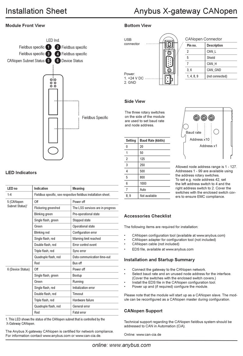
Anybus CompactCom 40 EtherNet/IP Installation and maintenance instructions

+$/067$'&+,&$*2.$5/658+(72.<2%(,-,1*0,/$1208/+286(&29(175<381(&23(1+$*(1
HMS Industrial Networks
Mailing address: Box 4126, 300 04 Halmstad, Sweden
Visiting address: Stationsgatan 37, Halmstad, Sweden
Network Guide
Anybus®CompactCom 40 EtherNet/IP
Doc.Id. HMSI-27-212
Rev. 1.5

Important User Information
This document is intended to provide a good understanding of the functionality offered by EtherNet/IP. The docu-
ment only describes the features that are specific to the Anybus CompactCom 40 EtherNet/IP. For general infor-
mation regarding the Anybus CompactCom 40, consult the Anybus CompactCom 40 design guides.
The reader of this document is expected to be familiar with high level software design, and communication sys-
tems in general. The use of advanced EtherNet/IP-specific functionality may require in-depth knowledge in Ether-
Net/IP networking internals and/or information from the official EtherNet/IP specifications. In such cases, the
people responsible for the implementation of this product should either obtain the EtherNet/IP specification to gain
sufficient knowledge or limit their implementation in such a way that this is not necessary.
Liability
Every care has been taken in the preparation of this manual. Please inform HMS Industrial Networks AB of any
inaccuracies or omissions. The data and illustrations found in this document are not binding. We, HMS Industrial
Networks AB, reserve the right to modify our products in line with our policy of continuous product development.
The information in this document is subject to change without notice and should not be considered as a commit-
ment by HMS Industrial Networks AB. HMS Industrial Networks AB assumes no responsibility for any errors that
may appear in this document.
There are many applications of this product. Those responsible for the use of this device must ensure that all the
necessary steps have been taken to verify that the applications meet all performance and safety requirements in-
cluding any applicable laws, regulations, codes, and standards.
HMS Industrial Networks AB will under no circumstances assume liability or responsibility for any problems that
may arise as a result from the use of undocumented features, timing, or functional side effects found outside the
documented scope of this product. The effects caused by any direct or indirect use of such aspects of the product
are undefined, and may include e.g. compatibility issues and stability issues.
The examples and illustrations in this document are included solely for illustrative purposes. Because of the many
variables and requirements associated with any particular implementation, HMS Industrial Networks AB cannot
assume responsibility for actual use based on these examples and illustrations.
Intellectual Property Rights
HMS Industrial Networks AB has intellectual property rights relating to technology embodied in the product de-
scribed in this document. These intellectual property rights may include patents and pending patent applications
in the US and other countries.
Trademark Acknowledgements
Anybus ® is a registered trademark of HMS Industrial Networks AB. All other trademarks are the property of their
respective holders.
Warning: This is a class A product. In a domestic environment this product may cause radio interference in
which case the user may be required to take adequate measures.
ESD Note: This product contains ESD (Electrostatic Discharge) sensitive parts that may be damaged if ESD
control procedures are not followed. Static control precautions are required when handling the prod-
uct. Failure to observe this may cause damage to the product.
Anybus CompactCom 40 EtherNet/IP Network Guide
Rev 1.5
Copyright© HMS Industrial Networks AB
Apr 2016 Doc Id HMSI-27-212
Preface About This Document
Related Documents.................................................................................................................................. 8
Document History ................................................................................................................................... 8
Conventions & Terminology.................................................................................................................. 9
Abbreviations............................................................................................................................................ 9
Support ...................................................................................................................................................... 9
Chapter 1 About the Anybus CompactCom 40 EtherNet/IP
General..................................................................................................................................................... 10
Features.................................................................................................................................................... 10
Beacon Based DLR (Device Level Ring) ........................................................................................... 11
Chapter 2 Basic Operation
General Information.............................................................................................................................. 12
Software Requirements ................................................................................................................... 12
Device Customization ........................................................................................................................... 13
Network Identity ........................................................................................................................... 13
Electronic Data Sheet (EDS)........................................................................................................ 13
EtherNet/IP & CIP Implementation........................................................................................... 14
Web Interface................................................................................................................................. 14
Socket Interface (Advanced Users Only)......................................................................................... 14
Modular Device Functionality ........................................................................................................ 15
QuickConnect................................................................................................................................15
CIP Safety..................................................................................................................................... 15
Communication Settings ....................................................................................................................... 16
Communication Settings in Stand Alone Shift Register Mode......................................................... 17
Diagnostics .............................................................................................................................................. 18
Network Data Exchange....................................................................................................................... 19
Application Data .......................................................................................................................... 19
Process Data.................................................................................................................................. 19
Translation of Data Types............................................................................................................. 19
File System............................................................................................................................................... 20
Overview ........................................................................................................................................ 20
General Information....................................................................................................................... 21
System Files................................................................................................................................... 21
Table of Contents
Table of Contents

Chapter 3 FTP Server
General Information.............................................................................................................................. 22
User Accounts ........................................................................................................................................ 22
Session Example..................................................................................................................................... 23
Chapter 4 Web Server
General Information.............................................................................................................................. 24
Default Web Pages................................................................................................................................. 24
Network Configuration.................................................................................................................. 25
Ethernet statistics page ................................................................................................................... 27
Server Configuration.............................................................................................................................. 29
General Information....................................................................................................................... 29
Index Page..................................................................................................................................... 29
Default Content Types ................................................................................................................... 30
Authorization................................................................................................................................30
Chapter 5 E-mail Client
General Information.............................................................................................................................. 32
How to Send E-mail Messages............................................................................................................. 32
Chapter 6 Server Side Include (SSI)
General Information.............................................................................................................................. 33
Include File.............................................................................................................................................. 33
Command Functions ............................................................................................................................. 34
General Information....................................................................................................................... 34
GetConfigItem()............................................................................................................................. 35
SetConfigItem().............................................................................................................................. 36
SsiOutput().................................................................................................................................... 38
DisplayRemoteUser ....................................................................................................................... 38
ChangeLanguage() ......................................................................................................................... 39
IncludeFile()................................................................................................................................... 40
SaveDataToFile().......................................................................................................................... 41
printf() ........................................................................................................................................... 42
scanf()............................................................................................................................................ 44
Argument Functions.............................................................................................................................. 46
General Information....................................................................................................................... 46
ABCCMessage() ........................................................................................................................... 46
SSI Output Configuration..................................................................................................................... 50

Chapter 7 JSON
General Information.............................................................................................................................. 51
JSON Objects ......................................................................................................................................... 51
ADI.............................................................................................................................................. 51
Module .......................................................................................................................................... 54
Network........................................................................................................................................ 55
Services .......................................................................................................................................... 59
Hex Format Explained................................................................................................................. 59
Example ................................................................................................................................................... 60
Chapter 8 CIP Objects
General Information.............................................................................................................................. 61
Translation of Status Codes.................................................................................................................. 62
Identity Object (01h) ............................................................................................................................. 63
Message Router (02h) ............................................................................................................................ 66
Assembly Object (04h).......................................................................................................................... 67
Connection Manager (06h) ................................................................................................................... 70
Parameter Object (0Fh)......................................................................................................................... 74
DLR Object (47h) .................................................................................................................................. 77
QoS Object (48h) ................................................................................................................................... 78
Base Energy Object (4Eh) .................................................................................................................... 79
Power Management Object (53h)........................................................................................................ 81
ADI Object (A2h) .................................................................................................................................. 83
Port Object (F4h)................................................................................................................................... 85
TCP/IP Interface Object (F5h)........................................................................................................... 87
Ethernet Link Object (F6h).................................................................................................................. 90

Chapter 9 Anybus Module Objects
General Information.............................................................................................................................. 95
Anybus Object (01h).............................................................................................................................. 96
Diagnostic Object (02h) ........................................................................................................................ 97
Network Object (03h) ........................................................................................................................... 98
Network Configuration Object (04h) ................................................................................................. 99
Socket Interface Object (07h) ............................................................................................................ 109
SMTP Client Object (09h) .................................................................................................................. 126
Anybus File System Interface Object (0Ah) .................................................................................... 131
Examples .................................................................................................................................... 144
Network Ethernet Object (0Ch)........................................................................................................ 148
Functional Safety Module Object (11h)............................................................................................ 149
CIP Port Configuration Object (0Dh).............................................................................................. 153
Chapter 10 Host Application Objects
General Information............................................................................................................................ 155
Functional Safety Host Object (E8h)................................................................................................ 156
CIP Identity Host Object (EDh) ....................................................................................................... 158
Sync Object (EEh) ............................................................................................................................... 160
EtherNet/IP Host Object (F8h) ....................................................................................................... 161
Ethernet Host Object (F9h) ............................................................................................................... 171
Application File System Interface Object (EAh) ............................................................................ 174
Appendix A Categorization of Functionality
Basic ....................................................................................................................................................... 187
Extended................................................................................................................................................ 187
Appendix B Implementation Details
SUP-Bit Definition............................................................................................................................... 188
Anybus Statemachine........................................................................................................................... 188
Application Watchdog Timeout Handling....................................................................................... 188
Appendix C Message Segmentation
General................................................................................................................................................... 189
Command Segmentation..................................................................................................................... 190
Response Segmentation....................................................................................................................... 191

Appendix D Secure HICP (Secure Host IP Configuration Protocol)
General................................................................................................................................................... 192
Appendix E Technical Specification
Front View ............................................................................................................................................ 193
Protective Earth (PE) Requirements................................................................................................. 194
Power Supply ........................................................................................................................................ 194
Environmental Specification .............................................................................................................. 194
EMC Compliance................................................................................................................................. 194
Appendix F Timing & Performance
General Information............................................................................................................................ 195
Internal Timing..................................................................................................................................... 195
Startup Delay.............................................................................................................................. 195
NW_INIT Handling................................................................................................................. 195
Event Based WrMsg Busy Time.................................................................................................. 196
Event Based Process Data Delay ................................................................................................. 196
Appendix G Copyright Notice

Doc.Id. HMSI-27-212
Anybus CompactCom 40 EtherNet/IP
Doc.Rev. 1.5
Preface
P. About This Document
For more information, documentation etc., please visit the HMS website, ‘www.anybus.com’.
P.1 Related Documents
P.2 Document History
Summary of Recent Changes (1.4... 1.5)
Revision List
Document Author
Anybus CompactCom 40 Software Design Guide HMS
Anybus CompactCom M40 Hardware Design Guide HMS
Anybus CompactCom B40 Hardware Design Guide HMS
CIP specification, Volumes 1 (CIP Common) and 2 (EtherNet/IP) ODVA
Change Page(s)
Added information about safety to feature section 10
Added CIP Safety section to Basic Operation chapter 15
Added Class 0 Connection details to the Connection Manager (06h) 71
Added Functional Safety Module Object (11h) 149
Added Functional Safety Host Object (E8h) 156
Revision Date Author(s) Chapter(s) Description
1.00 2014-06-04 KeL All First official revision
1.10 2014-07-17 KeL 2, 6, 7, 8, E Misc. updates
1.11 2014-08-27 KaD 2 Major update
1.20 2015-01-09 KeL 7, 8, 9, F Misc. updates
1.30 2015-11-04 KeL 2, 7, 8, 9,
10, 7, E
Misc. updates and corrections
1.4 2016-04-04 KaD 1,7, 8, 10 Misc. updates
1.5 2016-04-22 KaD 1, 2, 9, 10 Safety updates

About This Document 9
Doc.Id. HMSI-27-212
Anybus CompactCom 40 EtherNet/IP
Doc.Rev. 1.5
P.3 Conventions & Terminology
The following conventions are used throughout this manual:
• Numbered lists provide sequential steps
• Bulleted lists provide information, not procedural steps
• The terms ‘Anybus’ or ‘module’ refers to the Anybus CompactCom 40 module.
• The terms ‘host’ or ‘host application’ refers to the device that hosts the Anybus module.
• Hexadecimal values are either written in the format NNNNh or the format 0xNNNN, where
NNNN is the hexadecimal value.
P.4 Abbreviations
P.5 Support
For general contact information and where to find support, please refer to the contact and sup-
port pages at www.anybus.com.
Abbreviation Meaning
API assigned packet interval
RPI requested packet interval
T target (in this case the module)
O origin (in this case the master)

Doc.Id. HMSI-27-212
Anybus CompactCom 40 EtherNet/IP
Doc.Rev. 1.5
Chapter 1
1. About the Anybus CompactCom 40 EtherNet/IP
1.1 General
The Anybus CompactCom 40 EtherNet/IP communication module provides instant Ethernet and Eth-
erNet/IP connectivity via the patented Anybus CompactCom host interface. Any device that supports
this standard can take advantage of the features offered by the module, allowing seamless network inte-
gration regardless of network type. The module supports both linear and ring network topology (DLR,
Device Level Ring).
The modular approach of the Anybus CompactCom 40 platform allows the CIP-object implementation
to be extended to fit specific application requirements. Furthermore, the Identity Object can be custom-
ized, allowing the end product to appear as a vendor-specific implementation rather than a generic An-
ybus module.
This product conforms to all aspects of the host interface for Anybus CompactCom 40 modules defined
in the Anybus CompactCom 40 Hardware and Software Design Guides, making it fully interchangeable
with any other device following that specification. Generally, no additional network related software
support is needed, however in order to be able to take full advantage of advanced network specific func-
tionality, a certain degree of dedicated software support may be necessary.
1.2 Features
• Two EtherNet/IP ports
• Ethernet RJ45 connectors
• Beacon Based DLR (Device Level Ring) and linear network topology supported
• Black channel interface, offering a transparent channel supporting Functional Safety up to SIL3
with separate safety module1
• 10/100 Mbit, full/half duplex operation
• Web server w. customizable content
•FTPserver
• Email client
• Server Side Include (SSI) functionality
• JSON functionality
• Customizable Identity Information
• Up to 65535 ADIs
• CIP Parameter Object support
• Expandable CIP-object implementation
• Supports unconnected CIP routing
• Transparent Socket Interface
• Modular Device functionality
• QuickConnect supported
• Multiple IO assembly instances can be created
1. IXXAT Safe T100 recommended

About the Anybus CompactCom 40 EtherNet/IP 11
Doc.Id. HMSI-27-212
Anybus CompactCom 40 EtherNet/IP
Doc.Rev. 1.5
1.3 Beacon Based DLR (Device Level Ring)
Device Level Ring (DLR) is a network technology for industrial applications that uses embedded switch
functionality in automation end devices, such as programmable automation controllers and I/O mod-
ules, to enable Ethernet ring network topologies at the device level. DLR technology adds network re-
silience to optimize machine operation.
Beacon based DLR networks consist of a ring supervisor and a number of ring nodes, and use “beacons”
to detect breaks in the ring. When a DLR network detects a break in the ring, it provides ways to alter-
natively route the data to recover the network. Diagnostics built into DLR products can identify the
point of failure, thus helping to speed maintenance and reduce repair time.
The Anybus CompactCom 40 EtherNet/IP implements the DLR protocol, and it is enabled by default.
The device is able to process and act on beacon frames sent by ring supervisors, and supports beacon
rates down to 100 μs.
If needed, the DLR functionality can be disabled. This can be done by setting attribute 31 (Enable DLR)
in the EtherNet/IP Host Object to False. See “Instance Attributes (Instance #1)” on page 162.

Doc.Id. HMSI-27-212
Anybus CompactCom 40 EtherNet/IP
Doc.Rev. 1.5
Chapter 2
2. Basic Operation
2.1 General Information
2.1.1 Software Requirements
Generally, no additional network support code needs to be written in order to support the Anybus Com-
pactCom 40 EtherNet/IP. However, due to the nature of the EtherNet/IP networking system, certain
restrictions must be taken into account:
• Certain functionality in the module requires that the command ‘Get_Instance_Num-
ber_By_Order’ (Application Data Object, FEh) is implemented in the host application.
• Up to 5 diagnostic instances (See “Diagnostic Object (02h)” on page 97) can be created by the
host application during normal conditions. An additional 6th instance may be created in event of
a major fault.1
• EtherNet/IP in itself does not impose any specific timing demands when it comes to acyclic re-
quests (i.e. requests towards instances in the Application Data Object), however it is generally
recommended to process and respond to such requests within a reasonable time period. The ap-
plication that sends the request, also decides the timeout, e.g. EIPScan employs a timeout of 10
seconds.
• The use of advanced CIP-specific functionality may require in-depth knowledge in CIP network-
ing internals and/or information from the official CIP and EtherNet/IP specifications. In such
cases, the people responsible for the implementation of this product is expected either to obtain
these specifications to gain sufficient knowledge or limit their implementation is such a way that
this is not necessary.
For in-depth information regarding the Anybus CompactCom 40 software interface, consult the general
Anybus CompactCom 40 Software Design Guide.
See also...
• “Diagnostic Object (02h)” on page 97 (Anybus Module Objects)
• Anybus CompactCom 40 Software Design Guide, “Application Data Object (FEh)”
1. This limit is set by the module, not by the network.

Basic Operation 13
Doc.Id. HMSI-27-212
Anybus CompactCom 40 EtherNet/IP
Doc.Rev. 1.5
2.2 Device Customization
2.2.1 Network Identity
By default, the module uses the following identity settings:
• Vendor ID: 005Ah (HMS Industrial Networks)
• Device Type: 002Bh (Generic Device)
• Product Code: 0037h (Anybus CompactCom 40 EtherNet/IP)
• Product Name: ‘Anybus CompactCom 40 EtherNet/IP(TM)’
Optionally, it is possible to customize the identity of the module by implementing the corresponding
instance attributes in the EtherNet/IP Host Object.
See also...
• “Identity Object (01h)” on page 63 (CIP-object)
• “EtherNet/IP Host Object (F8h)” on page 161 (Host Application Object)
IMPORTANT: According to the CIP specification, the combination of Vendor ID and serial number must be unique.
It is not permitted to use a custom serial number in combination with the HMS Vendor ID (005Ah), nor is it permitted
to choose Vendor ID arbitrarily. Failure to comply to this requirement will induce interoperability problems and/or other
unwanted side effects. HMS approves use of the HMS Vendor ID (005Ah), in combination with the default serial num-
ber, under the condition that the implementation requires no deviations from the standard EDS-file.
To obtain a Vendor ID, contact the ODVA.
2.2.2 Electronic Data Sheet (EDS)
On EtherNet/IP, the characteristics of a device is stored in an ASCII data file with the suffix EDS. This
file is used by configuration tools etc. when setting up the network configuration. HMS supplies a stand-
ard (generic) EDS-file, which corresponds to the default settings in the module. However, due to the
flexible nature of the Anybus CompactCom concept, it is possible to alter the behavior of the product
in ways which invalidate the generic EDS-file. In such case, a custom EDS-file needs to be created,
which in turn invalidates the default identity information and require re-certification of the product.
Note: Since the module implements the Parameter Object, it is possible for configuration tools such as
RSNetWorx to automatically generate a suitable EDS-file. Note that this functionality requires that the
command ‘Get_Instance_Number_By_Order’ (Application Data Object, FEh) has been implemented
in the host application.
See also...
• “Parameter Object (0Fh)” on page 74 (CIP-object)
• Anybus CompactCom 40 Software Design Guide, “Application Data Object (FEh)”
IMPORTANT: HMS approves use of the standard EDS-file only under the condition that it matches the actual im-
plementation and that the identity information remains unchanged.

Basic Operation 14
Doc.Id. HMSI-27-212
Anybus CompactCom 40 EtherNet/IP
Doc.Rev. 1.5
2.2.3 EtherNet/IP & CIP Implementation
By default, the module supports the generic CIP profile. Optionally, it is possible to re-route requests to
unimplemented CIP objects to the host application, thus enabling support for other profiles etc.
To support a specific profile, perform the following steps:
• Set up the identity settings in the EtherNet/IP Host Object according to profile requirements.
• Implement the Assembly Mapping Object in the host application.
• Set up the Assembly Instance Numbers according to profile requirements.
• Enable routing of CIP messages to the host application in the EtherNet/IP Host Object.
• Implement the required CIP objects in the host application.
See also...
• “EtherNet/IP Host Object (F8h)” on page 161 (Host Application Object)
• “Command Details: Process_CIP_Object_Request” on page 166
2.2.4 Web Interface
The web interface can be fully customized to suit a particular application. Dynamic content can be cre-
ated by means of JSON and SSI scripting. Data and web pages are stored in a FLASH-based file system,
which can be accessed using any standard FTP-client.
See also...
• “File System” on page 20
• “FTP Server” on page 22
• “Web Server” on page 24
• “Server Side Include (SSI)” on page 33
• “JSON” on page 51
2.2.5 Socket Interface (Advanced Users Only)
The built in socket interface allows additional protocols to be implemented on top of TCP/IP.
See also...
• “Socket Interface Object (07h)” on page 109 (Anybus Module Object)
• “Message Segmentation” on page 189

Basic Operation 15
Doc.Id. HMSI-27-212
Anybus CompactCom 40 EtherNet/IP
Doc.Rev. 1.5
2.2.6 Modular Device Functionality
Modular devices consist of a backplane with a certain number of “slots”. The first slot is occupied by
the “coupler” which contains the Anybus CompactCom module. All other slots may be empty or occu-
pied by modules.
When mapping ADIs to process data the application shall map the process data of each module in slot
order.
A list of modules in a Modular Device is available to the EtherNet/IP network master by a request to
the CIP Identity object.
See also ...
• “Modular Device Object (ECh)” (see Anybus CompactCom 40 Software Design Guide)
• “Identity Object (01h)” on page 63
2.2.7 QuickConnect
The module supports the QuickConnect functionality. It is enabled in the EtherNet/IP Host Object.
The module fulfills Class A with a startup time of less than 180 ms, with 16 bytes of I/O data mapped
with parallel, SPI or shift register application interface.
See also ...
• “EtherNet/IP Host Object (F8h)” on page 161
• “TCP/IP Interface Object (F5h)” on page 87 (CIP object)
2.2.8 CIP Safety
The Anybus CompactCom 40 EtherNet/IP device supports the CIP safety profile. This profile makes
it possible for a user to send data on a black channel interface, i.e. a safe channel over EtherNet/IP using
an add-on safety module, e.g. the IXXAT Safe T100. For an application to support CIP safety, the Func-
tional Safety Object (E8h) has to be implemented.
The Anybus CompactCom serial channel is used for the functional safety communication. When this
channel is used for the host application, a second separate serial channel is implemented for the func-
tional safety communication. See the Anybus CompactCom Hardware Design Guide for more informa-
tion.
See “Functional Safety Host Object (E8h)” on page 156.

Basic Operation 16
Doc.Id. HMSI-27-212
Anybus CompactCom 40 EtherNet/IP
Doc.Rev. 1.5
2.3 Communication Settings
As with other Anybus CompactCom products, network related communication settings are grouped in
the Network Configuration Object (04h).
In this case, this includes...
• TCP/IP settings
These settings must be set properly in order for the module to be able to participate on the net-
work.
The module supports DHCP, which may be used to retrieve the TCP/IP settings from a DHCP-
server automatically. DHCP is enabled by default, but can be disabled if necessary.
• Physical Link Settings
By default, the module uses auto negotiation to establish the physical link settings, however it is
possible to force a specific setting if necessary.
The parameters in the Network Configuration Object (04h) are available from the network through the
built in web server, and through the TCP/IP Interface Object (CIP).
See also...
• “Web Server” on page 24
• “TCP/IP Interface Object (F5h)” on page 87 (CIP)
• “Ethernet Link Object (F6h)” on page 90 (CIP)
• “Network Configuration Object (04h)” on page 99 (Anybus Module Object)
• “Secure HICP (Secure Host IP Configuration Protocol)” on page 192

Basic Operation 17
Doc.Id. HMSI-27-212
Anybus CompactCom 40 EtherNet/IP
Doc.Rev. 1.5
2.3.1 Communication Settings in Stand Alone Shift Register Mode
If the Anybus CompactCom 40 is used stand alone, there is no application from which to set the IP
address. The IP address is instead set using the DIP1 switches (IP address byte 3) and the virtual attrib-
utes (Ethernet Host object (F9h), attribute #17), that are written to memory during setup (IP address
byte 0 - 2). A flowchart is shown below.
See also...
• “Ethernet Host Object (F9h)” on page 171
• Anybus CompactCom M40 Hardware Design Guide
• “Network Configuration Object (04h)” on page 99
Start
DIP1 switch settings
(0 - 255)
2550
1 - 254
Values stored in
Network Conguration
Object instances #3 - #6
will be used
Ethernet
Host Object (F9h),
attribute #17
implemented
Yes
No Use default value for
IP address bytes 0 - 2:
192.168.0.X
Use DIP switch settings
for IP address byte 3
End
Use attribute #17 values
for IP address bytes 0 - 2
IP address is stored in Network
Conguration Object (04h),
instance #3
Check for DHCP
availability
Yes
No
DHCP will be used for
communication settings,
that will be stored in
Network Conguration
Object (04h), instances #3 - #6
Values stored in
Network Conguration
Object instances #3 - #6
will be used
Network Conguration Object (04h)
Instance #4, Subnet mask: 255.255.255.0
Instance #5 Gateway address: 0.0.0.0
Instance 6, DHCP: OFF

Basic Operation 18
Doc.Id. HMSI-27-212
Anybus CompactCom 40 EtherNet/IP
Doc.Rev. 1.5
2.4 Diagnostics
The severity value of all pending events are combined (using logical OR) and copied to the correspond-
ing bits in the ‘Status’-attribute of the Identity Object (CIP).
See also...
• “Identity Object (01h)” on page 63 (CIP)
• “Diagnostic Object (02h)” on page 97 (Anybus Module Object)

Basic Operation 19
Doc.Id. HMSI-27-212
Anybus CompactCom 40 EtherNet/IP
Doc.Rev. 1.5
2.5 Network Data Exchange
2.5.1 Application Data
Application Data Instances (ADIs) are represented through the ADI Object (CIP). Each instance within
this objects corresponds directly to an instance in the Application Data Object on the host application
side.
Accessible range of ADIs is 1 to 65535.
See also...
• “Parameter Object (0Fh)” on page 74 (CIP)
• “ADIObject(A2h)”on page 83 (CIP)
2.5.2 Process Data
Process Data is represented as dedicated instances in the Assembly Object (CIP).
See also...
• “Assembly Object (04h)” on page 67 (CIP)
• “Connection Manager (06h)” on page 70 (CIP)
2.5.3 Translation of Data Types
The Anybus data types are translated to CIP-standard and vice versa as follows:
Anybus Data Type CIP Data Type Comments
BOOL BOOL Each ADI element of this type occupies one byte.
ENUM USINT
SINT8 SINT
UINT8 USINT
SINT16 INT Each ADI element of this type occupies two bytes.
UINT16 UINT
SINT32 DINT Each ADI element of this type occupies four bytes.
UINT32 UDINT
FLOAT REAL
CHAR SHORT_STRING SHORT_STRING consists of a single-byte length field (which in this case
represents the number of ADI elements) followed by the actual character data
(in this case the actual ADI elements). This means that a 10-character string
occupies 11 bytes.
SINT64 LINT Each ADI element of this type occupies eight bytes.
UINT64 ULINT
BITS8 BYTE Each ADI element of this type occupies one byte.
BITS16 WORD Each ADI element of this type occupies two bytes.
BITS32 DWORD Each ADI element of this type occupies four bytes.
OCTET USINT
BITS1-7 BYTE Bit fields of size 1 - 7
PAD0-8 BYTE Bit fields of size 0 - 8 used for padding
PAD9-16 BYTE Bit fields of size 9 - 16 used for padding

Basic Operation 20
Doc.Id. HMSI-27-212
Anybus CompactCom 40 EtherNet/IP
Doc.Rev. 1.5
2.6 File System
Category: Extended
2.6.1 Overview
The Anybus CompactCom 40 EtherNet/IP has an in-built file system, that can be accessed from the
application and from the network. Three directories are predefined:
• VFS - The virtual file system that e.g. holds the web pages of the module.
• Application - This directory provides access to the application file system through the Applica-
tion File System Interface Object (EAh) (optional).
• Firmware - Firmware updates are stored in this directory.
Important: In the firmware folder, it is not possible to use append mode when writing a file. Be
sure to use write mode only.
Anybus
CompactCom
File system
File 1
File 2
VFS
File 1
File 2
Application
Application
File system
File A1
File A2
Directory A1
File A1:1
File A1:2
The Anybus CompactCom accesses
the application file system through the
Application File System Interface Object.
Anybus CompactCom Application
Firmware
Table of contents
Other Anybus Control Unit manuals

Anybus
Anybus CompactCom 30 Installation and maintenance instructions

Anybus
Anybus CompactCom 40 Common Ethernet Guide

Anybus
Anybus CompactCom 40 Modbus-TCP Installation and maintenance instructions

Anybus
Anybus CompactCom 40 Modbus-TCP Installation and maintenance instructions

Anybus
Anybus CompactCom 40 Modbus-TCP Installation and maintenance instructions

Anybus
Anybus X-gateway CANopen Assembly instructions

Anybus
Anybus CompactCom 40 Modbus-TCP Installation and maintenance instructions

Anybus
Anybus CompactCom 40 Modbus-TCP Installation and maintenance instructions

Anybus
Anybus CompactCom 40 Modbus-TCP Installation and maintenance instructions

Anybus
Anybus CompactCom User manual