2
Operating instructions
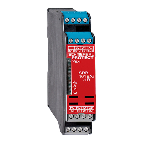
Safety-monitoring module SRB 301MC
EN
1.7 Exclusion of liability
We shall accept no liability for damages and malfunctions resulting from
defective mounting or failure to comply with this operating instructions
manual. The manufacturer shall accept no liability for damages resulting
from the use of unauthorised spare parts or accessories.
For safety reasons, invasive work on the device as well as arbitrary re-
pairs, conversions and modications to the device are strictly forbidden;
the manufacturer shall accept no liability for damages resulting from
such invasive work, arbitrary repairs, conversions and/or modications
to the device.
The safety-monitoring module must only be used when the enclosure is
closed, i.e. with the front cover tted.
2 Product description
2.1 Ordering code
This operating instructions manual applies to the following types:
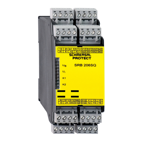
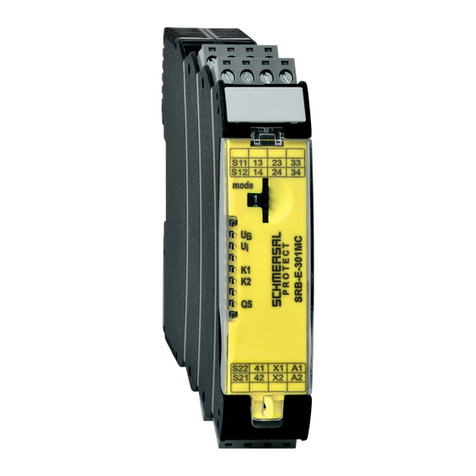
SRB 301MC
Only if the information described in this operating instructions
manual are realised correctly, the safety function and therefore
the compliance with the Machinery Directive is maintained.
2.2 Special versions
For special versions, which are not listed in the order code below 2.1,
these specications apply accordingly, provided that they correspond to
the standard version.
2.3 Destination and use
The safety-monitoring modules for integration in safety circuits are
designed for tting in control cabinets. They are used for the safe
evaluation of the signals of positive break position switches or magnetic
safety sensors for safety functions on sliding, hinged and removable
safety guards as well as emergency stop control devices and AOPD's.
The safety function is dened as the opening of the enabling circuits
13-14, 23-24 and 33-34 when the inputs S11-S12 and/or S21-S22 are
opened.
The safety-relevant current paths with the outputs contacts 13-14, 23-24
and 33-34 meet the following requirements under observation of a PFH
value assessment (also refer to chapter 2.5 "Safety classication"):
– Control category 4 - PL e to DIN EN ISO 13849-1
– SIL 3 to DIN EN 61508-2
– SILCL 3 to DIN EN 62061
(meets the requirements of control category 4 to DIN EN 954-1)
To determine the Performance Level (PL) of the entire safety function
(e.g. sensor, logic, actuator) to DIN EN ISO 13849-1, an analysis of all
relevant components is required.
2.4 Technical data
General data
Standards: IEC/EN 60204-1, EN 60947-5-1;
EN ISO 13849-1, IEC 61508
Climate resistance: EN 60068-2-78
Fixing: Snaps onto standard DIN rails to
DIN EN 60715
Terminal designations: EN 60947-1
Material of the enclosure: glass-bre reinforced thermoplastic,
ventilated
Material of the contacts: AgSnO, self-cleaning, positive drive
Weight: 230 g
Start conditions Automatic or start button
Feedback circuit (Y/N): Yes
Pull-in delay for
automatic start:
typ. 100 ms
Pull-in delay with reset button: typ. 20 ms
Drop-out delay in case
of emergency stop:
typ. 20 ms
Drop-out delay on
"supply failure":
typ. 80 ms
Bridging in case of
voltage drops:
typ. 80 ms
Mechanical data
Connection type: Screw terminals
Cable section: min. 2 mm² / max. 2 mm²
Connecting cable: rigid or exible
Tightening torque for
the terminals:
0.6 Nm
With removable terminals (Y/N): No
Mechanical life: 10 million operations
Electrical life: Derating curve available on request
Resistance to shock: 10 g / 11 ms
Resistance to vibrations
to EN 60068-2-6:
10 ... 55 Hz, amplitude 0.35 mm
Ambient conditions
Ambient temperature: –25°C … +60°C
Storage and transport
temperature:
–40°C … +85°C
Protection class: Enclosure: IP 40,
Terminals: IP 20,
Wiring compartment: IP 54
Air clearances and creepage
distances to IEC/EN 60664-1:
4 kV/2 (basic insulation)
EMC rating: to EMC Directive
Electrical data
Contact resistance in new state: max. 100 mΩ
Power consumption: max. 2.0 W / 4.9 VA
Rated operating voltage Ue1: 24 VDC –15%/+20%,
residual ripple max. 10%
24 VAC –15% / +10%
Frequency range: 50 Hz / 60 Hz
Max. fuse rating of the
operating voltage:
internal electronic fuse,
tripping current > 500 mA,
reset after approx. 1 sec.
Monitored inputs
Cross-wire detection (Y/N): Yes
Wire breakage detection (Y/N): Yes
Earth leakage detection (Y/N): Yes
Number of NO contacts: 0
Number of NC contacts: 2
Cable lengths: 1.500 m with 1,5 mm²
2.500 m with 2,5 mm²
Conduction resistance: max. 40 Ω
Outputs
Number of safety contacts: 3
Number of auxiliary contacts: 1
Number of signalling outputs: 0
Switching capacity of the
safety contacts:
13-14; 23-24;33-34:
max. 250 V, 8 A ohmic (inductive in
case of suitable protective wiring);
min. 10 V / 10 mA, residual current
at ambient temperature up to 45°C:
24 A / 55°C: 18 A / 60°C: 12 A
Switching capacity of
the auxiliary contacts:
41-42:
24 VDC / 2 A
Fuse rating of the
safety contacts:
external (Ik = 1000 A) to EN 60947-5-1
Safety fuse 10 A quick blow, 8 A slow
blow
Recommended fuse for
the auxiliary contacts:
external (Ik = 1000 A) to EN 60947-5-1
Safety fuse 2,5 A quick blow, 2 A slow
blow
Utilisation category
to EN 60947-5-1:
AC-15 / DC-13: EN 60947-5-1
Dimensions (H/W/D): 100 mm x 22.5 mm x 121 mm
The data specied in this manual are applicable when the component
is operated with rated operating voltage Ue±0%.
