manuals.online logo
Brands
  1. Home
  2. •
  3. Brands
  4. •
  5. Anyuta
  6. •
  7. Toy
  8. •
  9. Anyuta Bleriot XI-2 Balkan Wars & WWI User manual

Anyuta Bleriot XI-2 Balkan Wars & WWI User manual

Dear customer,
We thank you for buying our products and we appreciate your interest on
our 1/15 scale Blériot XI-2 airplane model kit, one of our most wanted 3d
printed products, manufactured with frosted ultra detail plastic material.
In case you ‘ll notice slight traces of oil on the kit parts surface when
you got the item, it is absolutely normal. This oil is actually left after the
3D printing process was finished and the kit parts been removed from the
printer tray to be washed into an ultrasonic oil bath and later an
ultrasonic water bath and might escaped the clean inspection and dry by
hand procedure. It can be cleaned easily by washing parts with water &
dishwasher soap. Use an old toothbrush gently & then allow to dry. Keep
in mind that items are only 0.3mm to 0.5mm thin and they are very fragile.
Feel free to ask any help or info during your model building process. You
allready got the assembling instructions in your hands, but we ‘d like you
to know that Anyuta 3D will be always next to you for anything you might
need in order to build a realistic scale model for your showcase.
Regards,
Anyuta 3D print creations & scale models
http://www.shapeways.com/shops/anyuta3D
Blériot XI-2 Balkan Wars & WWI
1/15 scale 3d printed model kit by anyuta creations
The Blériot XI-2 was the XI type’s reconnaissance liaison version with two
seats for pilot and observer, used by many countries during Balkan Wars
& WWI. Blériot XI & XI-2 types remained in production until WWI outbreak.
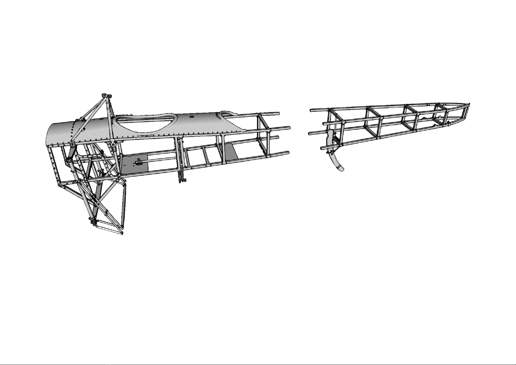
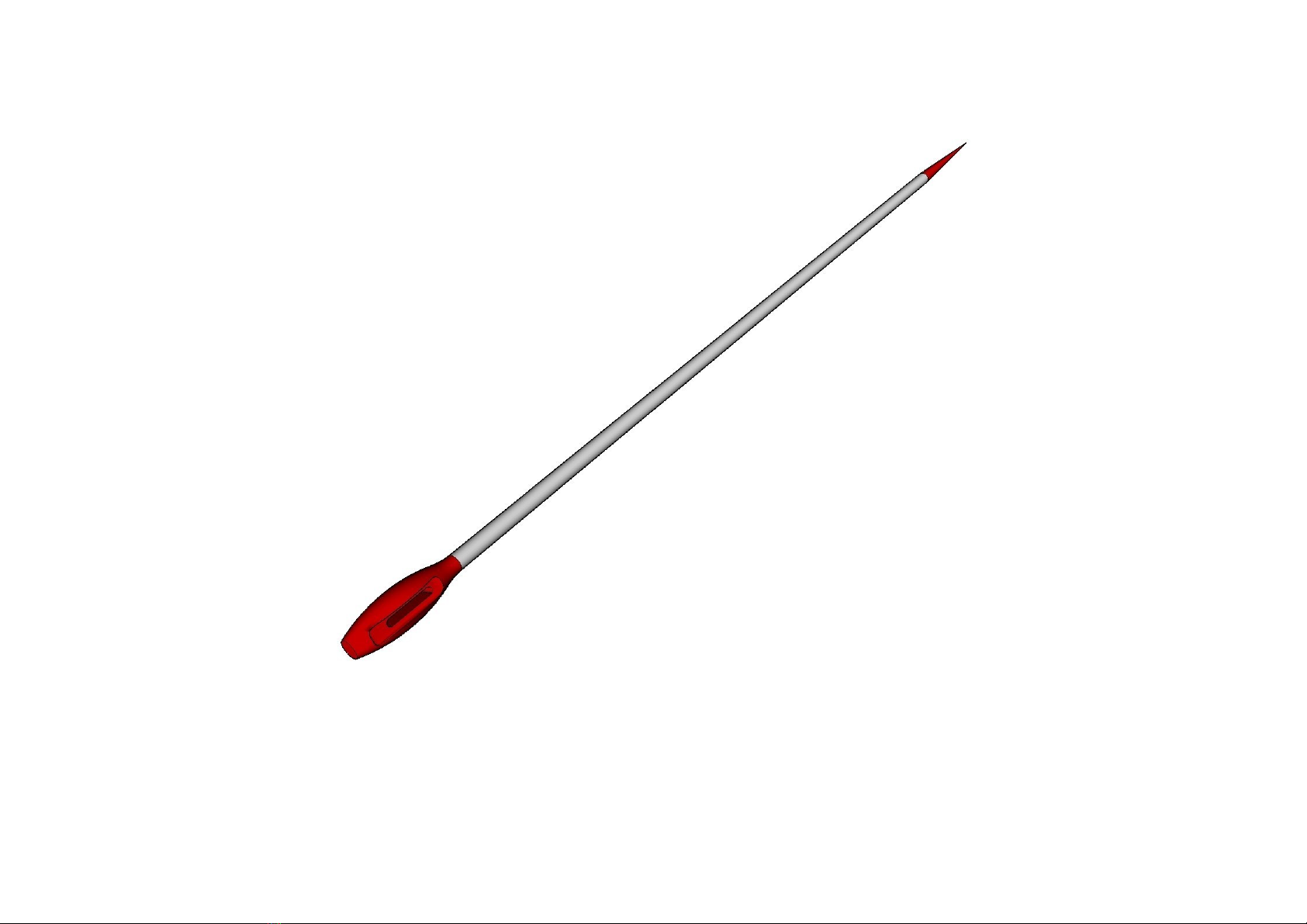
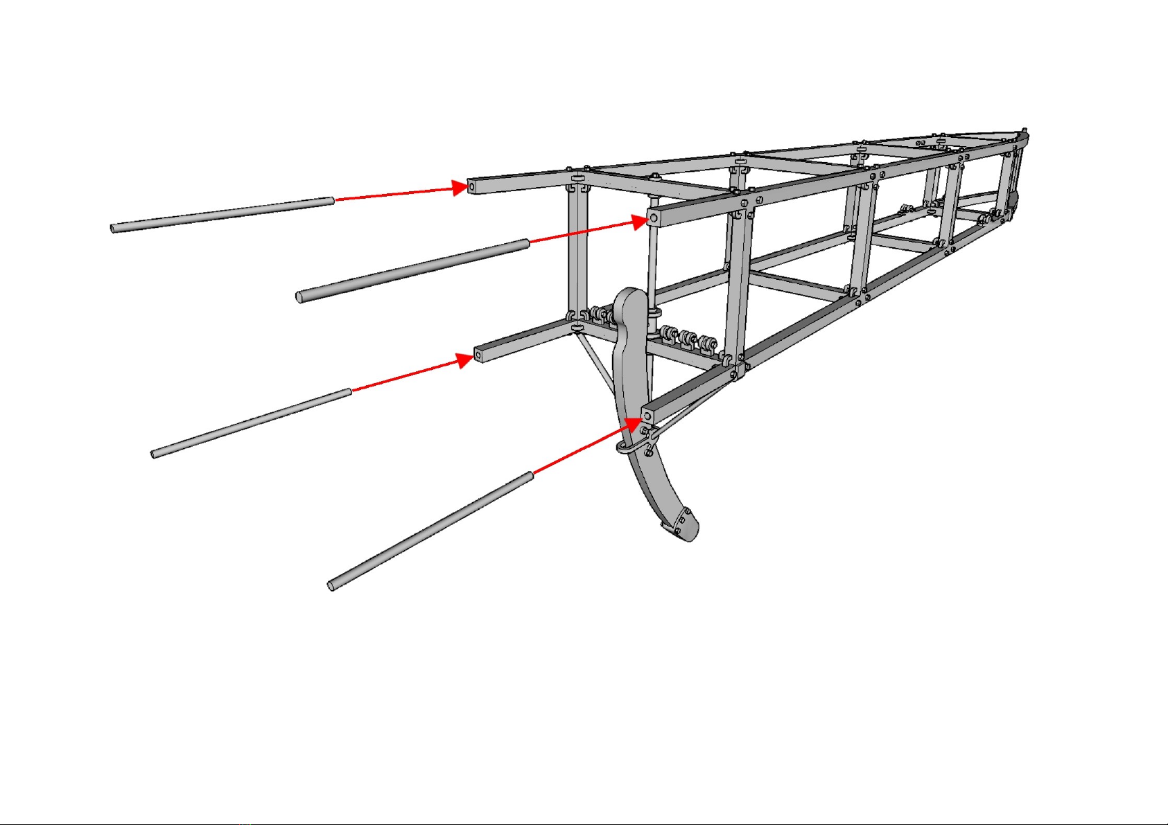
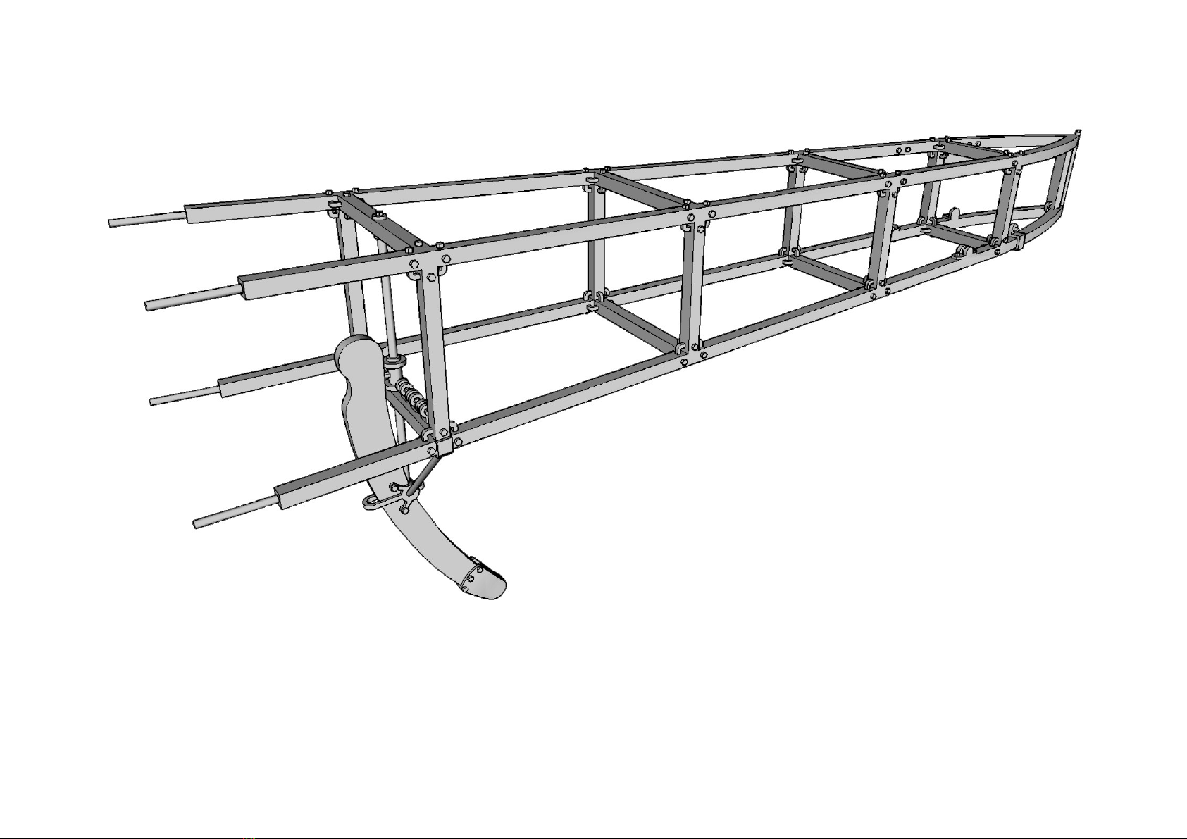
STEP-BY-STEP MODEL KIT BUILDING INSTRUCTIONS
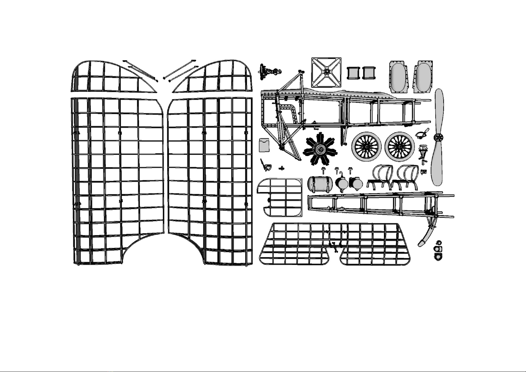
This is a Blériot XI-2 was the XI WWI airplane unassembled model kit
produced under 1/15 scale for aviation or military diorama enthousiasts &
scale modeler builders. This kit contains all necessary parts for
assembling ONE model under 1/15 scale. All parts are 3D printed with
Frosted Ultra Detail matte translucent plastic material, which is highly
recomended for best results on detail. Additional diorama accessories (eg.
Fuel drums & jerrycans, fire extinguisher, wheel chokes etc) are not
included into this model kit and should be purchased separately by
“ANYUTA 3d print creations” products catalog. Please follow the step-by-
step model kit building instructions. Due to parts complexity, the kit is
appropriate for experienced modelers. For additional info, building
instructions & directions, contact with us and we ‘ll be happy to help.
The scale model kit contains 48 parts, 3D printed with Frosted Ultra Detail matte
translucent plastic material. Please check & identify each part closely before
proceeding to building process. Cyanoacrylate glue is recommended for best results.
These are the front and the rear fuselage frame sections. On real Blériot XI and XI-
2
WWI airplanes, fuselage was covered by aluminum, plywood & doped fabric over the
wooden frame. Be sure to check & prepare the fuselage parts before proceeding next.
Due to fact that fuselage consis
ts of front & rear sections, it is necessary to
reinforce the build. Use a common stainless steel sewing needle (approx 50mm long x
1mm wide) and remove bolt & tip (red colour marked). Steel pin should be 40mm long.
Prepare four steel pins & i
nsert them through slots on rear frame section’s beams
as shown on above screenshot. Make sure that fuselage frame section’s beam slots
are clear, so that the metal pins can penetrate to a depth equal to half their length.
This is how the rear fus
elage frame section should look like with the four metal pins
wedged into beam slots. Notice that steel pins should protrude about half of their
length (approx 18 to 20mm) just as much they are wedged into the rear frame beams.
As soon as the four steel p
ins are simultaneously aligned onto front fuselage frame
slots, slide carefully the rear frame section forward (marked with the red arrows) to
fit pins in place. Then, secure the build by adding a drop of cyanoacrylate super glue.
This is how the fuselage s
hould look like when the front & rear sections correctly
assembled to fit onto each other. The metal pins should be equally wedged into each
frame section in order to effectively support parts to be glued & reinforce the build.
These are the fuel & oil tank c
aps. If you intend to leave the fuel or oil tanks opened
and place filler caps nearby, the red colour marked sprue parts should be carefully
removed with modeling knife with a sharp blade. The kit contains three (3) filler caps.
These are the left and right cyli
ndrical shaped engine oil tanks, mounted under the
aluminum hood infront of pilot’s flight controls & gauges. Be sure you identify parts
correctly before proceeding next step. The kit contains two (2) cylindrical oil tanks.
Insert the two cylindrical engin
e oil tanks carefully through the front opening and
place them such way to align on the semicircular brackets, underneath the aluminum
hood in front of pilot’s cockpit. Be careful while inserting tanks to prevent fracture
As soon as each cylindrical e
ngine oil tank is correctly aligned on the semicircular
brackets underneath the aluminum hood, move upwards (marked with red arrows), as
shown on picture. Then, secure in place by adding a drop of cyanoacrylate super glue.
This is how the two cyli
ndrical shaped oil tanks should look like when correctly
installed underneath the aluminum hood. Dry fit testing is recommended before final
assembling. Secure in place with a drop of cyanoacrylate super glue for best results
If the two oil tanks ar
e correctly installed underneath the aluminum hood, the right
tank’s inverse breather pipe (red circle marked) should clearly protrude from hood
opening & both filler caps should be visible & alligned under front circular openings
These are the 7-cylinde
r rotary engine’s front & rear sections. Due the engine’s size,
it cannot pass through the front opening and be installed in place as one piece.
Therefore, it will be assembled in stages. Be sure you identify these parts correctly.
Insert the engine’s re
ar section carefully through the frame opening & place it such
way to align bracket on the second vertical beams. Be careful while inserting the
part, to prevent fracture or damage on the previously installed cylindrical oil tanks.
This is how the engine
’s rear section should look like when it’s bracket is correctly
aligned on the second vertical frame beams (left & right) & placed under oil tanks.
Exact bracket height will be later adjusted depending on front section installation.
Insert engine’s front s
ection through frame opening and slide backwards (red arrow
marked) to fit on engine’s rear section. Since engine’s diameter is wider than frame
opening, you may need to twist part a little, to pass between first left & right beams.

Other Anyuta Toy manuals

Anyuta Werfer Granate BR21 Launcher User manual

Anyuta

Anyuta Werfer Granate BR21 Launcher User manual

Popular Toy manuals by other brands

Hasbro ZORD ASCENSION PROJECT POWER RANGERS IN SPACE ASTRO... quick start guide

Hasbro

Hasbro ZORD ASCENSION PROJECT POWER RANGERS IN SPACE ASTRO... quick start guide

Robinson Helicopter Company R44 II Pilot operating handbook

Robinson Helicopter Company

Robinson Helicopter Company R44 II Pilot operating handbook

marklin 39162 user manual

marklin

marklin 39162 user manual

Oxybul EDUCABUL MY FIRST MICROSCOPE user manual

Oxybul

Oxybul EDUCABUL MY FIRST MICROSCOPE user manual

Lionel 4-6-2 Pacific owner's manual

Lionel

Lionel 4-6-2 Pacific owner's manual

LGB 22871 instruction manual

LGB

LGB 22871 instruction manual

Fisher-Price G6542 instruction sheet

Fisher-Price

Fisher-Price G6542 instruction sheet

Ares Taylorcraft 130 instruction manual

Ares

Ares Taylorcraft 130 instruction manual

Fisher-Price FNV41 instruction sheet

Fisher-Price

Fisher-Price FNV41 instruction sheet

REVELL C-17A Globemaster III Assembly manual

REVELL

REVELL C-17A Globemaster III Assembly manual

Tiger Electronics Petal-Chi 59757 instructions

Tiger Electronics

Tiger Electronics Petal-Chi 59757 instructions

INTERACTIVE TOY CONCEPTS LIGHTENING BUG instruction manual

INTERACTIVE TOY CONCEPTS

INTERACTIVE TOY CONCEPTS LIGHTENING BUG instruction manual

Phoenix Model F4U Corsair instruction manual

Phoenix Model

Phoenix Model F4U Corsair instruction manual

Connoisseur Models GWR Loriot M instructions

Connoisseur Models

Connoisseur Models GWR Loriot M instructions

Fisher-Price BHB14 instruction manual

Fisher-Price

Fisher-Price BHB14 instruction manual

arf BH67 instruction manual

arf

arf BH67 instruction manual

GAUGEMASTER Structures GMKD1002 manual

GAUGEMASTER

GAUGEMASTER Structures GMKD1002 manual

Mega Bloks 1151 quick start guide

Mega Bloks

Mega Bloks 1151 quick start guide

manuals.online logo
manuals.online logoBrands
  • About & Mission
  • Contact us
  • Privacy Policy
  • Terms and Conditions

Copyright 2025 Manuals.Online. All Rights Reserved.