AOpen AK79G-V Datasheet

A
TX Power Connector
SYSFAN2 Connector
A
GP 8x Expansion Slot
(for 1.5V AGP card)
462-pin CPU Socket that supportsAMD
TM
A
thlonTM / DuronTM / and AthlonTMXP ( with
CPU Overheat Protection circuit to
A
thlonTMXP CPU only)
nForce2-GT Chipsets
CPUFAN1 Connector
184-pin DIMMx3 supports 128bit dual channel
DDR400/333/266 Max. to 3GB (When
enabling VGA onboard, memory can run max.
u
p
to 333MHz
)
IDE Connector x2
(ATA/66/100/133 supported)
FDD Connecto
r
CD-IN Connecto
r
Onboard AC97 CODEC
AUX-IN Connecto
r
CNR Expansion Slo
t
32-bit PCI Expansion Slot x5
2nd USB2.0 Connecto
r
Game Port Connecto
r
SYSFAN3 Connecto
r
Front Audio Connecto
r
Front Panel Connecto
r
JP14 CMOS Data Clear Jumpe
r
TV Output Connector (for AK79G-V,
A
K79G-VN & AK79G-1394
)
Case Open Connecto
r
S/PDIF Connecto
r
(for AK79D-1394, AK79G-1394 only)
JP28 PS2 KB/Mouse Wakeu
p
Jum
p
e
r
4Mbit Phoenix Award Flash ROM
JP27 USBLAN KB
/
Mouse Wakeup Jumpe
r
IrDA Connecto
r
PS/2 Mouse
Connector SPP/EPP/ECP Parallel Port
USB2.0
Ports
RJ45 10/100 LAN Jack
(AK79G-VN,
AK79G-1394 and
AK79D-1394)
PS/2 Keyboard
Connector USB2.0 Ports
COM 1 Port VGA Port
(AK79G-V, AK79G-VN and
AK79G-1394)
Line-In
MIC-In
Speaker
Out
A
Open reserves the right to revise all the specifications and information contained in this document, which are subject to change without notice.
IEEE1394 Connecto
r
s x 2
(For AK79D-1394, AK79G-1394 only)
COM2 Connecto
r
PS. Here we use AK79G-1394 motherboard as illustration.

2nd USB Channel 1st USB Channel
1. JP14 Clear CMOS
2. JP27/28 USB Keyboard/Mouse Wakeup Jumpers
Everything you need to boot this
motherboard is included in this
Easy Installation Guide. For more
information, a complete Online
User's Manual can be found in the
Bonus Pack CD. Thanks for the
help of saving our earth.
PART NO: 49.8AI01.012 DOC. NO: AK79G1394-EG-E0301C
This Easy Installation Guide x 1
User Manual x 1 (for AK79D-1394 and AK79G-1394)
40-Wire IDE Cable x 1 (for AK79D-1394 and AK79G-1394)
80-Wire IDE Cable x 1
Floppy Drive Cable x 1
IEEE1394 Cable x 1 (for AK79D-1394 and AK79G-1394)
I/O Shield x 1
Bonus Pack CD x 1
Anti-Virus CD x 1
This motherboard provides USB and PS2 keyboard / mouse wake-up function. You can use JP27 / JP28 to
enable or disable this function, which can resume your system from suspend mode with keyboard or mouse
installed. JP28 controls 1st USB channel, and JP27 controls 2nd USB channel. The factory default setting is
set to “Disable”(1-2), and you may enable this function by setting the jumper to 2-3.
You can clear CMOS to restore system default setting. To
clear the CMOS, follow the procedure below.
1. Turn off the system and unplug the AC power.
2. RemoveATX power cable from connector PWR2.
3. Locate JP14 and short pins 2-3 for a few seconds.
4. Return JP14 to its normal setting by shorting pin 1 & pin 2.
5. ConnectATX power cable back to connector PWR2.
Tip: When should I Clear CMOS?
1. Boot fail because of overclocking…
2. Forget password…
3. Troubleshooting…
Normal Operation
(default) Clear CMOS
11
Pin 1
JP27
JP28
Pin 1
Pin 1
1
Disable
(Default)
1
Enable
1
Disable
(Default)
1
Enable

Plug in the CPU fan cable to the 3-pin CPUFAN1 connector. If you have chassis fan, you
can also plug it on SYSFAN2 or SYSFAN3 connector.
5. Setting CPU Voltage & Frequency
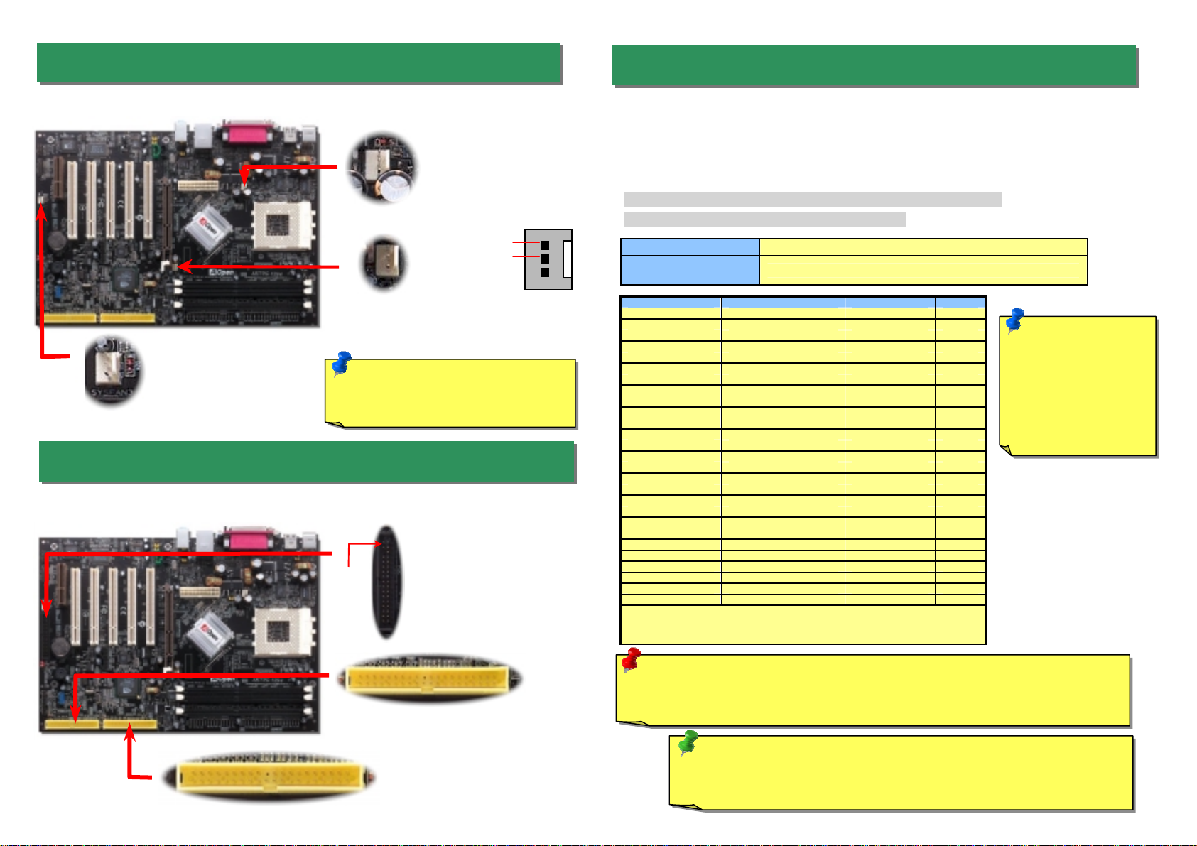
4. Connecting IDE & Floppy Connectors
3. Installing CPU & Housing Fan
Note: Some CPU fans do not have
sensor pin, so that they cannot
su
pp
ort fan monitorin
g
.
SYSFAN2 Connector
CPUFAN1 Connector
Full-range Adjustable CPU Core Voltage
This motherboard supports CPU VID function. The CPU core voltage will be automatically
detected and the range is from 1.1V to 1.85V. It is not necessary to set CPU Core Voltage.
Setting CPU Frequency
This motherboard is CPU jumper-less design, you can set CPU frequency through the
BIOS setup, and no jumpers or switches are needed.
BIOS Setup > Frequency / Voltage Control > CPU Speed Setup
Core Frequency = CPU FSB Clock * CPU Ratio
CPU Ratio From 5.5x to 16x step 0.5x
CPU FSB (Adjustment
manually) FSB = 100MHz-200MHz by 1MHz Stepping CPU Overclocking
CPU CPU Core Frequency EV6 Bus Clock Ratio
Athlon 1G 1GHz 200MHz 10.0x
Athlon 1.1G 1.1GHz 200MHz 11.0x
Athlon 1.2G 1.2GHz 200MHz 12.0x
Athlon 1.3G 1.3GHz 200MHz 13.0x
Athlon 1G 1GHz 266MHz 7.5x
Athlon 1.13G 1.13GHz 266MHz 8.5x
Athlon 1.2G 1.2GHz 266MHz 9.0x
Athlon 1.33G 1.33GHz 266MHz 10.0x
Athlon 1.4G 1.4GHz 266MHz 10.5x
AthlonXP 1500+ 1.3GHz 266MHz 10.0x
AthlonXP 1600+ 1.4GHz 266MHz 10.5x
AthlonXP 1700+ 1.46GHz 266MHz 11.0x
AthlonXP 1800+ 1.53GHz 266MHz 11.5x
AthlonXP 1900+ 1.6GHz 266MHz 12.0x
AthlonXP 2000+ 1.667GHz 266MHz 12.5x
AthlonXP 2100+ 1.73GHz 266MHz 13x
AthlonXP 2200+ 1.80GHz 266MHz 13.5x
AthlonXP 2400+ 2.0GHz 266MHz 15x
AthlonXP 2600+ 2.13GHz 266MHz 16x
AthlonXP 2700+ 2.16GHz 333MHz 13x
AthlonXP 2800+ 2.25GHz 333MHz 13.5x
Duron 800 800MHz 200MHz 8.0x
Duron 850 850MHz 200MHz 8.5x
Duron 900 900MHz 200MHz 9.0x
Duron 950 950MHz 200MHz 9.5x
Duron 1G 1GHz 200MHz 10.0x
Duron 1.1G 1.1GHz 200MHz 11.0x
Note: With CPU speed changing rapidly, there might be fastest CPU on the
market by the time you received this installation guide. This table is kindly for
your references only.
Tip: If your system hangs or fails to boot because of overclocking, simply use
<Home> key to restore the default setting or you can wait the AOpen “Watch Dog
Timer” reset the system in five seconds and system will auto-detect hardware again.
Warning: nForce2-ST/G/GT chipsets support 166MHz FSB (with performance reaches
maximum 333MHz EV6 system bus) and 66MHz AGP clock, higher clock setting may cause
serious system damage.
SYSFAN3 Connector
GND
+12
V
SENSO
R
Connect 34-pin floppy cable and 40-pin IDE cable to floppy connector FDC connector. Be
careful of the pin1 orientation. Wrong orientation may cause system damage.
Pin 1 FDD Connector
IDE 2
(Secondary)
IDE 1
(Primary)
Note: You have to
adjust CPU FSB in
BIOS after installing
CPU; otherwise CPU
will run at default
speed of CPU FSB
value.

7. Support USB2.0 Connector
6. Memory & AGP Voltage Adjustment
With our considerate design, you can adjust memory and AGP voltage in BIOS. The
memory voltage range is from 2.5V to 2.65V and the AGP voltage is from 1.5V to 1.6V.
This motherboard provides six USB connectors to connect USB devices, such as mouse,
keyboard, modem, printer, etc. There are four connectors on the back panel. You can use
proper cables to connect the Front USB connector to USB modules or front panel o
f
chassis.
9. IEEE 1394 Connectors (AK79D-1394 & AK79G-1394)
With IEEE1394 MAC Embedded in nForce2-GT/ST (with AGERE FW802A), the IEEE 1394
provides data transfer rate up to 400Mb/s, and USB just has 12Mbps. Hence, the IEEE 1394
interface can connect with the devices that need high data transferring performance, such as
digital camera, scanner or others IEEE 1394 devices. Please use the proper cable to connec
t
with devices.
Pin 1
Pi
n
1
KEY
1394_PWR
TPB+
GND
TPA+
Shielding GND
1394_PW
R
TPB-
GND
TPA- 2 1
10 9
Warning: Please be noted that
Hot-Plug in is not allowed on
IEEE 1394 header, because it will
burn the IC of the controller and
damage the motherboard.
+5V
SBD3-
SBD3+
GND
NC
+5V
SBD2-
SBD2+
GND
KEY
1
Note: You will have to take
your own risk to adjust those
voltages.
2nd USB Connector
8. Memory Module (128-Bit DDR Dual Channel)
In the past, we used to have 64-bit memory bandwidth for memory access. No matter how
many memory modules have been installed, though capacity added, the speed of access
remains the same. With 128-bit dual channel introduced, it doubles the memory bandwidth
up to 5.4GB in advanced 128-bit mode. This motherboard supports DDR400/333/266 with
Maximum capacity up to 3GB (When enabling VGA onboard, memory can run max. up to
333MHz)
128-bit DDR Dual Channel
Memory module

10. Connecting Front Panel Connector
11. Connecting Front Audio Connector
If the housing has been designed with an audio port on the front panel, you’ll be able to
connect onboard audio to front panel through this connector. By the way, please remove
5-6 and 9-10 jumper caps from the Front Audio Connector before connecting the cable.
Please do not remove these 5-6 and 9-10 yellow jumper caps if there’s no audio port on
the front panel.
A
ttach the power LED, speaker, and reset switch connector
s
to the corresponding pins. If you enable “Suspend Mode
”
item in BIOS Setup, the ACPI & Power LED will kee
p
flashing while the system is in suspend mode.
Locate the power switch cable from your ATX housing. It is
2-pin female connector from the housing front panel. Plug
this connector to the soft-power switch connector marked
SPWR.
Pin 1
12. S/PDIF Connector (AK79D-1394, AK79G-1394)
S/PDIF (Sony/Philips Digital Interface) is a newest audio transfer file format, which provides
impressive audio quality through optical fiber and allows you to enjoy digital audio instead o
f
analog audio. Through a specific audio cable, you can connect the S/PDIF connector to othe
r
end of the S/PDIF audio module, which bears S/PDIF digital output. Normally there are two
S/PDIF outputs as shown, one for RCA connector, the most common one used for consume
r
audio products, and the other for optical connector with better audio quality. Same as outputs,
you can also connect RCA or optical audio products to input connectors on the module and
have the voice or music come out from your computer. However, you must have a S/PDIF
supported speaker/amplifier/decoder with S/PDIF digital input/output to connect to the S/PDIF
digital input/output to make the most out of this function.
Pin 1
S/PDIF Module
(User Upgrade Optional)
S/PDIF
Cable
S/PDIF OUT
S/PDIF IN
(
RCA
)
S/PDIF IN
(Optical)
S/PDIF OU
T
13. Super 5.1 Channel Audio Effects
This motherboard comes with an ALC650 CODEC, which supports high quality of 5.1
Channel audio effects, bringing you a brand new audio experience. On the strength of the
innovative design of ALC650, you're able to use standard line-jacks for surround audio outpu
t
without connecting any external module. To apply this function, you have to install the audio
driver in the Bonus Pack CD as well as an audio application supporting 5.1 Channel. Picture
bellow represents the standard location of all speakers in 5.1Channel sound track. Please
connect the plug of your front speakers to the green “Speaker out” port, rear speakers’ plug
to the blue “Line in” port and both of the center and subwoofer speakers to the red “MIC in”
port.
1
SPWR
GND
ACPI LED-
GND
ACPILED
NC
ACPI_B
GND
RESET
GND
NC
NC
+5
V
IDE LED
IDE LED
+5
V
+5
V
GND
NC
SPEAKE
R
1
Speaker
IDE LED
SPWR
ACPI & PWR
LED
Reset
ACPI LED
(
Blue
)
1 AUD_GND
AUD_VCC
AUD_RET_R
KEY
AUD_RET_L
AUD_MIC
AUD_MIC_BIAS
AUD_FPOUT_R
NC
AUD_FPOUT_L
5
1
SPDIFIN
GND
SPDIFOUT
NC
+5V
This manual suits for next models
3
Table of contents
Other AOpen Motherboard manuals

AOpen
AOpen AX4T II Setup guide

AOpen
AOpen AX45-533 Max Setup guide

AOpen
AOpen MX4SGI-4DN Setup guide

AOpen
AOpen i915Ga-EFRII User manual

AOpen
AOpen AK86-L Setup guide

AOpen
AOpen MX4B Datasheet

AOpen
AOpen AX34-U Datasheet

AOpen
AOpen AX4GEFM User manual

AOpen
AOpen DX34 Plus User manual

AOpen
AOpen MoDT i965GMt-LA Instruction manual

AOpen
AOpen AK77-600 Max User manual

AOpen
AOpen AK33 M Setup guide

AOpen
AOpen MX3W-V User manual

AOpen
AOpen AX4C Max II Setup guide

AOpen
AOpen i855GMEm-LFS User manual

AOpen
AOpen MX 36 LE-U Setup guide

AOpen
AOpen MK33M(A) Datasheet

AOpen
AOpen AX3S Pro-U Datasheet

AOpen
AOpen MX33 Datasheet

AOpen
AOpen MK77-333 Datasheet