AOpen AX4B-133 Datasheet

PS/2 Mouse
Connector SPP/EPP/ECP Parallel Port MIDI/Game Port
MIC-In
Line-In
Speaker Out
PS/2 Keyboard
Connector USB Port COM 1 Port COM 2 Port
FAN3 Connecto
r
JP15 & 16 Dr. Voice Language
Select Jumpe
r
CD-IN Connecto
r
CNR Expansion Slot
IrDA Connecto
r
Front Panel Connecto
r
FDD Connecto
r
Supports 2
nd
USB Connecto
r
JP14 CMOS Clear Jumpe
r
4Mbit Flash ROM
Resettable Fuse
478-pin CPU socket with Voltage and
Frequency Auto-detection that supports
Intel
®
Pentium
®
4 1.4~2.4GHz+ CPU
AGP 4x Expansion Slot
(for 1.5V AGP card)
32-bit PCI Expansion Slot x5
CPU Fan Connector with H/W
Monitoring Function
184-pin DIMM Socket x3 supports
PC-200/266 DDR SDRAM
maximum up to 2 GB
Intel
®
845 chipset (Brookdale)
2200
μ
F Low ESR Capacitors
ATX Power Connector
AUX-IN Connecto
r
4-pin 12V. ATX Power Connector
Dr. LED Connecto
r
JP30 Die Hard BIOS
Select jumpe
r
(Upgrade optional)
RealTek ALC650 5.1 AC97 CODEC
Chassis Intrusion Connecto
r
Front Audio Connecto
r
Di
e
H
ar
d
BIOS
(Upgrade optional)
WOL Connecto
r
WOM Connecto
r
JP28 Keyboard/Mouse Wakeup
Enable/Disable Jumper
Promise ATA/133 IDE Connector x2
FAN2 Connector
JP2 Jumper (speaker)
JP1 Jumper (Buzzer)
S/PDIF Connecto
r
JP35 ATA/133
Enable/Disable Select Jumpe
r
ATA/66/100 IDE Connector x2

This motherboard comes with a 20-pin and 4-pin ATX power connector as shown below. Make sure you plug
in the right direction. We strongly recommend you to insert the 4-pin connector before connecting the 20-pin
connector.
Normal
(
default
)
1
Clear CMOS
1
1. JP14 Clear CMOS
Everything you need to boot this
motherboard is included in this
Easy Installation Guide. For more
information, a complete Online
User's Manual can be found in the
Bonus Pack CD Disc. Thanks for
the help of saving our earth.
PART NO: 49.89R03.E01 DOC. NO: AX4B133-EG-E0201A
You can clear CMOS to restore system default setting. To
clear the CMOS, follow the procedure below.
1. Turn off the system and unplug theAC power.
2. RemoveATX power cable from connector PWR2.
3. Locate JP14 and short pins 2-3 for a few seconds.
4. Return JP14 to its normal setting by shorting pin 1 & pin 2.
5. ConnectATX power cable back to connector PWR2.
Tip: When should I Clear CMOS?
1. Boot fail because of overclocking…
2. Forget password…
3. Troubleshooting…
2. Connecting ATX Power Connector
This Motherboard x1
This Easy Installation Guide x1
User Manual x 1
40-wire IDE Cable x1
80-wire IDE Cable x1
Floppy Disk Drive Cable x1
Retention Module x1
Bonus Pack CD x1
NORTON AntiVirus CD x1
Pin 1
Ground
12V
12V
Ground
COM
COM
-5
V
+5
V
+5
V
+12
V
5VSB
PO-O
K
COM
+5
V
COM
PS-ON
COM
-12V
+3.3V
+3.3V
+3.3V
COM
+5V
COM

1. Pull up the CPU socket lever and up to
90-degree angle.
2. Locate Pin 1 in the socket and look fo
r
a (golden) cut edge on the CPU uppe
r
interface. Match Pin 1 and cut edge.
Then insert the CPU into the socket.
3. Press down the CPU socket lever and
finish CPU installation.
Plug in the CPU fan cable to the 3-pin CPU FAN connector. If you have chassis fan, you
can also plug it on System Fan (FAN2) or FAN3 (AUX Fan) connector.
CPU Ratio 8x, 9x, 10x… 21x, 22x, 23x, 24x
CPU FSB 100~248MHz
CPU CPU Core
Frequency
FSB Clock System
Bus
Ratio
Pentium 4 1.4G 1400MHz 100MHz 400MHz 14x
Pentium 4 1.5G 1500MHz 100MHz 400MHz 15x
Pentium 4 1.6G 1600MHz 100MHz 400MHz 16x
Pentium 4 1.7G 1700MHz 100MHz 400MHz 17x
Pentium 4 1.8G 1800MHz 100MHz 400MHz 18x
Pentium 4 1.9G 1900MHz 100MHz 400MHz 19x
Pentium 4 2G 2000MHz 100MHz 400MHz 20x
Pentium 4 2.2G 2200MHz 100MHz 400MHz 22x
Pentium 4 2.4G 2400MHz 100MHz 400MHz 24x
5. Setting CPU Voltage & Frequency
Setting CPU Core Voltage
This motherboard supports CPU VID function. The CPU core voltage will be automaticall
y
detected and the range is from 1.05V to 1.825V. It is not necessary to set CPU core
voltage.
Setting CPU Frequency
This motherboard is CPU jumper-less design, you can set CPU frequency through the
BIOS setup, and no jumpers or switches are needed.
BIOS Setup > Frequency / Voltage Control > CPU Speed Setting
Core Frequency = CPU FSB Clock * CPU Ratio
3. Installing Processor
Note: If you do not match the CPU
socket Pin 1 and CPU cut edge well, it
may damage the CPU.
CPU socket lever
CPU Pin 1 and cut edge
Note: Some CPU fans do not have
sensor pin so they cannot support fan
monitoring.
CPU Fan Connector
Warning: Intel
®
845 chipset supports
maximum 400MHz
(100MHz*4) system
bus and 66MHz
A
GP clock; higher
clock setting may
cause serious
system damage.
4. Installing CPU & System Fan
FAN2 Connector
This socket supports Micro-FC-PGA2 package CPU, which is the latest CPU package
developed by Intel. Other forms of CPU package are impossible to be fitted in.
GND
+12V
SENSOR
FAN3 Connector
GND
+12V
SENSOR
GND
+12V
SENSOR
USBPWR0
USB_FP_P0-
USB_FP_P0+
GND
KEY
USBPWR0
USB_FP_P1-
USB_FP_P1+
GND
USB_FP_OC0
1 2
6. Support 2
nd
USB Port
This motherboard provides four USB connectors to connect USB devices, such as mouse,
keyboard, modem, printer, etc. There are two connectors on the PC99 back panel. You
can use proper cable to connect the other USB connector to the back panel or front panel
of chassis.
USB2 Connector
Pin 1

Secondary
Master (3rd)
Secondary
Slave (4th)
Pin 1
Primary
Slave (2nd) Primary
Master (1st)
9. Connecting IDE and Floppy Cables
10. Connecting Front Panel Cable
8. Connect IrDA Connector
The IrDA connector can be configured to support wireless infrared module, with this
module and application software such as Laplink or Windows 95 Direct Cable
Connection, the user can transfer files to or from laptops, notebooks, PDA devices and
printers. This connector supports HPSIR (115.2Kbps, 2 meters) andASK-IR (56Kbps).
Install the infrared module onto the IrDA connector and enable the infrared function from
BIOS Setup, UART mode select, make sure to have the correct orientation when you plug
in the IrDAconnector.
Connect 34-pin floppy cable and 40-pin, 80-wire IDE cable to floppy connector FDC and
IDE connector. Be careful of the pin1 orientation. Wrong orientation may cause system
damage.
Pin 1
ATA /66/100
IDE Connector
Attach the power LED, speaker, and reset switch connectors to
the corresponding pins. If you enable “Suspend Mode” item in
BIOS Setup, the ACPI & Power LED will keep flashing while the
system is in suspend mode.
Locate the power switch cable from your ATX housing. It is
2-pin female connector from the housing front panel. Plug this
connector to the soft-power switch connector marked SPWR.
FDD Connector
IDE 1 (Primary)
IDE 2 (Secondary)
IrDA Connector
Pin 1
1
Speaker
IDE LED
SPWR
A
CPI & PWR
LED
Reset
1
5VSB
SPWR
ACPI LED-
GND
ACPILED
NC
NC
GND
RESET
GND
GND
Keylock
+5V
IDE LED
IDE LED
+5V
+5V
GND
NC
SPEAKER
7. Front Audio Connector
If the housing has been designed with an audio port on the front panel, you’ll be able to
connect onboard audio to front panel through this connector. By the way, please remove
the jumper cap from the Front Audio Connector before you connect the cable. Do no
t
remove this yellow jumper cap if housing without an audio port on the front panel.
Pin 1
AUD_MIC
NC
AUD_FPOUT_R
NC
AUD_FROUT_L
AUD_GND
AUD_VCC
AUD_RET_R
KEY
NC
9 10
1 2
IDE 3 (Primary)
IDE 4 (Secondary)
Promise /133
IDE Connector
IR_TX
+5V
NC
IR_RX
GND
KEY
1

Caution: By updating your motherboard, you are taking a risk
of BIOS flash failure. If your motherboard is working stable,
and there are no major bugs that had been fixed by a latter
BIOS revision, we recommend that you DO NOT try to upgrade
your BIOS.
If you intent on upgrading, PLEASE BE SURE to get the right
BIOS revision for the right motherboard model to avoid any
p
ossibility failure.
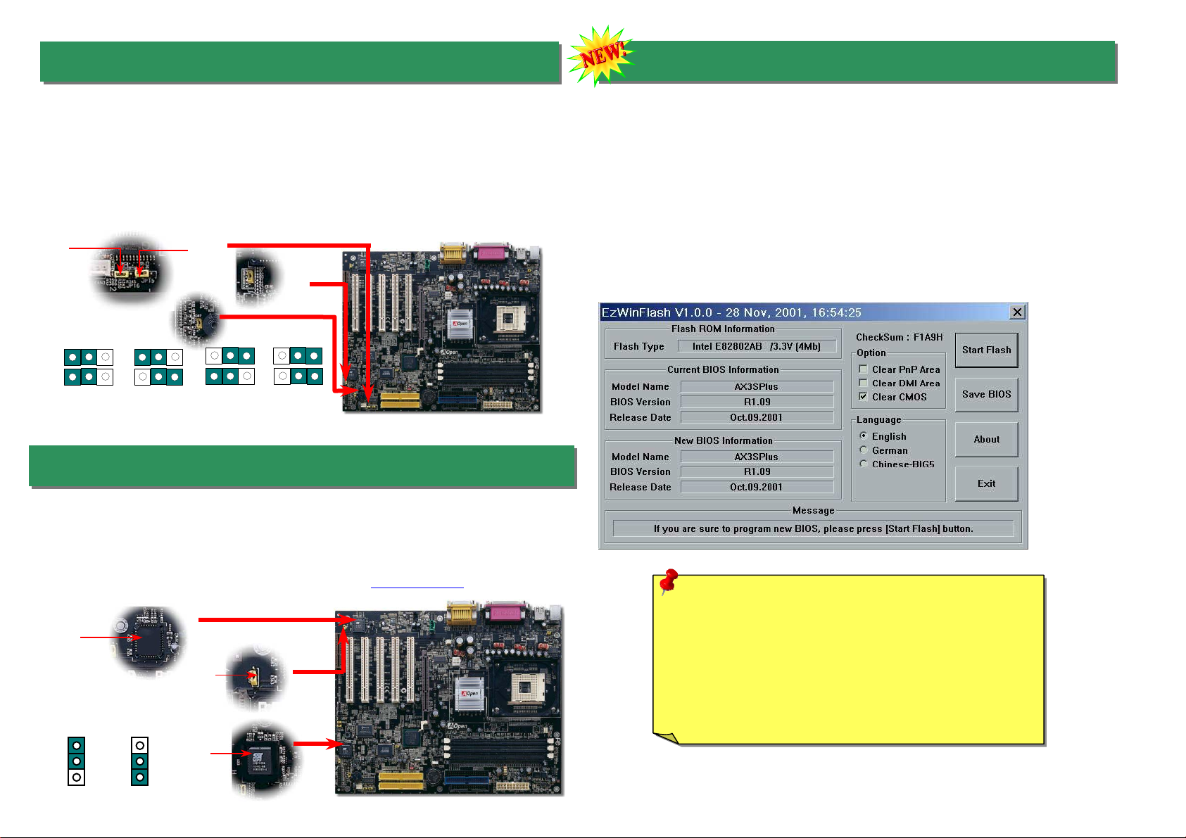
12. Die-Hard BIOS (Upgrade optional)
11. Dr. Voice
The Dr. Voice is a great feature of AX4B Pro motherboard, which can identifies what kind
of problems had occurred in the operating system. It can even clearly “tell” whether there
is a component issue or an installed issue, such as CPU, memory module, VGA, PCI
add-on card, FDD, HDD or keyboard by voice. The Dr. Voice provides four kinds of
language versions, English, German, Japanese and Chinese for your choosing. You
can select preferred language version by JP15 & JP16 jumpers. However, if you want to
disable this function, you may also set JP1 and JP2 to pin 2-3 to disable to buzzer and
speaker from making out voices respectively.
JP15
Pin 1
JP16
Pin 1
Recently, many viruses have been found that they may destroy bios code and data area.
Therefore, this motherboard implements a very effective hardware protection method that does
not involve any software or BIOS coding, hence it is 100% virus free. You may restore the
originally mounted BIOS with 2
nd
BIOS ROM by setting JP30 to pin 2-3 if it fails to act normally.
This motherboard comes with one BIOS ROM, you may contact our local distributor or reseller
for purchasing the extra BIOS ROM. Please visit our website: www.aopen.com for details.
1
normal
1
rescue
BIOS
ROM
Rescue
ROM
JP30
JP2
JP1
JP15
Pin 1
JP16
Pin 1 English
(Default) Chinese Japanese
German
13. BIOS Upgrade under Windows environment
With outstanding R&D ability of AOpen, we now bring you a whole new BIOS Flash wizard
---- EZWinFlash. With an eye to users convenience, EZWinFlash combines the BIOS
binary code and flash module together, so the only thing you have to do is just clicking on
the utility you downloaded from web and let it helps you complete the flash process
automatically. EZWinFlash detects your motherboard and checks the BIOS version
cleverly to prevent your system from any possible failure. Moreover, EZWinFlash has been
taken into consideration to go with any windows platform you might be using, no matter i
f
you’re using Windows 95/98, 98SE/ME, NT4.0/2000, or even the latest Windows XP.
In the meanwhile, in order to provide a much more user-friendly operating environment,
AOpen EZWinFlash is natively designed to have multi-language function to provide easier
way for users’ usage in changing BIOS setting.
Table of contents
Other AOpen Motherboard manuals

AOpen
AOpen AX64 Setup guide

AOpen
AOpen AX4S-U User manual

AOpen
AOpen MX46-533 Max Setup guide

AOpen
AOpen AK89 MAX Datasheet

AOpen
AOpen AP5V User manual

AOpen
AOpen i915Ga-HFS User manual

AOpen
AOpen MX34 Datasheet

AOpen
AOpen i855GMEm-LFS User manual

AOpen
AOpen i915Gm-IE User manual

AOpen
AOpen AX4SG Max II User manual

AOpen
AOpen AX4BR-U User manual

AOpen
AOpen i915Ga-HFS Datasheet

AOpen
AOpen AX4SG WLAN User manual

AOpen
AOpen AX34-U Datasheet

AOpen
AOpen AX3S Max User manual

AOpen
AOpen AX4PE Max Setup guide

AOpen
AOpen AXPS-U User manual

AOpen
AOpen MX36LE-U Datasheet

AOpen
AOpen MX36LE-N User manual

AOpen
AOpen MX4LR-GN Datasheet