IEEE 1394 Connectors
With IEEE1394 Chip on board (AGERE 1394), having its data transfer rate up to
400Mb/s, this interface can connect to devices that require high data transferring
performance such as digital camera, scanner or others IEEE 1394 devices. Please
use appropriate cables to connect IEEE1394 devices.
Pin 1
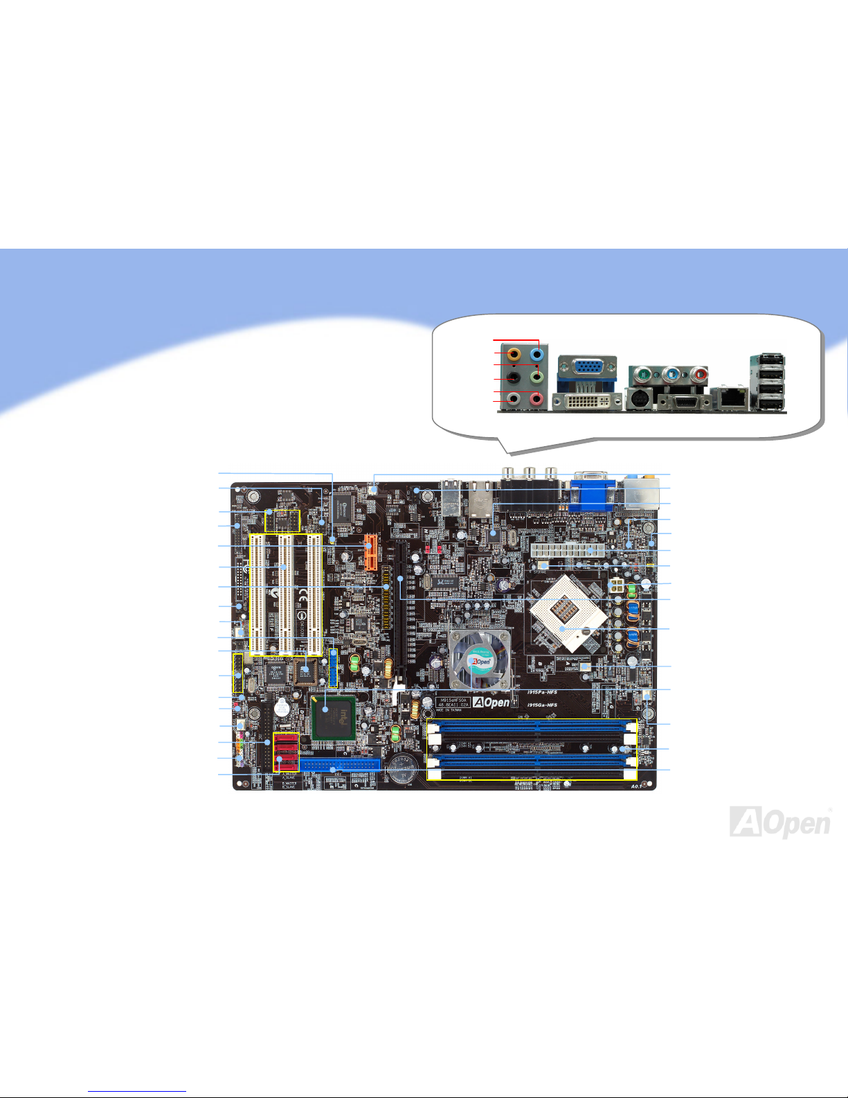
Gigabit LAN onboard
On the strength of Marvell Gigabit LAN chip on board, the motherboard provides
10/100/1000Mbps Ethernet for home and office use. The Ethernet RJ45 connector
is located on top of USB connectors. The right hand side LED indicates link mode,
it lights in yellow whenever linking to network. The left hand side LED indicates the
transfer mode and it lights in green when data is transferring in 100Mbps (never
lights while in 10Mbps), but lights in orange when transferring in Gigabit’s mode.
To enable or disable this function, you may simply adjust it through BIOS.
Transferring (Left)
Green 100Mbps
Orange Gigabit mode
Linking (Right)
Yellow
Front Audio Connectors
If the housing has been designed with an audio port on the front panel, you’ll be
able to connect onboard audio to front panel through this connector. By the way,
please remove 5-6 and 9-10 jumper caps from the Front Audio Connector before
connecting the cable. Please do not remove these 5-6 and 9-10 yellow jumper
caps if there’s no audio port on the front panel.
Serial ATA Connectors
To connect a serial ATA disk, you have to have a 7-pin serial ATA cable. Connect
two ends of the serial ATA cable to the serial ATA header on the motherboard and
the disk. Like every other traditional disk, you also have to connect a power cable.
Please be noted that it is a jumper free implement; you don’t need to set jumpers
to define a master or slave disk. When serial ATA hard disks are installed on serial
ATA ports, the one connected on SATA1 will be set as the first boot device
automatically. Please note that it doesn’t support Hot-Plug in function.
Pin 1