AOpen MX4GVR Datasheet

Chassis Intrusion Connecto
r
CD-IN Connecto
r
Front Audio Connecto
r
IrDA Connecto
r
Front Panel Connecto
r
FDD Connecto
r
USB2.0 Connecto
r
JP14 CMOS Clear Jumpe
r
A
U
X
-IN Connecto
r
Resetable Fuse
478-pin CPU socket
(Willamette/Northwood) with Voltage and
Frequency Auto-detection that supports
Intel®Pentium®4 1.4~2.4GHz+ CPU
A
DD Slot
(For ADD card only)
32-bit PCI Expansion Slot x3
184-pin DIMMx2 supports DDR266/200
DDR SDRAM maximum u
p
to 2GB
Intel 845GV Chi
p
set
Low ESR Ca
p
acitors
A
TX Power Connecto
r
ATA 33/66/100 IDE Connecto
r
4-pin 12V. ATX Power Connecto
r
RealTek RTL8100BL
PS/2 Mouse
Connector SPP/EPP/ECP Parallel Port
USB2.0
Ports
RJ45 10/100
LAN Jack
PS/2 Keyboard
Connector USB2.0 Port
COM 1 Port VGA Port
A
C’97 CODEC
SYSFAN3 Connecto
r
CPUFAN1 Connecto
r
S/PDIF Connecto
r
SYSFAN2 Connecto
r
4Mb Flash ROM BIOS
WOL Connecto
r
COM2 Connecto
r
JP28 USB/Keyboard/Mouse Wakeup Jumpe
r
JP27 USBLAN Wakeu
p
Jum
p
e
r
CNR Connecto
r
Line-In
Speaker
Out
MIC-In
BOOT LED
STBY LED
A
Open reserves the right to revise all the specifications and information contained in this documentation, which are subject to change without notice.

2nd USB Channel 1st USB Channel
1. JP14 Clear CMOS
Everything you need to boot this
motherboard is included in this
Easy Installation Guide. For more
information, a complete Online
User's Manual can be found in the
Bonus Pack CD. Thanks for the
help of saving our earth.
PART NO: 49.8B411.E01 DOC. NO: MX4GVR-EG-E0208A
This motherboard provides USB and PS2 keyboard / mouse wake-up function. You can use JP27 / JP28 to
enable or disable this function, which could resume your system from suspend mode with keyboard o
r
mouse installed. JP28 controls 1st USB channel, and JP27 controls 2nd USB channel. The factory defaul
t
setting is set to “Disable”(1-2), and you may enable this function by setting the jumper to 2-3.
You can clear CMOS to restore system default setting. To
clear the CMOS, follow the procedure below.
1. Turn off the system and unplug the AC power.
2. Remove ATX power cable from connector PWR2.
3. Locate JP14 and short pins 2-3 for a few seconds.
4. Return JP14 to its normal setting by shorting pin 1 & pin 2.
5. Connect ATX power cable back to connector PWR2.
Tip: When should I Clear CMOS?
1. Boot fail because of overclocking…
2. Forget password…
3. Troubleshooting…
This Easy Installation Guide x1
80-wire IDE Cable x1
Floppy Disk Drive Cable x1
Registration Card x1
Bonus Pack CD x1
S/PDIF Cable x 1 (User Upgrade Optional)
Retention Module x1
I/O Shield x1
Pin 1
2. JP27/28 Keyboard/Mouse Wakeup Jumper
Normal
(
default
)
1
Clear CMOS
1
JP27
Enable
Disable
(Default)
1JP28
EnableDisable
(Default)
1
Pin 1

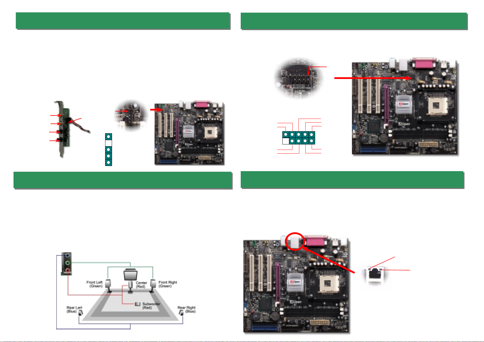
Plug in the CPU fan cable to the 3-pin CPUFAN1 connector. If you have chassis fan, you
can also plug it in SYSFAN2 or SYSFAN3 connector.
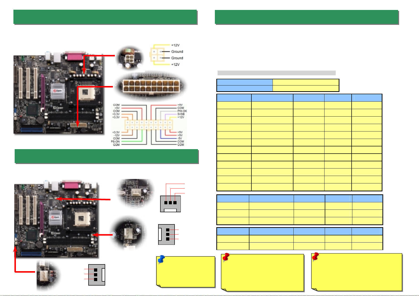
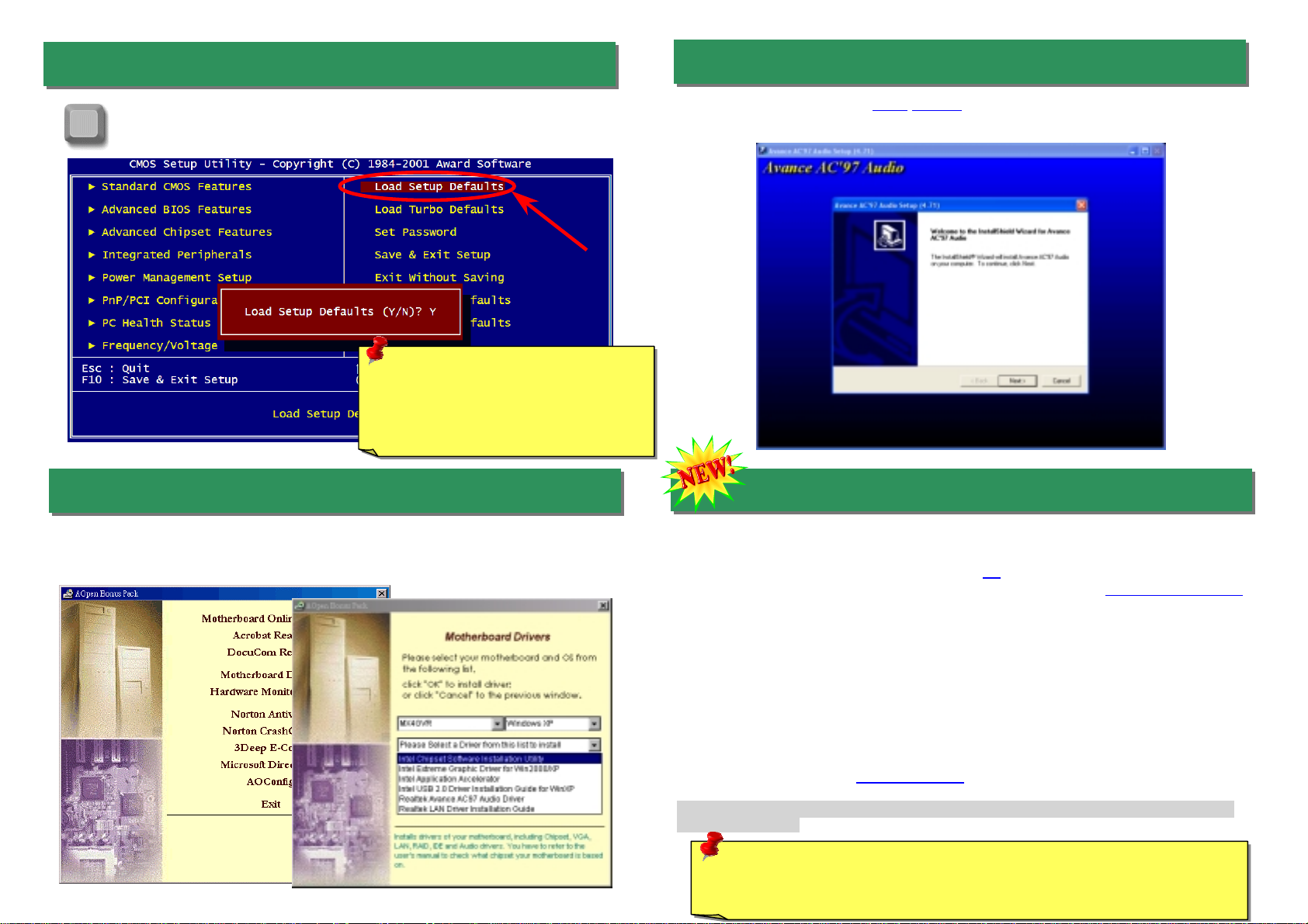
This motherboard comes with a 20-pin and 4-pin ATX power connector as shown below.
Make sure you plug in the right direction. We strongly recommend you to insert the 4-pin
connector before connecting the 20-pin connector.
CPU Ratio 8x, 10x… 21x, 22x, 23x, 24x
CPU FSB (By BIOS table) 100 and 133MHz.
Northwood CPU CPU Core Frequency FSB Clock System Bus Ratio
Pentium 4 1.6G 1600MHz 100MHz 400MHz 16x
Pentium 4 1.6G 1600MHz 133MHz 533MHz 12x
Pentium 4 1.7G 1700MHz 133MHz 533MHz 13x
Pentium 4 1.8G 1800MHz 100MHz 400MHz 18x
Pentium 4 2.0G 2000MHz 100MHz 400MHz 20x
Pentium 4 2.2G 2200MHz 100MHz 400MHz 22x
Pentium 4 2.26G 2260MHz 133MHz 533MHz 17x
Pentium 4 2.4G 2400MHz 100MHz 400MHz 24x
Pentium 4 2.4G 2400MHz 133MHz 533MHz 18x
Pentium 4 2.53G 2530MHz 133MHz 533MHz 19x
Pentium 4 2.66G 2660MHz 133MHz 533MHz 20x
Pentium 4 2.80G 2800MHz 133MHz 533MHz 21x
Willamette CPU CPU Core Frequency FSB Clock System Bus Ratio
Pentium 4 1.8G 1800MHz 100MHz 400MHz 18x
Pentium 4 1.9G 1900MHz 100MHz 400MHz 19x
Pentium 4 2.0G 2000MHz 100MHz 400MHz 20x
Celeron CPU CPU Core Frequency FSB Clock System Bus Ratio
1.7G 1700MHz 100MHz 400MHz 17x
1.8G 1800MHz 100MHz 400MHz 18x
5. Setting CPU Voltage & Frequency
Setting CPU Core Voltage
This motherboard supports CPU VID function. The CPU core voltage will be automaticall
y
detected.
Setting CPU Frequency
This motherboard is CPU jumper-less design, you can set CPU frequency through the
BIOS setup, and no jumpers or switches are needed. The default setting is "table select
mode". You can adjust the FSB from "CPU Host/SDRAM/PCI Clock" for overclocking.
BIOS Setup > Frequency / Voltage Control > CPU Speed Setup
3. ATX Power Connectors
Note: Some CPU fans
do not have sensor pin
so they cannot support
fan monitoring.
CPUFAN1 Connector
Warning: Intel 845GV supports
maximum 533MHz system bus and
66MHz AGP clock; higher clock
setting may cause serious system
damage.
4. Installing CPU & System Fan
SYSFAN3 Connector
SYSFAN2 Connector
GND
+12V
SENSOR
Note: Since the latest processor,
Northwood, would detect the clock
ratio automatically, you may not
be able to adjust the clock ratio in
BIOS manuall
y
.
GND
+12V
SENSOR

USB2.0 Connector
Front Audio Connector
9. Connecting Front Panel Cable
6. 2nd USB2.0 Connectors
This motherboard provides six USB connectors to link USB devices, such as mouse,
keyboard, modem, printer, etc. There are four ports on the PC99 back panel. You can use
proper cable to connect other USB connectors to the back panel or front panel of chassis.
Pin1
7. Front Audio Connector
If the housing has been designed with an audio port on the front panel, you’ll be able to
connect onboard audio to front panel through this connector. By the way, please remove
5-6 and 9-10 jumper caps from the Front Audio Connector before connecting the cable.
Please do not remove these 5-6 and 9-10 yellow jumper caps if there’s no audio port on
the front panel.
Pin 1
A
UD_FPOUT_L
HP_ON
A
UD_RET_
R
A
UD_VCC
A
UD_GND2
110
9
A
UD_MIC
A
UD_MIC_BIAS
A
UD_FPOUT_
R
KE
Y
AUD_RET_L
The IrDA connector can be configured to support wireless infrared module, with this module
and application software such as Laplink or Windows 95 Direct Cable Connection, the use
r
can transfer files to or from laptops, notebooks, PDA devices and printers. This connecto
r
supports HPSIR (115.2Kbps, 2 meters) and ASK-IR (56Kbps).
Install the infrared module onto the IrDA connector and enable the infrared function from
BIOS Setup, UART Mode, make sure to have the correct orientation when you plug in the
IrDA connector.
8. IrDA Connector
Pi
n
1
1
KEY
GND
IR_RX
NC
+5V
IR_TX
IrDA Connector
USBPWR0
USB_FP_P0-
USB_FP_P0+
GND
KE
Y
USBPWR0
USB_FP_P1-
USB_FP_P1+
GND
USB_FP_OC0
1 2
A
ttach the power LED, speaker, and reset switch connectors to
the corresponding pins. If you enable “Suspend Mode” item in
BIOS Setup, the ACPI & Power LED will keep flashing while the
system is in suspend mode.
Locate the power switch cable from your ATX housing. It is
2-pin female connector from the housing front panel. Plug this
connector to the soft-power switch connector marked SPWR.
1
Speaker
IDE LED
SPWR
A
CPI & PWR
LED
Reset
A
CPI LED (BLUE)
1
SPWR
GND
ACPI LED-
GND
ACPILED
NC
ACPI_B
GND
RESET
GND
NC
NC
+5
V
IDE LED
IDE LED
+5
V
+5
V
GND
NC
SPEAKE
R

On the strength of RealTek RTL8100BL LAN controller on board, which is a highly-integrated
Platform LAN Connect device, it provides 10/100M bps Ethernet for office and home use, the
Ethernet RJ45 connector is located on top of USB connectors. The green LED indicates the
link mode, it lights when linking to network and blinking when transferring data. The orange
LED indicates the transfer mode, and it lights when data is transferring in 100Mbps mode. To
enable or disable this function, you may simply adjust it through BIOS.
12. COM2 Connector
This motherboard provides two serial ports. One of them is on back panel connector, and the
other is on the upper middle of board. With proper cable, you can connect it to the back panel o
f
chassis.
13. Support 10/100 Mbps LAN Onboard
Pin 1
Orange/Speed
Green/ACT
10. S/PDIF (Sony/Philips Digital Interface) Connector
S/PDIF (Sony/Philips Digital Interface) is a newest audio transfer file format, which provides
impressive audio quality through optical fiber and allows you to enjoy digital audio instead
of analog audio. Through a specific audio cable, you can connect the S/PDIF connector to
other end of the S/PDIF audio module, which bears S/PDIF digital output. Normally there
are two S/PDIF outputs as shown, one for RCA connector, the most common one used fo
r
consumer audio products, and the other for optical connector with better audio quality.
Same as outputs, you can also connect RCA or optical audio products to input connectors
on the module and have the voice or music come out from your computer. However, you
must have a S/PDIF supported speaker/amplifier/decoder with S/PDIF digital input/output to
connect to the S/PDIF digital input/output to make the most out of this function.
Pin 1
S/PDIF Module
(User Upgrade Optional)
S/PDIF
Cable
S/PDIF OUT
S/PDIF IN
(RCA)
S/PDIF IN
(Optical)
S/PDIF OUT
11. Super 5.1 Channel Audio Effects
+5V
NC
S/PDIFOUT
GND
S/PDIFIN
1
This motherboard comes with an ALC650 CODEC, which supports high quality of 5.1
Channel audio effects, bringing you a brand new audio experience. On the strength of the
innovative design of ALC650, you're able to use standard line-jacks for surround audio outpu
t
without connecting any external module. To apply this function, you have to install the audio
driver in the Bonus Pack CD as well as an audio application supporting 5.1 Channel. Picture
bellow represents the standard location of all speakers in 5.1Channel sound track. Please
connect the plug of your front speakers to the green “Speaker out” port, rear speakers’ plug
to the blue “Line in” port and both of the center and subwoofer speakers to the red “MIC in”
port.
1
2
GND
SOUT
DOD#
RI#
RTS#
SIN
DTR#
DSR#
CTS#
COM2
C
onnecto
r
Other manuals for MX4GVR
1
Table of contents
Other AOpen Motherboard manuals

AOpen
AOpen s760GXm-SL User manual

AOpen
AOpen AX45H-8X Max Datasheet

AOpen
AOpen i855GMEm-LFS User manual

AOpen
AOpen AX4B-533 Tube Datasheet

AOpen
AOpen MX46 U2 Setup guide

AOpen
AOpen AX4R Plus Setup guide

AOpen
AOpen MX3W-E2 Setup guide

AOpen
AOpen AX4GR Setup guide

AOpen
AOpen AX4LR User manual

AOpen
AOpen DXPL-U Setup guide

AOpen
AOpen i945Ga-PLF User manual

AOpen
AOpen s661FXm-S User manual

AOpen
AOpen AX4SPE Max II Datasheet

AOpen
AOpen AX4GE Tube-G Setup guide

AOpen
AOpen MX4SGI-4DN2 User manual

AOpen
AOpen DX37PU-OL-E0112B User manual

AOpen
AOpen Fortress 9000 Setup guide

AOpen
AOpen AK33 M Datasheet

AOpen
AOpen AK73-1394 Setup guide

AOpen
AOpen MX4B-533 User manual