AOR AR2300 User manual

0
AR2300 BLACK-BOX RECEIVER
“I/Q SPECIAL EDITION”
OPERATING MANUAL
OCTOBER 1, 2021
AOR, LTD.
.aorja.com

1

1
INTRODUCTION
Thank you for purchasing the AR2300.
AR2300 is a high-end black-box type receiver ith ide band coverage bet een 40kHz and 3.15GHz. Some of its
outstanding features are:
1) Digital signal processing:
Input signals after the 45.05MHz IF are converted from analog to digital by a DSP processor. There is no AGC in
the analog processing unit, as all processing, including AGC, is done by DSP.
2) High-performance analog front-end:
Analog signal processing is performed by a computer simulated, high-performance distribution constant filter.
3) DDS local oscillator:
Instead of the conventional PLL method, the first local frequency is produced by direct digital synthesis. That
method allo s frequency s itching at high speed.
4) IF output:
An analog IF of 15MHz (+/-7.5MHz) band idth is output.
5) Digital I Q output:
A digital I/Q signal of 0.9MHz is output via a USB 2.0 interface.
6) High precision frequency reference:
0.01ppm frequency stability of the 10MHz internal master oscillator is achieved hen using the optional GPS
receiver unit.
7) FFT analyzer:
Thanks to the onboard FFT processor, 10MHz ide spectrum data can be output at high speed via serial.
8) Optional APCO25 Phase 1 digital voice demodulation
9) Video demodulation
By connecting and external TV monitor, it is possible to demodulate the signal of FM modulation security
cameras and analog TV broadcasts. When you connect the TV monitor, you can check the demodulated video.
Not compatible ith digital terrestrial television.
10) Simultaneous monitoring
2 band reception, offset reception, triple reception (restrictions apply).
11) SD card slot
You can record the received audio on SD, as ell as backing up receiver settings and memory data.
12) 12kHz analog I Q output
Allo s DRM broadcasts decoding via a PC and dedicated 3rd party soft are.
13) HF direct sampling
When receiving HF signals, the signals are converted directly to digital ithout entering the mixer. This allo s
very good linearity characteristics.
14) Control via LAN Internet with optional ARL2300 Ethernet Controller
Please read this operating manual carefully. This information ill allo you to enjoy maximum performance from
your receiver. Due to continuous developments of the receiver, firm are and soft are, e ackno ledge that there
might be some changes, errors or omissions.
We sincerely hope that the AR2300 ill be your monitoring companion for many years to come.

2
SAFETY PRECAUTIONS
DO NOT operate the receiver near unshielded electrical blasting caps or in an explosive atmosphere. This could cause
an explosion and death.
DO NOT operate the receiver ith a headset or other audio accessories at high volume levels. If you experience a
ringing in your ears, reduce the volume or discontinue use.
DO NOT directly apply AC po er to the DC socket on the receiver rear panel. This could cause a fire or damage the
receiver.
DO NOT apply more than 16 V to the DC socket on the receiver rear panel. This could cause a fire or damage the
receiver.
DO NOT reverse the DC po er cable polarity. This could cause a fire or damage the receiver.
DO NOT let metal, ire or other objects contact the inside of the receiver, or make incorrect contact ith connectors
on the rear panel. This could cause an electric shock or damage the receiver.
DO NOT operate or touch the receiver ith et hands. This could cause an electric shock or damage to the receiver.
Immediately turn OFF the receiver po er and remove the po er cable from the receiver if it emits an abnormal odor,
sound or smoke. Contact your AOR dealer or distributor for advice.
DO NOT put the receiver on an unstable place here the receiver may suddenly move or fall. This could cause an injury
or damage the receiver.
DO NOT operate the receiver during a lightning storm. It may result in an electric shock, cause a fire or damage the
receiver. Al ays disconnect the po er source and antenna before a storm.
DO NOT expose the receiver to rain, sno or any liquids.
DO NOT change the internal settings of the receiver. This could reduce receiver performance and / or damage the
receiver. The receiver arranty does not cover any problems caused by unauthorized internal adjustments.
DO NOT install or place the receiver in a place ithout adequate ventilation.
DO NOT use harsh solvents such as Benzine or alcohol hen cleaning, as they ill damage the receiver surfaces.
DO NOT leave the receiver in areas ith temperatures belo 0°C or above +50°C.
DO NOT place the receiver in excessively dusty environments. This could damage the receiver.
DO NOT place the receiver against alls or put anything on top of the receiver. This may overheat the receiver. The
receiver ill become hot hen operating the receiver continuously for long periods of time.
Turn OFF the receiver’s po er and / or disconnect the DC po er cable hen you ill not use the receiver for a long
period of time.
The AR2300 may receive its o n oscillated frequency, resulting in no reception or only noise reception including on the
spectrum displayed by control soft are, on some frequencies.

3
TABLE OF CONTENTS
1. Supplied items ........................................................................................................................... 1
2. Front rear panel description ...................................................................................................... 2
2.1. Front panel ................................................................................................................................. 2
2.2. Rear panel................................................................................................................................... 3
3. Preparing for PC control (Controlsoft: Full receiver control & memory management) ..................... 5
3.1. PC requirements ......................................................................................................................... 5
3.2. Connecting the receiver to the PC .............................................................................................. 5
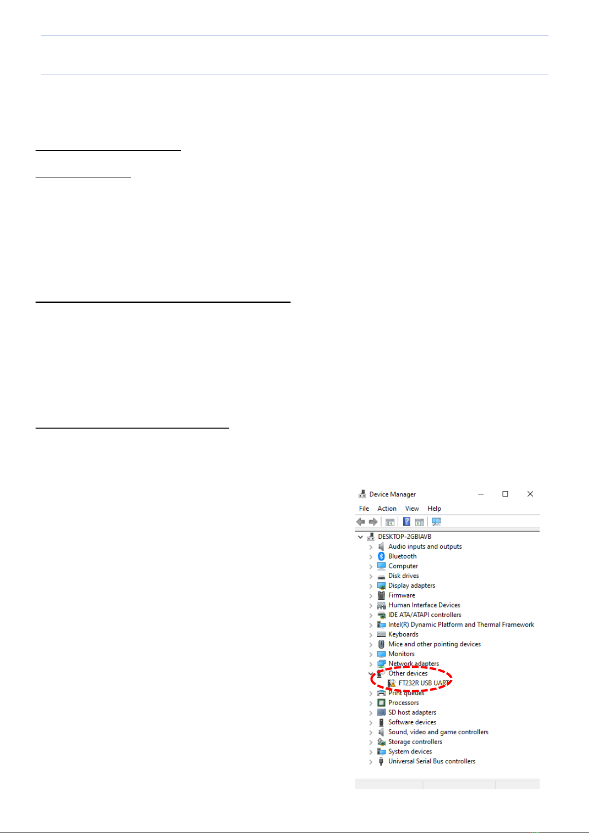
3.3. Installing the USB driver ............................................................................................................. 5
4. Control software operation ........................................................................................................ 7
4.1. Connecting po er ...................................................................................................................... 7
4.2. Po er on .................................................................................................................................... 7
4.3. Starting the control soft are ..................................................................................................... 7
4.4. Soft are indo s description ................................................................................................... 8
4.4.1 Main control indo description .............................................................................................. 9
4.4.2 Spectrum display description ................................................................................................... 10
4.4.3 Menu bar description ............................................................................................................... 10
4.4.4 Database indo description .................................................................................................. 13
4.4.5 Description of control indo s 1 and 2................................................................................... 14
4.4.6 Description of control indo s 3 and 4................................................................................... 15
4.4.7 Description of control indo 5 .............................................................................................. 16
4.4.8 Description of control indo 6 .............................................................................................. 17
5. AR2300 specifications ............................................................................................................... 18
Additions for the “I Q Special Edition”:
6. WINDOWS SOFTWARE ............................................................................................................. 19
6.1. AR-IQ-III (Receiver control, I/Q REC & playback) ...................................................................... 19
6.2. IQ for GNURadio (I/Q converter for use ith GNURadio on Windo s) ................................... 38
6.3. AR2300 Editing Soft are (Memory channel editor) ................................................................ 42
7. LINUX SOFTWARE ..................................................................................................................... 44
7.1. ARL2300 Local (Receiver control for Linux) .............................................................................. 44
7.2. REL (I/Q capture for Linux) ....................................................................................................... 49

1
1. SUPPLIED ITEMS
●
AR2300 receiver ___________________________ 1
●
IQ5001 I/Q output board (pre-installed)________ 1
●
AC po er adapter _________________________ 1
●
Printed user manual ________________________ 1
●
SD card __________________________________ 1
●
USB cable ________________________________ 2
●
USB license dongle ith soft are suite & drivers _ 1
A list of optional accessories is available at:
http:// .aorja.com/accessories/receiver_accessories.html
The full control command set pdf for system integrators can be do nloaded at:
http:// .aorja.com/support/manuals2/AR2300_command_list.html
AOR soft are and utilities are listed at:
http:// .aorja.com/support/soft are.html
A list of 3
rd
party soft are solutions is available at:
http:// .aorja.com/support/third_party_s .html

2
2. FRONT REAR PANEL DESCRIPTION
2.1. Front panel
①
Po er s itch
If you need to disconnect the AC po er adapter, make sure that the receiver is shut
do n before.
②
Status LED Green: Po er on and receiving, Orange/yello : Stand-by, Not lit: Off
③
Speaker
To mute the
speaker audio
hile setting up the receiver and control soft are, simply
plug in a headphone.
④
SD card
connector
Standard size SD Card Connector
You can record and playback received audio, backup and restore memory data and
receiver settings. Insert the SD card face do n. For microSD cards, use an SD card
adapter.
⑤
Headphone
jack
Three pin 3.5mm, stereo output.
For stereo broadcasts, use the FMST receive mode ith 100kHz or 200kHz band idth.
In dual-band reception, the main frequency is audible on the right channel, and the
sub-frequency on the left channel.
⑥
Video output RCA type socket (75Ω 1 V p-p) to output the image of a demodulated analog video
signal.

3
2.2. Rear panel
①
ANT 1 Type N socket (50Ω) for frequencies over 25MHz only.
②
ANT2/HF Type N socket (50Ω) for all frequencies, including HF.
③
10MHz IN SMA type socket (50Ω)
External reference clock input of 10MHz (2dBm±2dB). When a valid 10MHz is
entered, it automatically s itches to that external input.
④
CABLE CLAMP Secure the DC cable ith this clamp to avoid the DC connector to be pulled out
accidentally.
⑤
12V INPUT DC barrel socket (5.5/2.1mm), center positive, for po er input. DC10.7V〜16V
(2.0A@12V).
⑥
IF OUT
BNC type socket (50Ω)
Outputs analog IF at 45.05MHz ith a band idth of +/- 7.5MHz.
(Output level is +10dBm relative to antenna input)
⑦
ACC
Mini-DIN-8 socket pinout description:
8
5
4
2
7
6
3
1
1
12V DC output.
No current limitation. Both voltage and amperage depend on po er supply
DC input.
2
Discriminator output
Unfiltered audio limited to the NFM receive mode.
0.78V p-pEMF 10kΩ (NFM deviation 3kHz, audio 1kHz)
3
External mute input.
Short this terminal to the ground to mute the receiver’s audio output.
Remember that this function does not protect the high frequency circuitry
from strong nearby transmissions.
4,5
Control 1,2
When busy (squelch is open) the control closes bet een 1 and 2 terminals.
Uses non-polar photo MOS relays. Up to 350mA on-resistance 2Ω or less,
load voltage 40V)
6 GPS time pulse input
7
Lo level audio output (2.5mV@600Ω)
Not affected by changes in AF GAIN.
8 Ground

4
⑧
SP OUT Φ3.5mm monaural jack (Up to 2W ith 8Ω load)
To connect to an external speaker.
⑨
LINE OUT
Φ3.5mm stereo jack (600Ω -10dBm)
To connect to an external recording device, or an audio amplifier. Can be
s itched to output a 12kHz ide analog I/Q signal.
In dual-band reception, the main frequency is audible at the right side and the
sub-frequency at the left side.
⑩
GPS
(not
compatible
ith the
GP5001 GPS
antenna unit)
For future
applications.
Mini-DIN-8 socket pinout description:
8
5
4
2
7
6
3
1
1 GPS TXD
2 GPS 1Hz Pulse
3 12V
4 GND
5 GPS RXD
6 RTS
7 CTS
8 NC
⑪
I/Q OUT USB type B socket hich outputs digital I/Q data (band idth 0.9MHz) for PC.
⑫
AUX D-SUB 9 male socket for receiver serial control or to connect the optional
Ethernet Controller unit.
⑬
USB socket USB Type B socket for receiver control by PC.

5
3. PREPARING FOR PC CONTROL
The supplied AR2300 CONTROLSOFT soft are features complete receiver control, audio recording/playback
and memory bank management for the AR2300 receiver.
3.1 PC requirements
Minimum PC system:
Supported OS: Windo s 7/8.1/10
2GHz Dual Core CPU
2 GHz RAM
1024 x 768 resolution monitor
One available USB 2.0 port
Free USB port for soft are installation
3.2 Connecting the receiver to the PC
Connect the supplied USB cable as follo s:
Receiver’s USB socket (labelled ith USB logo) on the back of the receiver, to PC.
Some type of USB 3 ports can be incompatible due to the particular chipset they use. If that occurs, use a USB
2.0 port instead.
3.3 Installing the USB driver
Providing that your PC is connected to the Internet, you do not need to manually install the supplied USB driver.
(All follo ing instructions and screenshots are based on the Windo s 10 operating system)
1. Make sure the USB cable is connected.
2. To check the driver status, open WINDOWS DEVICE MANAGER
(Press simultaneously the Windo s key and the X key, then
select “Device Manager”)
3. Windo s ill first detect the USB connection as pictured:

6
4. After Windo s has automatically do nloaded and installed the
driver, Device Manager ill list it as pictured:
The auto-assigned COM number depends on your
PC configuration.
If manual USB driver installation is required, you ill find it in the supplied USB key in the follo ing directory:
(your USB key) > DRIVERS > USB DRIVER x.xx.xx.x

7
4. CONTROL SOFTWARE OPERATION
4.1 Connecting power
Connect the supplied AC po er adapter. If using another po er supply, make sure it provides DC10.7V〜16V
ith at least 2 A of po er.
4.2 Power on
Push the po er s itch on the receiver’s front panel. The LED ill turn orange/yello , indicating the stand-by
mode.
4.3 Starting the control software
Copy the folder “Ctrlsoft v.x.x.x.x” from inside the USB key (navigate to WINDOWS>Control & memory
management) to any folder on your PC. The soft are does not need to be installed; it can be run as is.
Double click “AR2300ControlSoft.exe” to start the soft are.
When you start the soft are for the first time, Windo s might ask you to hich COM PORT the receiver
is connected. Providing the correct number is entered, it ill be saved in the registry, therefore you
should not need to enter it again. Nevertheless, after connecting the receiver to a different USB port on
your PC, the COM port number might change.
When you start the soft are for the first time, a message
might ask you to create a “.arc” memory database file.
Don’t orry, you ill be able to do it later in chapter 4.4.3,
so the soft are doesn’t ask for it again, every time you
start it. For no , just click OK.
Default soft are layout

8
4.4 Software windows description
Any or all of the follo ing indo s can be displayed.
Main Control
Spectrum display / Menu bar / database
Ctrl1 S-Meter
Ctrl2 Mode etc.
Ctrl3 AF, RF, SQL control
Ctrl4 FFT control
Ctrl5 Option settings
Ctrl6 Frequency panel
In the menu bar, go to WINDOW to select your choice of indo s to display.
Layout ith all indo s displayed:
HINT! Whereas all individual indo s can be placed any here on the screen, to automatically place indo s as
on the above picture, in the menu bar go to WINDOW > GATHER WINDOW.
①
②
③
④
⑤
➅
➅➅
➅
MAIN CONTROL
SPECTRUM DISPLAY
DATABASE
MENU BAR

9
4.4.1 MAIN CONTROL WINDOW DESCRIPTION
FREQUENCY
(Min.: 0000.040000 MHz, max.: 3150.000000 MHz)
Change the receive frequency y either:
-Hovering with the mouse over each digit and scrolling the
mouse wheel up or down.
-Entering the frequency via the PC key oard + ENTER key
for MHz.
-Entering the frequency via the PC key oard + K key for
kHz.
-Using the left and right arrow key of the PC key oard.
To set an OFFSET frequency, enter it via the PC key oard
and validate with the SPACE BAR.
MAIN DIAL / OFFSET DIAL
Tune the frequency up or down y hovering the mouse
over either sym ol and scrolling the mouse wheel up or
down.
Frequency step will e as set in the STEP menu.
The OFFSET sym ol only appears if the offset function is
active.
MODE
Left-click to manually select one of the 24 availa le modes.
Selecting AUTO is also possi le.
Auto does also automatically select the IF BAND and STEP
values.
IF BAND
Left-click to manually select one of the 10 availa le IF filter
andwidths.
STEP
Manually change the frequency step y hovering the mouse
over each digit and increasing or decreasing the value with
the mouse scroll wheel.
Min: 000.010k
Max:999.990k
AF
Adjust the volume from 000 to 255 y:
-Hovering your mouse over the 3 digits and scrolling the
mouse wheel up or down.
-Left-click on the 3 digits to adjust the AF slider and set the
audio channel alance when in OFFSET or DUAL BAND
mode.
SQL
Adjust the squelch level from 000 to 255 y:
-Hovering your mouse over the 3 digits and scrolling the
mouse wheel up or down.
-Use the key oard up and down arrows.
RF Amp / Att
Left-click to select either:
-RF Amp: ON or OFF
-Att: 0, -10, or -20dB
-AUTO

10
4.4.2 SPECTRUM DISPLAY DESCRIPTION
4.4.3 MENU BAR DESCRIPTION
SPECTRUM DISPLAY
Spectrum displayed in real time. Receive frequency is
the center frequency.
Left (single) click on spectrum: Receiver is tuned to the
clicked frequency.
Right click on spectrum: OFFSET frequency is set and
marked y a vertical lue line.
Mouse wheel: Each scroll step increases or decreases
the frequency y a value 1/10 of the spectrum width.
For ex.: Spectrum andwidth = 800kHz =>each wheel
step = 80kHz
Click the icon to switch to waterfall display.
A waterfall display is the variation of signal strength in
conjunction with the time elapsed. The color will vary
depending on the signal amplitude.
New/Open/Save/Save As concerns “.arc” extension files which
represent a PC ased data ase ackup of memory channels, anks,
search/scan, antenna settings, recordings, scheduling and logs.
These “.arc” files are saved in the same folder than the software
executa le.
Select Dev ce: Allows to manually select a receiver to connect to, if
more than one receiver is connected to your PC.
SD Card: Manually record and play ack audio files, from the SD
card inserted into the receiver.
Export / Import Log(csv): Export and import PC ased log files of
all scan and search hits, including time stamp, signal level, mode,
RF amp and ATT settings, and hit counts.
Export / Import Database(csv): Export and import a PC ased
data ase with info limited to frequency, mode and text.
Export / Import Memory(csv): Export and import PC ased
memory content (frequency, ank, channel, mode, tone, ATT, ANT,
priority, select, REC, memo, pass, voice SQL)
Send Memory After Ex t: Uploads the currently active (PC ased)
MEMORY content to the receiver, then closes the software.
Send Backup F le After Ex t: Uploads a selecta le (PC ased)
ackup text file to the receiver, then closes the software. This
ackup text file is sent y the receiver every time the software is
started and saved inside the software folder.
Send Clone F le on SD After Ex t: Uploads a complete receiver
clone file, from the SD card inside the receiver, to the receiver. (To
create clone files, go to MENU BAR > SETTING > OPTION)

11
4.4.3 MENU BAR DESCRIPTION (continued)
Here you can select whether or not to display the tool ar
and status ar, depending on the availa le
desktop
space.
Power the receiver ON or OFF.
Power off does actually put the receiver in stand y mode,
as to e completely off, the receiver’s front panel switch
has to e used.
Ctrl 1 to Ctrl 6: Select here which of the
windows you would like to display for
convenient receiver operation.
FFT (default) displays the frequency and
signal spectrum.
A waterfall display is the variation of signal
strength in conjunction with the time
elapsed. The color will vary depending on
the signal amplitude.
Whereas all individual windows can e
placed anywhere on the screen, to
automatically place windows on a default
layout, select Gather W ndow.
Default W ndow S ze: (No function)

12
4.4.3 MENU BAR DESCRIPTION (continued)
Area: Select the and plan region (USA, Japan or Europe).
In t al ze Rece ver: This will revert all settings to factory default and erase
ALL memory data. It is advised to do a ackup to SD efore using this
function.
Sleep T mer: Check the RUN ox to activate, and set the num er of
minutes efore the receiver goes to sleep.
Pr or ty Operat on: The priority feature permits checking for activity on
one of the 2000 memory channels, while the AR2300 continues scanning,
searching or monitoring. The receiver is momentarily tuned to the priority
channel frequency to listen for any signal. If activity is found, the receiver
will remain on the active frequency until the signal disappears.
Squelch Hysteres s: Sets the squelch hysteresis depth. For ex.: When
squelch is -100dB and hysteresis is 6dB, the squelch opens when the
reception level exceeds -100dB. The squelch does not close until the
reception level is -106dB or less.
Create Clone F le to SD Card: Saves all receiver settings and memory
data to the SD card which is inside the receiver.
To restore such a ackup to a receiver, from the MENU BAR go to FILE >
SEND CLONE FILE ON SD CARD AFTER EXIT.
About ctrlsoft: Displays the software version.
(Version 1.0.4.7 is final)
Help: Accesses the inline help file for this software.
The content is outdated and supplied for reference
only. The printed or pdf manual you are reading
now is up to date.

13
4.4.4 DATABASE WINDOW DESCRIPTION
LOG TAB
Log file of all scan and search hits, including time
stamp, signal level, mode, RF amp and ATT
settings, and hit counts.
Each hit can e copied to a ank / channel
.
DATABASE tab
List-up of the data ase which can e imported as a
".csv" file. Information is limited to frequency,
receive mode and text. The descriptive text
appears on the "main control" panel whenever a
signal is received on a frequency stored in the
data ase.
SCHEDULE tab
Schedule multiple events such as scan, search,
VFO reception and audio recordings.
RECORDING tab
List-up of all audio recordings in "wav" format.
(AR2300 line-out needs to e connected to line-in
of PC audio card)
ANT. SETTING tab
For frequencies over 25 MHz you can program an
automatic selection etween 2 antennas. Multiple
and selections are possi le.
MEMORY tab
List-up of all stored memory channels. Can e edited, increased
and erased. Max. 2000 channels
MEMORY GROUP tab
Settings for each memory ank:
-Scan delay time (after signal is gone)
-Free time (ar itrary time for each signal)
-Bank ena le / disa le
-Bank linking
MEM BANK TITLE tab
Assign or edit a title for each of the 40 memory anks.
SEARCH BANK tab
Create, edit, erase search anks (max.40). Individually set the
frequency, mode, step, RF amp and ATT values.
SEARCH PASS tab
Lists all pass frequencies created during a ank search. Each
entry can e ena led, disa led or erased. Max. 30 pass
frequencies per ank.
SEARCH GROUP tab
Settings for each search ank:
-Scan delay time (after signal is gone)
-Free time (ar itrary time for each signal)
-Bank ena le / disa le & linking
SEARCH BOX
Allows incremental and case sensitive word search,
narrows down to the column selected on the left
side of the ox.
MAIN MEMORY LIST
Single left click: Highlights the line
Left dou le click: Activates the related function
Slow left dou le click: Edits the content of this cell
Right click: Opens a su -menu related to this line
PC key oard P key: Tunes to the frequency of the upper line
PC key oard N key: Tunes to the frequency of the lower line
PC key oard + key: Sets the upper line as a su - and frequency
PC key oard - key: Sets the lower line as a su - and frequency

14
4.4.5
DESCRIPTION
OF
C
ONTROL
WINDOWS 1
AND 2
The S
-
meter indicator shows the relative strength for the received signal in dB.
VFO
Stored tuna le data that contains frequency, step, attenuator, etc. Each click on this icon
toggles etween the 4 availa le VFOs (A~D).
SEARCH
The receiver sweeps etween previously set start and end frequencies, in search of active
frequencies. Each click toggles to the next previously set search ank.
SCAN
The receivers checks a list ( ank) of frequencies, in search of active frequencies. Each
click toggles to the next previously set scan ank.
S.SCAN
The receiver checks a list of memory channels tagged as "select", in search of active
frequencies. Maximum of 100 select scan channels throughout all 40 memory anks.
L.SCAN
The receiver checks ALL memory channels listed in the MEMORY ta , in search of active
frequencies.
MONI
Click to temporarily set the squelch threshold level to 0 (open). Any signal level will e
audi le as a result. Click again to return to the previous squelch value.
+MEM
Click to add the currently received frequency to the main memory list ta . You will e a le
to specify the ank, channel, mode, antenna, RF Amp and ATT settings.
+PASS
While scanning or searching, the frequency received at the time you click this utton will e
excluded from your next scan / search.
OFFSET
To set an offset frequency, enter it via the PC key oard and validate with the SPACE BAR.
Click this utton to tune the receiver to the offset frequency. Click again to return to the
main frequency. Limitations: Only works for frequencies over 25MHz and IF filter max.
100kHz. Offset frequency must e withing +/-5MHz from the main frequency.
DUAL
To enter dual and reception mode. One and must e elow, the other over 25MHz. To
set the audio channel alance, left click on the 3 digits of the AF indicator in the MAIN
CONTROL panel.
ANTENNA
"PRG" automatically switches to antenna 1 or 2 according to the programma le settings in
the "Antenna Setting" ta .
You can also manually select the antenna y clicking "1" or "2".
MODE (AUTO IF BAND) / MODE
By clicking AUTO, the receive mode and IF filter andwidth are chosen automatically y the
receiver depending on the frequency. The "Auto IF Band" uttons allow you to manually
select a mode, ut the receiver sets the IF filter andwidth automatically depending on the
frequency. With the simple "Mode" uttons you can manually select the mode. IF filter
andwidth has to e selected manually.

15
4.4.6
DESCRIPTION
OF CONTROL WINDOWS 3
AND 4
STEP
This is the frequency increment used when selecting a frequency using the lue tuning
dial, or the PC key oard's left and right arrows.
0.001kHz to 999.999kHz in 0.001kHz increments.
AF GAIN
Speaker and headphone volume slider.
ATTENUATOR and RF AMP
With the slider select either RF Amp: ON or OFF, Att:0, -10, -20dB, or AUTO. Refer to the
Main Control window for selection indication.
AGC
The AGC function controls receiver gain to produce a constant audio output level even
when the received signal strength is varied y fading, etc. Select either FAST, MID, SLOW
or MANUAL (adjust the AGC level with the slider).
SQL (no se squelch)
Use the slide to adjust the squelch threshold level. The squelch removes noise output from
the speaker (closed condition) when no signal is received.
VOICE SQL
This function opens the squelch only when receiving a modulated voice signal. Adjust
aggressiveness and delay (time until squelch opens) with the slide ars.
IF BAND
Use the slide ar to select one of the 10 availa le IF andwidth filters. Refer to the Main
Control window for exact values.
IF SHIFT
The IF shift function changes the center of the IF (intermediate frequency) pass and
frequency to reject interference.
+/-1200Hz
Refer to the main control window for exact values.
Not active in FM modes.
SPAN
Control the displayed spectrum andwidth from 0.8MHz to 10MHz. The top left corner of
the spectrum indicates the exact span value.
CALC
The calculation function offers 2 alternative spectrum modes:
MAXIMUM: Each sweep is retained as data and uilt-up on screen.
AVERAGE: Signal averaging over the sampling cycle. A sta le pattern is produced even if
the signal is fluctuating.
PEAKS
This function searches for the strongest signals in real time, in the displayed spectrum,
a ove a threshold level you can set with the slide ar.
10 peaks maximum. Select 0 to erase all peaks.
You can tune to the strongest signal in the spectrum with MAX, or only in one half of the
spectrum with LEFT or RIGHT.
WATER FALL SPEED
Control the waterfall speed y moving the slider.
WATER FALL COLOR
Control the waterfall color codes depending on the signal strength etween -30 and -
110dB.
Other manuals for AR2300
4
Table of contents
Other AOR Receiver manuals