AOR AR7030 User manual

AR7030 OPERATING MANUAL PAGE 1
1 Contents
2 Introduction, overview & quick reference .... 2
2-1 Accessoriessupplied
2-2 Overview - Read this if nothing else
2-3 Quick reference
2-4 Menu tree
2-5 Remote controller quick reference
3 Major Features ............................................... 7
4 Precautions .................................................... 8
4-1 Location
4-2 Looking after your receiver
4-3 Power requirements
4-4 Aerial(antenna)connection
5 Controls and functions .................................. 9
Front panel:- ................................................... 9
5-1 On/Off power switch
5-2 Liquid Crystal Display (LCD)
5-3 Main rotary tuning control - MAIN DIAL
5-4 Fasttuningbutton
5-5 Modeselection buttons
5-6 Volume control
5-7 Spin-wheel
5-8 Generalbutton
5-9 Memory menu button
5-10 RF and IF settings button
5-11 Filter menu button
5-12 Headphone socket
5-13 Bail bar
5-14 Internalspeaker
Rear panel:- ................................................... 10
5-15 Computer control socket
5-16 Auxiliaryequipmentsocket
5-17 DC power input
5-18 External speaker output socket
5-19 Display contrast adjustment
5-20 Ground(chassis)connection
5-21 Wire aerial connection
5-22 Antennaselectionswitch
5-23 50 OHM aerial socket
Infrared controller:- ....................................... 12
5-24 Filter change key
5-25 PBS change key
5-26 Treble change key
5-27 Bass change key
5-28 Increase and decrease keys
5-29 Tune-up and Tune-downkeys
5-30 Volume increase and decrease keys
5-31 Store into memory key
5-32 Memory preview key
5-33 Change VFO key
5-34 Mode select keys
5-35 Number keys
5-36 Backspace key
5-37 Clear key
5-38 Memory recall key
5-39 Frequencyentry keys
6 Receiver operation - Main functions ............ 14
6-1 Firstswitch-on
6-2 Filtercalibration
6-3 Memoryrestoration
6-4 Changingreceive frequency
6-5 Changing reception mode
6-6 IF filter bandwidth selection
6-7 Passband Shift (PBS)
6-8 Audio tone controls
6-9 RF Gain (Attenuator and Preamp)
6-10 Automatic Gain Control (AGC)
6-11 IF Gain control
6-12 Squelchcontrol
6-13 Beat Frequency Oscillator (BFO)
7 VFO functions ................................................ 22
7-1 Tuning control LOCK
7-2 Selecting VFO-A and VFO-B
7-3 Dual VFO operation
8 Memory facilities ........................................... 24
8-1 Preview memory contents
8-2 Store into memory
8-3 Recall from memory
8-4 Memoryscanning
8-5 Memorytechnical details
9 Setup, Timer and Config menu options ....... 28
9-1 Setup menu options
9-2 Timer settings
9-3 Setting the clock
9-4 Config menu options
10 Optional accessories .................................... 30
11 Aerials (Antennas) and earth systems ......... 31
12 Propagation - short wave bands .................. 32
13 Technical specification ................................. 33
13-1 Blockdiagram .............................................. IBC

PAGE 2 AR7030 OPERATING MANUAL
2 Introduction
ThankyouforpurchasingtheAORAR7030highdynamic
range, short wave, all mode receiver. The AR7030 is
designed using the very latest DDS (Direct Digital
Synthesis) technology to ensure the highest levels of
performance and reliability. A TCXO (Temperature
Compensated Crystal Oscillator) is provided for high
stability.
To get the best possible results from your AR7030 we
recommended that you carefully read this manual and
familiariseyourselfwiththereceiver. Many apparentfaults
are often due to accidental mis-operation of the receiver
so, if you think there is a problem, carefully read all of the
manual before deciding to return the receiver for repair.
Every effort has been made to make this manual correct
and up to date. Due to continuous development of the
receiverand by errororomission anomalies maybefound
and this is acknowledged.
© This manual is protected by copyright AOR
Manufacturing Ltd 1995, 1996. No information contained
inthis manual may becopiedor transferred by any means
without the prior written consent of AOR Ltd. AOR and
the logo are trade marks of AOR Ltd. All other
trade marks and names acknowledged. E&OE
2-1 Accessories supplied
Mainspower supply
Infrared remote controller and batteries
Operatingmanual
2-2 Overview - read
THIS
if nothing else
The AR7030 receiver pushes forward the frontiers of
performance and microprocessor operation. In order to
get the very best out of the receiver you will need to
carefully read through all the sections of this handbook,
however there are a few points worth noting first:-
a. The receiver has been designed to be compact and
robust enough for transportable operation, and as such
there are relatively few front panel controls. The infrared
remote controller should be considered as an extension
of the front panel, offering single button access to many
primary functions. The receiver can be operated without
the infrared controller but more button presses may be
required to perform the same operation.
Theinfrared control input is accepted bysensors on both
the front and rear panels of the receiver. If you cannot
reliably enter commands with the controller in close
proximity to the front panel, move it to one side of the
receiverand make sure that an object behind the receiver
will provide a reflection into the rear sensor. The infrared
controller is powered by two AAA size 1.5V batteries
(supplied) which have to be fitted before it can be used...
observe the polarity carefully.
You cannotharmthereceiver by pressing buttons,turning
knobsor exploring the menu options - experiment without
worry. Only by using the receiver will you become fully
conversantwithits operation.
If you really mess up the settings, a LOAD DEFAULT
facilityhasbeenincludedsothatyoucanreturnthesetto
its out-of-box condition (except for frequency memory
contents).Loading thedefaults willensure:-sensible filters
are selected for each mode of reception, no PBS offset,
no BFO offset for CW and DATA modes, maximum IF
gain with AGC on, auto synchronous AM, auto RF
attenuation,flat tone control settings, standard line output
levelsetc.
Toload the defaultsettings, press (to return to the
SETUPmenu),rotatethe spin-wheel oneclick anti-
clockwise so that the legend Deflt Set is displayed, and
then press the button. Loaded .. is briefly displayed
in place of the clock to confirm selection.
Should the filters appear incorrectly aligned or non-
symmetrical, please refer to FILTER CALIBRATION in
section 6-2 and look through section 6-1.
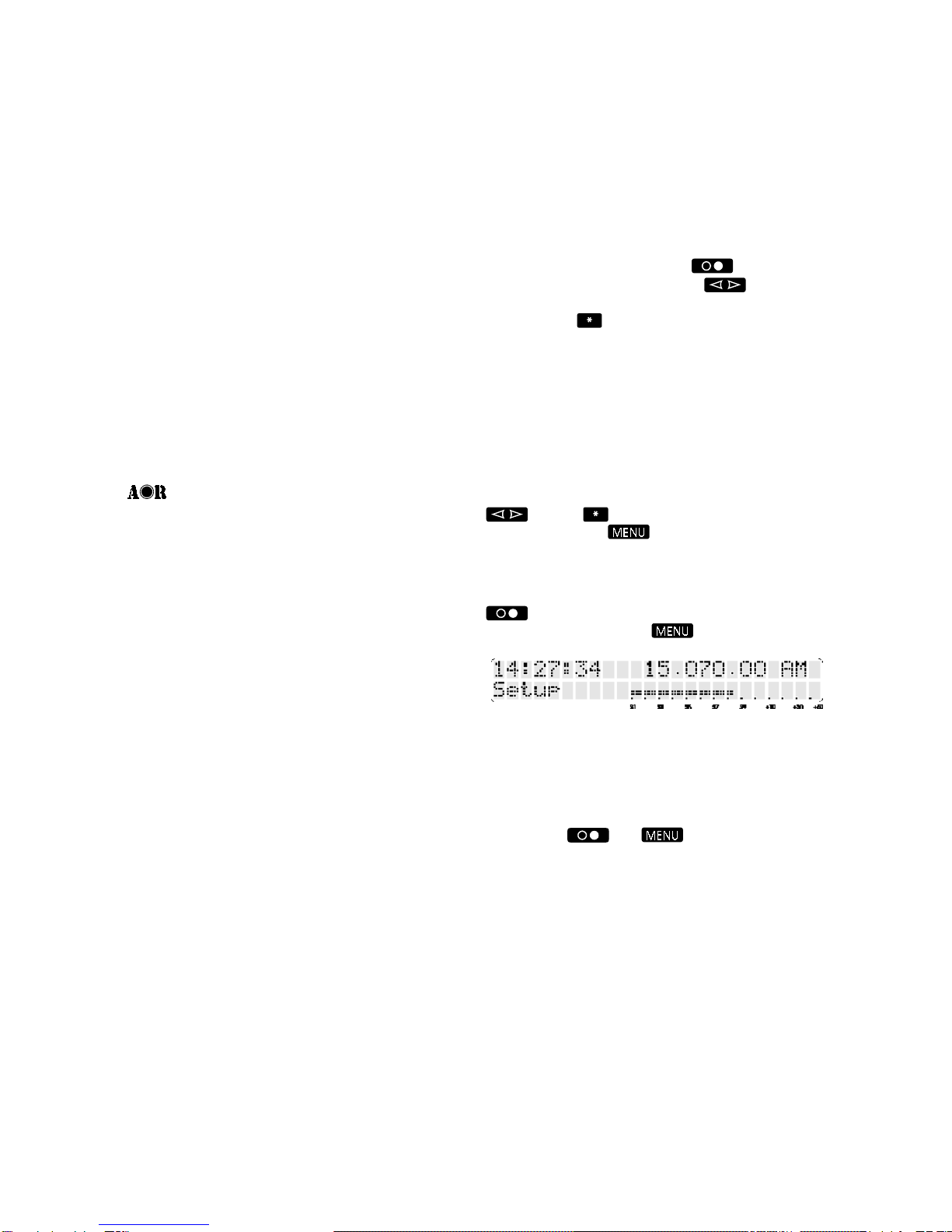
b. The receiver does not have a standard format of
display readout - it can be configured to display time or
pass band shift or filter selection or treble / bass tone
selection or VFO selection or AGC or memory
configuration... whatever YOU choose. The spin-wheel
and the button will retain their last assigned
functions when the button is pressed allowing a
selected function to be changed whilst the S-meter is
displayed.
To return to the SETUP menu and CLOCK display, press
.Todisplay the S-meter and return to the root level
of the menu system, press .
You may tune the receiver, change the volume and
reception mode or select fast tune whilst any menu is
shown on the display because these front panel controls
haveonlyonededicatedfunction.Thesearefixedcontrols,
and are indicated in this manual with white lettering on a
blackbackground,similartotheletteringonthefrontpanel.
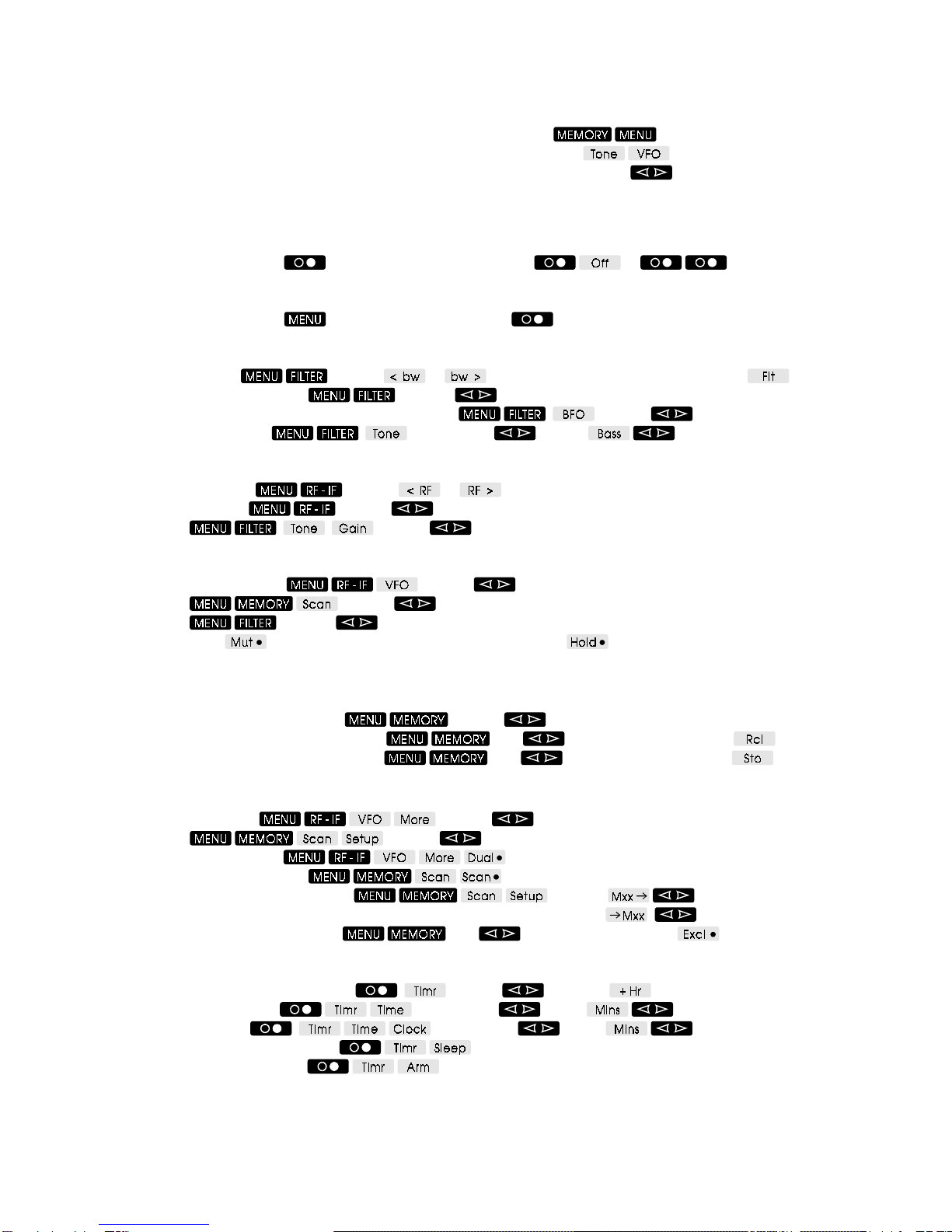
Similarly the and buttons always have a
defined function. The other receiver controls, arranged
beneath the display, are referred to as SOFT-KEYS,
because their function varies according to the context of
theselected menus.Inthese cases thecontroldescription
isdisplayed on the receiver’sLCD andinthismanual with
black lettering on a grey background. When no menu is
displayedon the LCD - when the S-meter is shown -then
the underlying buttons select the menu indicated on the
panel:- MEMORY, RF / IF or FILTER.
c. Each mode can have, and will retain, a different filter
bandwidth(chosenfromthoseavailable),passbandshift
(PBS) setting, BFO setting and AGC speed. When
adjusting any of these settings the values are changed
onlyfor thecurrentmode selected. Squelchvaluefor NFM
modeis heldseparatelyfrom the valueforall othermodes.

AR7030 OPERATING MANUAL PAGE 3
d. It is possible to save and load up to three of your
favourite receiver set-ups, one for casual listening, one
forseriousDXing,onefordatacommunicationorwhatever
you choose. Each mode can have your own choice of
filter bandwidth, pass band offset, BFO setting and AGC
speed, along with global settings of the tone controls,
auto / manual synchronous AM, auto / manual RF
attenuatorand line output levels. All these settingscanbe
held in one of the SETUP MEMORIES, A, B or C. Using
thesetupscan avoidhavingtorecallmanydifferentmenus,
and provides a useful short cut to changing listening
modes.
The setup memories are accessed through the SETUP
menu by turning the spin-wheel until the required
memory (A, B or C) is selected along with the required
function:- to setup the receiver with the settings
held in the memory or to transfer the receiver’s
settingsinto the memory. Press the button to actually
load or save the setup.
e. The AR7030 has two VFOs, A and B - (Active and
Background). Each VFO holds settings of volume, tone,
receivefrequency,reception mode, filter bandwidth, PBS,
BFO, RF attenuator, IF gain, AGC speed, squelch, scan
delay time and scan mode. The contents of the VFOs
canbe exchangedusingthe button, only theactive
VFO can be tuned.
Note: The background VFO data will be lost when power
to the receiver is switched off.
f. The 100 frequency memories store receiver
frequency, reception mode, filter bandwidth, PBS offset
and squelch level. BFO frequency is stored instead of
squelchlevelfor in CW and DATA modes. Once recalled,
(into the active VFO) it is possible to tune away from the
memory data or change mode at will - for this reason
there is little point in storing the same frequency with
different modes in different memories, even when DXing
a broadcast where AM, USB, LSB or Snc modes might
be needed.
Memory contents are not modified by changing any
receiver settings - they will only alter if the button
is pressed. Any previous contents are then overwritten.
g. The receiver’s display is split into several different
areas. The current FREQUENCY and MODE are always
visible, but other information varies depending upon the
operating condition and the menus selected. This
illustration may be useful for reference.
1Auxiliaryinformation(volume,squelchetc)
/ keypad entry
2Receivefrequency
3Reception mode
4Attenuator (A) or preamplifier (P) indicator
5Signal strength meter (S-meter)
6Squelch open / close indicator
7Fasttuningindicator
8Dial lock indicator
9Spin-wheel function
10 button function
11, 12, 13 Menubuttonfunctions

PAGE 4 AR7030 OPERATING MANUAL
2-3 Quick reference guide
Key
Buttons shown white on black are labelled on the front panel, for example
Buttons shown black on grey are soft-keys labelled on the display, for example
The spin-wheel is labelled on the display and shown with up/down arrows, for example Gain
Soft keys shown with a bullet after the legend operate as toggles (on / off). The bullet shows the current state -
solid for on and hollow for off.
Power
To turn the receiver on, press To turn the receiver off, press or
Display
To display the S-meter, press To display the clock press
Filters
To change filter, press and use or Alternatively, cycle through filters with
To shift the filter passband, press and use PBS
To adjust audio frequency in CW and DATA modes, press and use BFO
To adjust audio tone, press and then use Treb or Bass as required
RF and IF Gain
To adjust RF gain, press and use or for adjustment in 10dB steps
To adjust IF gain, press and use Gain (for RF and IF controls together)
OR press and use Gain (for IF gain with filter bandwidth)
Squelch
To adjust squelch level, press and use Sql (for squelch with dual VFO)
OR press and use Sql (for squelch with memory scan)
OR press and use Sql (in NFM mode for general listening)
With squelch active will mute the receiver’s audio with no signal, and will stop scanning if a
signalispresent
Memories
To select and preview a memory, press and use Mxx
To recall from a memory (into the VFO), press , use Mxx to preview then press
To store into a memory (from the VFO), press , use Mxx to preview then press
Scanning
To set scan speed, press and use Dly (for dual VFO scanning)
OR press and use Dly (for memory scanning)
To scan the two VFOs, press
To scan memory channels, press
To set memory block for scanning, press then use From
or To
To exclude memories from scan, press , use Mxx to select then press
Clock and Timer
To set timer run time or sleep time, press and use Mins and
To set timer start time, press and then use Hrs or Mins as required
To set clock time, press and then use Hrs or Mins as required
To start sleep mode countdown, press
To arm timer for switch-on, press

AR7030 OPERATING MANUAL PAGE 5
2-4 Menu structure

PAGE 6 AR7030 OPERATING MANUAL
2-5 Infrared remote controller - quick reference
Key
Number key 0 through to 9
Backspace key (deletes last numeric keypress)
Clear key (deletes whole numeric entry)
All keys labelled +or -will auto-repeat if held pressed.
Tuning
To enter a frequency directly, press
OR press
Frequencies can have any number of digits, with or without a decimal point, up to a maximum of 9 characters.
Resolution of entries can be to 1Hz, with the receiver rounding to the nearest tuning step.
Frequencies of 50kHz or less are taken as tuning step size, not as receiver frequency.
To tune the receiver in steps, press or (step size set as described above).
To switch between active and background VFOs, press (VFO-A is copied to VFO-B if B is not already set).
Volume
To change the volume setting, press or
Mode
Mode key selects CW mode or NFM mode if CW is already selected.
Mode key selects LSB mode or USB mode if LSB is already selected.
Mode key selects AM mode or Sync mode if AM is already selected.
Filters
To change the selected filter, press then or
To move the filter passband, press then or To clear PBS offset, press
To alter the audio tone, press or then or
Memories
To select and preview a memory, press (one or two digits may be entered).
To preview the currently selected memory, press
To select next or previous memories, press or after or have been pressed.
To select and recall a memory (into the VFO), press (one or two digits may be entered).
To recall the currently selected memory (into the VFO), press
To recall the next (and subsequent) memories (into the VFO), press . . . . etc.
To select a memory and store (from the VFO), press (one or two digits may be entered).
To store into the currently selected memory (from the VFO), press

AR7030 OPERATING MANUAL PAGE 7
3 Major Features
The new AR7030 is the result of a combined project
betweenAORandinternationallyacclaimedUKdesigner
JohnThorpe.The AR7030 represents the very latest and
bestever “JT” design concentrating on exceptional strong
signal handling with enhanced microprocessor features
and facilities. It is manufactured by AOR
MANUFACTURING LTD based in Derbyshire, UK.
¬Excellent strong signal handling
InEurope, especially at night, strong signal handling is of
primeconcern andthis is wherethe AR7030standsahead
ofthe field -offeringan IP3 greater than+30dBm(typically
+35dBm, reduced by about 10dB with the preamp
switched on) and dynamic range greater than 100dB in
AM mode with a 5.5 kHz filter and greater than 105dB in
SSBmode with a2.2kHz filter. Thisfantasticstrong signal
handlingis made possible by the innovative configuration
of a lateral DMOS FET QUAD first mixer running at 15V,
relayswitchingin the front end (instead of the more usual
diodes) and the use of shielded inductors throughout the
signalpath.
¬High sensitivity and selectivity
All this and great sensitivity - better than 0.5uV for 10dB
S/N in AM mode and better than 0.3uV for 10dB S/N in
SSB(with thepreampswitched on).Selectivitytoo israzor
sharp offering greater than 95dB @ 10kHz SSB and
almost110dB @ 20kHz.No other receiver in itsclass,nor
indeedat a considerably higherpricecan match the sheer
performance excellence of the AR7030.
¬High Tech
The receiver is built around a TCXO frequency standard
which provides the reference for all its circuitry, ensuring
the ultimate in stability and optimum alignment. A single
loop DDS system provides the clean local oscillator
essential for low reciprocal mixing levels and seamless
tuning in approximately 2.7Hz steps (no tuning “plops” at
regular intervals). The receiver is a double conversion
superheterodyne withintermediatefrequencies of 45MHz
and 455kHz.
The IF filters are self-aligned by the receiver using
advanced microprocessor control, ensuring “spot on”
alignment and symmetry of passband characteristics
essential for serious ECSS listening. The main PCB will
acceptanumber ofdifferentfiltersincludingvariousMurata
typesand Collins mechanical units,allwill be self-aligned!
The displayed filter bandwidths are not fixed but actually
measuredby thereceiverpermitting variousdisplayssuch
as 2.2kHz, 2.3kHz, 2.4kHz, 2.5kHz etc depending upon
the particular filter fitted.
¬Computer control port
Virtually every aspect of the AR7030 is controllable via
the REMOTE port. The AR7030 may be connected
directly to a host computer such as a PC (via RS232 link)
with which, for example, frequency memories may be
loaded, frequency and mode changed and signal activity
logged - expanding the listening station even further.
¬All mode receive over a wide
frequency range
Allreception modes are availableasstandard: USB, LSB,
CW, AM, Synchronous AM, NFM, DATA. The receive
coverageis0- 32MHz, theAR7030hasnotbeen disabled
below 150 or 30 kHz, or made insensitive in the medium-
wave band. The standard fitted IF filters include: 2.2kHz,
5.5kHz, 7.0kHz and 10kHz with two additional positions
available for CW or other filter options.
¬Auto synchronous tuning
The receiver is capable of tuning itself automatically in
synchronous AM mode using a new variable bandwidth
synchronousdetector. Simply select synchronous mode,
tune the receiver to approximately the correct frequency
so that intelligible audio can be heard and wait... within a
few seconds the AR7030 will sample the frequency, tune
to the carrier (its great watching it tune itself!) and lock
solidlyonto the station. Should you prefer,youmayselect
fully manual operation of the synchronous detector.
¬Pass band tuning
(even on synchronous AM)
Enhanced features include pass band tuning of approx
±4.2kHz, variable audio pitch on CW and DATA modes
andanadvanced, self tracking, synchronous detector for
AM listening to eliminate the effects of transmitter or
receiver drift as well as reducing distortion from selective
fading.The passband tuning maybe usedinsynchronous
AM mode to select synchronous USB, LSB, DSB or
anythinginbetween.
¬Full AGC control plus IF gain
A specially developed AGC release characteristic
producesoutstandingSSB qualitywith quickrecovery from
strongsignalsandnoisespikes.Gentlesignalcompression
has also been included to reduce the audible effects of
noise pulses. An IF gain control is available along with
three AGC speeds and AGC defeat.
A built-in six level attenuator provides many levels of
sensitivity:-+10dB, 0dB, -10dB, -20dB, -30dB and -40dB,
howevergiven the excellent strong signal handling of the
AR7030 this is going to be a control rarely required! The
receivercan automatically switchinthe attenuator to keep
incomingsignals within itsAGCrange. Of course youmay
manuallyselect attenuation should you prefer.
¬Aerial input including whip amplifier
The rear panel of the AR7030 has inputs for a wire aerial
withgroundconnection,50OHMSO239 connection plus
selectionof ahighimpedance whipamplifierwhich isfitted
asstandard.
¬Audio output
Audio output is of high quality and clear tone when using
the built-in top mounted speaker. A 3.5mm external
speaker jack is provided on the rear panel which mutes

PAGE 8 AR7030 OPERATING MANUAL
the internal speaker, the amplifier provides more than 2
WATTS of audio-there are even treble andbasscontrols.
A stereo 3.5mm front panel socket provides headphone
output from a separate internal stereo amplifier and may
drive mono or stereo ‘phones. The auxiliary outputs (left
and right) have separately adjustable levels and may be
used to drive an external recorder or data decoders.
¬Dot matrix LCD
A 48 character, rear illuminated dot matrix LCD with rear
panel adjustable contrast provides a huge amount of
information, a wide range accurate signal meter and text
basedmenus.
¬Assignable controls
Assignablecontrolsenableyoutoplace thefunctions YOU
wantat your fingertips -theyretain the last used operation
whenthe menus are removed, and include apressbutton
and a spin-wheel .
¬Infrared remote controller
Afull featured32 buttoninfraredremote controlis provided
as standard and provides access to all commonly used
facilities, including: tuning, volume, tone, memory
functions, pass band shift and filter selection, as well as
providing a numeric keypad for direct frequency entry.
TWO infrared sensors are employed, one on the front
panel and one on the rear, so that the controller may be
used from almost any position around the receiver.
¬Stylish strong cabinet
The AR7030 features a custom CNC machined solid
aluminium front panel with extruded aluminium shaped
sides, metal top, bottom and rear panels. The front panel
finish is brushed and anodised with the sides and other
surfaces toned in a matching textured paint. Smooth
curved lines, detailed panel breaks, top mounted domed
speakergrille and ergonomically placed controls spell out
the attention to detail of this robust, solid cabinet.
4 Precautions
4-1 Location
Do not use or leave the receiver in direct sunlight
(especially the LCD). It is best to avoid locations where
excessiveheat, humidity, dustandvibration are expected.
Always treat the receiver with care.
Take care to avoid spillage or leakage of liquids into the
receiver and a.c. power supply. Special care should be
takento avoid liquid entering aroundthecontrols,through
the speaker grille or via the connection jacks.
Avoidstaticdischarge fromaerial systemsespecially when
usinglongwires - earth them to a central heating radiator
or similar earthing point in order to discharge the wire
beforeconnectiontothereceiver. Always disconnect and
earth any external aerial system if an electrical storm is
expected.
Avoidarapiddisconnectionthenreconnectionof thepower
supply.Ifdisconnected, leave at least two secondsbefore
reconnectingagain. Ensurethatall powerconnectionsare
secure.
AvoidstrongRFfields fromnearbytransmitters. Ifin doubt,
disconnecttheAR7030fromtheaerial and switch the set
off.
4-2 Looking after your receiver
Alwayskeep the receiver free from dust and water.Use a
soft, dry cloth to gently wipe the set clean. Never use
abrasivecleaners or organic solvents which may damage
certainparts.
4-3 Power requirements
The AR7030 is designed for operation from its supplied
mains adapter. Operation is possible from a d.c. supply
of12 to 15V,which should be able to supply up to 800mA,
but for full performance always power the receiver from
15V d.c rather than from 12V. (The receiver’s frequency
coverageisnotguaranteed above30 MHzwhenoperating
from a 12V supply).
EMC NOTICE - This receiver may not fully comply
with the E.C. EMC directive if operated from an
external power source other than the supplied AC
adapter.
The d.c. input socket uses a 2.1mm coaxial power
connector, and a 14mm long plug is recommended. This
connectorisconfiguredCENTREPOSITIVE,thechassis
ofthe receiver is at negative ground. The low noise power
supplyprovided ispre-wiredand provides aregulated15V
d.c.outputwith suitableconnectorsbeingfittedasstandard
for the a.c. mains input and connection to the AR7030.
TheAR7030has a rear panel socket for connection of an
RFearth,allowingaseparateearth to be taken to a water
pipe,central heating system radiatororexternal earth rod.
If fitting a separate external earth rod, consider the
implicationscarefullyif yourmainssupplyusesaProtective
MultipleEarth (PME) system. If in doubt consultanexpert
electrician. Never earth to a gas pipe!
SAFETY NOTICE - Always disconnect the power
supply from the a.c mains when not in use.
4-4 Aerial (antenna) connection
TheAR7030hastwoaerialinputs,selectedbyarearpanel
switch,allowing threebasic typesofconnection (theactual
choice of suitable aerial is almost limitless).
1. 50 OHM (unbalanced) SO239 socket for connection
ofdipoles,longwireswithmatching devices,active aerials,
verticals,yagis etc.
2. WHIP may be selected to activate an impedance
matching amplifier when a telescopic aerial or very short
wire is fitted to the 50 OHM SO239 socket.
3. WIRE aerial input is used for connection of long wire
or similar relatively high impedance aerial systems.

AR7030 OPERATING MANUAL PAGE 9
5 Controls and functions
Front panel
name for a tuning mechanism, in this operating manual it
is referred to as the MAIN DIAL.
The receiver tunes in a very smooth manner with
increments as small as 2.655 Hz. Excellent tuning
dynamicsincrease the rateoftuning depending upon how
fastthetuningcontrol isrotated andthemodeofreception.
Itispossibletoelectronicallylock the main dial to prevent
accidental tuning. A lock indication (reversed L) is
displayed on the LCD in this case.
5-4 Fast tuning button
FAST tuning increases the speed of tuning when using
themaindial.TheletterFisdisplayedafterthekHzofthe
frequencydisplay whenfast tuning isselected -the
buttonswitches thismode on andoff.If tuningin automatic
synchronous AM, the fast tuning mode is cancelled
automatically when the receiver samples frequency and
locksontothe transmission.
5-5 Mode selection buttons
The mode selection buttons are located in the top right
corner of the front panel. They select all of the available
modesin sequence: Dat (datareception),CW,LSB,USB,
AM,Snc(synchronousAM)andNFM,thesequencethen
repeating. The current mode is displayed to the right of
the frequency readout on the LCD.
5-1 On/Off power switch
This button, located in the upper left corner of the front
panel,switchesthesetonandoffand selects the SETUP
menuforgeneralconfigurationofthereceiverandsetting
of the clock and timer facilities.
Toswitch thereceiveron, connectasuitable powersource
andpressthepowerswitch forabout one second.
To switch the receiver off, press the power switch
TWICE,or usethe soft-keyfromtheSETUP menu.
Whenswitched off, whilst the receiver is still connected to
its adapter, the clock time display will continue with a dim
backlight.
5-2 Liquid Crystal Display (LCD)
Display of operating condition is provided by a high
contrast, green backlit, dot matrix LCD. Information
includes frequency, mode, bandwidth etc. Menu legends
forthecontrolsbeneaththedisplayarealsoprovidedalong
with an accurate 70 segment signal strength meter
(S-meter).
5-3 Main rotary tuning control
- MAIN DIAL
The large rotary tuning control is prominently located to
the right of the front panel. This control changes the
receivedfrequencyupanddown.Often referred to as the
VFO (Variable Frequency Oscillator), a rather historic

PAGE 10 AR7030 OPERATING MANUAL
5-6 Volume control
The volume is adjusted by the rotary encoder located in
the lower left of the front panel. The volume level is
displayedas a percentageonthe top left oftheLCD whilst
the control is turned. The range is 0% (minimum) to 96%
(maximum).
Note: It is normal for very low level audio to emanate
from the speaker even when the volume is at 0%,
especially in NFM mode.
5-7 Spin-wheel
This encoder is used to make selections from various
menusand to change the values of receiver settings such
aspassbandshift(PBS),IFgain,squelchetc.Thefunction
of the spin-wheel at any instant is displayed above it on
the LCD.
5-8 General button
This button is used to make selections from menus as a
soft-key. The assigned function is displayed above it on
the LCD.
5-9 Memory menu button
Initially used to choose the MEMORY menu for selection
of memory channel, scan parameters and audio mute. It
is also used as a soft-key to make selections from other
menus.
5-10 RF and IF settings button
Initially used to choose the RF gain / attenuator, IF gain
and VFO selection menu. It is also used as a soft-key to
make selections from other menus.
5-11 Filter menu button
Initially used to choose the filter bandwidth display
/ selection menu along with pass band shift (PBS) and
audio tone control. It is also used as a soft-key to make
selections from other menus.
5-12 Headphone socket
This 3.5mm socket will provide output to either stereo or
mono headphones, no switching is required. Connection
to this socket disables the internal speaker and any
speaker connected to the rear EXT LS socket.
Headphones should be of a nominally low impedance
around 8 to 200 OHMS.
5-13 Bail bar
The front of the receiver may be lifted up clear of the
table top to allow easy access to the front panel controls
and clear visibility of the LCD. Pull the bar forward to lift
thefront of the receiver upward, rubber cushions prevent
slipping on a table top.
5-14 Internal speaker
The AR7030 is fitted with a top mounted loudspeaker
which provides excellent audio reproduction under most
conditions.
Rear panel

AR7030 OPERATING MANUAL PAGE 11
5-15 Computer control socket
Thisaccessorysocket isused forconnection toacomputer
via RS232 link.
The socket is a 5-pin / 240° DIN with the following
connections:
Pin 1 External supplyoutputavailable,
nominal 14V @ 100mA MAX
Pin 2 RXD
Pin 3 TXD
Pin 4 No connection
Pin 5 GROUND
Connection to a PC should be as follows:
AR7030 PC 9-D PC 25-D
pin 2 pin 3 pin 2
pin 3 pin 2 pin 3
pin 5 pin 5 pin 7 (GND)
5-16 Auxiliary equipment socket
This accessory socket is used for connection to tape
recorders and data decoders. Two audio outputs are
providedunaffectedby volume and tone settings.Amute
input and a 455 kHz IF output are also present.
The socket is of an 8-pin DIN, circular configuration with
pin 8 being at the centre. The connections are as
follows:
Pin 1 MUTE - ground to mute the receiver
(in conjunction with a transmitter)
Pin 2 GROUND
Pin 3 External supplyoutputavailable,
nominal 14V @ 100mA MAX
Pin 4 Auxiliary audio output (LEFT) 0-800mV
from 1kohm
Pin 5 Auxiliary audio output (RIGHT) 0-800mV
from 1kohm
Pin 6 Aux control relay contact A
(for tape recorder motor control)
Pin 7 Aux control relay contact B
(for tape recorder motor control)
Pin 8 455 kHz IF output -20dBm / 50 ohms
The aux relay can only be used for
low voltage control, NEVER
CONNECT MAINS TO THE AUX
RELAY CONTACTS.
5-17 DC power input
Thisisa 2.1mm coaxial power socket designed to accept
external d.c. input from an ac adapter. See section 4-3
for supply details.
5-18 External speaker output socket
This 3.5mm mono jack socket provides audio output to
drive an external speaker unit. Connection to this socket
automatically disables the internal speaker but not a
headphone if connected to the front panel socket.
An external speaker should have a minimum 8 ohm
impedance and power handling of 2 watts or greater.
5-19 Display contrast adjustment
This rotary control adjusts the LCD display contrast and
viewing angle. Adjust this for optimum display readability
- it may need re-adjusting if the viewing angle is changed
or if there is a significant change in temperature. The
normalcontrol position will often beslightlylessthan fully-
clockwise.
5-20 Ground (chassis) connection
Ground connection for an external RF earth. This often
reducesnoise.
5-21 Wire aerial connection
Connect a long wire aerial to this terminal.
5-22 Antenna selection switch
This slide switch is used to select the aerial connection
and function: 50 OHM, WHIP or WIRE.
5-23 50 OHM aerial socket
50 OHM SO239 socket designed for connection to
unbalanced50OHM aerials with coaxial feeders, or, with
the selection switch in the WHIP position, a telescopic
aerial.

PAGE 12 AR7030 OPERATING MANUAL
Infrared controller
5-24 Filter change key
Oneof a group of six keys contained within an outline, the
key choosesfilterselection forsubsequentchange
withthe and keys. When is pressed
the receiver briefly displays the legend Filter along with
the sequence number (1 to 6) of the current filter (the
standardreceiver displays 1 to 4 because it is fitted with 4
filters). This message is displayed for about 5 seconds
then the display returns to its previous condition.
For example, if the narrowest filter (2.2 kHz as standard)
is currently selected, the display will show Filter 1
The and keys can be used to step through
theavailablefilterswiththedisplayconfirmingtheselection.
and will continue to modify the filter
selection until one of the other change keys
orthe or key is pressed.
5-25 PBS change key
Oneof a group of six keys contained within an outline, the
key selects passband shift forsubsequentchange
withthe and keys. When is pressed
the receiver briefly displays the legend PBS along with
thecurrentshift valueinkHz(-4.2to+4.2with 0.0indicating
no shift). This message is displayed for about 5 seconds
then the display returns to its previous condition.
The and keys can be used to increase or
decrease the passband shift value with the display
following the changes, and will continue to modify PBS
untiloneoftheotherchangekeys
or the or key is pressed.
ThePBS canbe quickly turnedoff(setto zero)bypressing
then .
5-26 Treble change key
Oneof a group of six keys contained within an outline, the
key selects treble audio tone for subsequent
change with the and keys. When
is pressed the receiver briefly displays the legend Treb
along with the current value in dB (-8 to +8 with +0
indicatinga flat response). This message isdisplayed for
about 5 seconds then the display returns to its previous
condition.
The and keys can be used to increase or
decrease the treble tone value with the display following
the changes, and will continue to modify treble tone until
one of the other change keys or
the or key is pressed.
5-27Bass change key
Oneof a group of six keys contained within an outline, the
keyselectsbassaudiotoneforsubsequentchange
withthe and keys. When is pressed
the receiver briefly displays the legend Bass along with
the current value in dB (-9 to +9 with +0 indicating a flat
response).This messageisdisplayed forabout5 seconds
then the display returns to its previous condition.
The and keys can be used to increase or
decrease the bass tone value with the display following
the changes, and will continue to modify bass tone until
one of the other change keys or
the or key is pressed.
5-28 Increase and decrease keys
The and keysarecontainedwithinagroup
of six and are used to change the selected filter or values
of PBS or tone control settings (see above). They can
also be used to step through the frequency memories if
used after either the or keys have been
pressed.These keyswillauto-repeat ifhelddown formore
than half a second.
5-29 Tune-up and Tune-down keys
These two keys allow the receive frequency to be varied
(tuned) upwards or downwards in any selected step size
between 2.7 Hz and 50 kHz. These keys will auto-repeat
if held down for more than half a second.
Thestepsize isset byenteringafrequencyvia thekeypad
of 50 kHz or less. Tuning using the and
keys can be done in addition to using the main dial.

AR7030 OPERATING MANUAL PAGE 13
5-30 Volume increase and decrease keys
These two keys allow the volume of the receiver to be
varied between minimum and maximum. They will auto-
repeat if held down for more than half a second.
5-31 Store into memory key
The key is used to store the current receiver
frequency and mode into the current memory channel.
The legend Stored .. on the receiver’s display confirms
operation,andappears for about 5 seconds in the top left
corner. Keying in a memory number before pressing
will use that memory.
5-32 Memory preview key
The key is used to preview, rather than recall,
thefrequency contained inthecurrently selected memory.
The memory’s stored frequency is displayed in the top
left corner of the LCD for about 5 seconds. If no data is
stored in the memory, the frequency 000.00 is displayed.
A particular memory may be examined by keying in its
number then pressing . Subsequently pressing
or will step through memory channels.
5-33 Change VFO key
The keyswaps between activeandbackground
VFOs (A and B). If no data has been previously stored in
the background VFO, the current contents of the active
VFO are copied to the background VFO which is then
recalled... nothing appears to happen on the LCD in this
situation as the contents of the two VFOs are identical.
Each VFO contains nearly all of the current operating
conditionsof thereceiver,includingfrequency,mode, filter,
PBS, volume, treble, bass, squelch, IF gain, AGC speed
and tuning step size for and .
Note: The Background VFO information is lost when
power to the receiver is switched off.
5-34 Mode select keys
These keys, contained in a group of three, are used to
directly select the reception mode as an alternative to
stepping through a list of modes with the front panel
buttons. When any of these keys is pressed the mode
specified first is selected unless that mode is already in
use, in which case the second mode is chosen.
Foe example, to change from AM mode to USB mode,
the key would be pressed twice. Subsequent
presseswould thentogglebetween LSB andUSBmodes.
5-35 Number keys . . . and
The numeric keypad is used to enter frequencies, step
sizes and memory numbers. The receiver will display
keystrokes in the top left corner of its display as they are
entered until input is completed or a long time elapses
(about 20 seconds after the last keystroke).
The key is used when keying frequencies to enter
fractionsof kHz or MHz as desired. It is not neededwhen
enteringwhole numbers.
5-36 Backspace key
Pressing will delete the last keypress from your
entry. This only works with the number keys while the
current keyed input is displayed on the LCD - it will not
undo an operation once it is completed.
5-37 Clear key
The keywill delete a whole line of entered digits to
allow a fresh start.
5-38 Memory recall key
The key is used to directly recall memory
frequencies into the VFO. Each time the key is pressed,
the receiver advances to the next memory channel and
receives what ever frequency is stored. The and
keys may also be used in conjunction with
to select the starting position for memory recall. When
the desired memory channel is displayed in the top left
corner of the LCD, the key then recalls the data
and tunes the receiver.
Additionally the key can be used in conjunction
with the numeric keypad to directly recall a memory. For
example to recall and listen to the frequency stored in
memory 25, press . The legend Mem 25
is briefly displayed in the top left corner of the LCD to
confirmselectionandthereceiveristunedtothememory
frequency.
5-39 Frequency entry keys
These keys complete a key entry and tune the receiver.
Frequenciescan beentered inMHzor kHzand terminated
with the appropriate key. Frequency accuracy can be to
1Hz,with the receivertuningto its nearest step(maximum
error is 1.4Hz).
Forexample, to tuneto15.070 MHz (which is15070kHz),
press
(to enter frequency in MHz)
or press
(to enter frequency in kHz)

PAGE 14 AR7030 OPERATING MANUAL
6 Receiver operation - Main functions
It may be useful to refer to the overview and quick
referenceguides in section2of this manualwhilstworking
throughthissection.
6-1 First switch-on
Connect an appropriate aerial to the input on the rear of
the receiver and make sure that the ANTENNA SELECT
switch is correctly set. The selection of aerial depends
upon your location and specific requirements but may
include a dipole or long wire.
Plug the d.c. cable of the supplied mains adapter into the
power socket on the rear of the AR7030 and then plug
the adapter into the mains supply. Never connect the
receiver directly to the a.c. mains.
Press and release the power button , the receiver
will turn on and the LCD back light will illuminate.
Firstly,checkthe clock time - it should be displayed at the
topleft corner of the display. If it has startedfrom00:00:00
instead of reading a sensible time then it is likely that the
small rechargeable battery in the receiver has run down.
This battery operates the clock and retains some
calibration data in memory, so you should work through
sections 6-2 and 6-3 to restore this data before using the
receiver. To re-charge the battery leave the receiver
connected to its mains adapter for about 48 hours (it
doesn’tmatterwhetherthereceiverisswitchedonoroff).
The charge should last for many months.
If the clock looks OK then you can skip sections 6-2 and
6-3 for the time being, but have a look at them later.
6-2 Filter calibration
If the data retention battery is discharged, or you have
addedextra filters,or you havejust gotboredwith listening
toyour radio then you can run throughthefiltercalibration
procedure.This is an automatic process once startedand
takes about half a minute. Choose the SETUP menu by
pressingthe button andthen chooseCONFIGURE
by pressing (the soft-key function shown on the
display above the button). Rotate the spin-wheel
one click anti-clockwise to display Filter calibrate: and
press .
The receiver will display the filter number currently being
calibrated,signal level, -20dB and -6dB frequency offsets
for high-side and low-side calibration. The AR7030
generates and injects a variable frequency signal from
the DDS and uses the AGC system to measure the filter
passband characteristics. In the process, the -6dB
bandwidth, centre frequency and USB and LSB carrier
insertionfrequencies aredetermined.A listoffilters isthen
generated in ascending bandwidth order, regardless of
the physical position in which any filter has been fitted.
Ideally the calibration should be made when the set is at
its normal operating temperature (i.e. after about 30
minutesof use). You may carry out thecalibrationas often
as you like... it will not affect the performance of the
receiverif run morethanonce but it isinterestingto watch!
Thedisplayed bandwidthisrounded tothenearest 0.1kHz
so there may be slight variations in the results between
different calibration runs. Some filters are quite sensitive
to temperature changes.
Note:Most filter manufacturers usually quote a
minimum
pass-band bandwidth (and a maximum stop-band
bandwidth)soinpracticefiltersoftenmeasurewiderthan
their specification. The receiver, of course, doesn’t know
the spec - it can only measure what’s fitted. In fact the
standard5.5kHz filter fitted to the AR7030 has a specified
bandwidth of 4kHz, so be careful when comparing the
filtercalibrateresultswith bandwidthsspecified foroptional
filters or other receivers.
Ceramic filters, such as the Murata ones fitted to the
AR7030, have very rounded filter characteristics. Many
people like the AM audio sound produced by this type of
filter, however such a filter is very difficult to accurately
measure. Collins mechanical filters can be fitted to the
AR7030 and have much sharper shoulders making them
easier to measure. Collins produces a 4.0 kHz AM
mechanical filter which will provide excellent results, the
optional 500 Hz CW mechanical filter and 2.5 kHz
mechanical filter are also very good. The displayed
bandwidthisnotimportantforthereceiver’sperformance
- it is only used by the receiver to build its filter table in
ascending order and as identification of which filter is
selected at any time.
Typical displayed bandwidths for the standard filters are:-
Filter 1 Displays as 1.8 to 2.3 kHz
(Spec. nominal 2.2 kHz)
Filter 2 Displays as 5.4 to 5.9 kHz
(Spec. minimum 4kHz)
Filter 3 Displays as 6.3 to 7.0 kHz
(Spec. minimum 6kHz)
Filter 4 Displays as 9.5 kHz
(Spec. minimum 9kHz)

AR7030 OPERATING MANUAL PAGE 15
Typical displayed bandwidths for the optional Collins
filters are:-
Collins 500 Hz Displays as 0.7 or 0.8kHz
Collins 2.5 kHz Typically displays as 2.3 kHz
Collins 4.0 kHz Typically displays as 3.5 kHz
When the filter setup is complete, the receiver’s display
returns to frequency readout.
6-3 Memory restoration
Ifthedataretentionbatteryisdischarged(refersection6-
1)then some of the setup memories may contain rubbish
whichwillcauseunusualoperationofthereceiver.Toavoid
this problem the following procedure should be followed
after the filter calibrate operation. It is only necessary to
do this if the clock time has been lost.
FromtheSETUP menu (press the button if Setup
is not displayed above the spin-wheel), Rotate the spin-
wheel one click anti-clockwise so that the legend Deflt
Set is displayed then press the button. The legend
Loaded.. confirms that default settings are in operation.
Rotate the spin-wheel again one click anti-clockwise and
press (thesoft-key legend above the button),
then repeat twice more. This will save default settings in
all three setup memories - the display should show
SetC:Save then SetB:Save then SetA:Save.
Now enjoy !
6-4 Changing receive frequency
There are THREE main ways in which receive frequency
maybe selected and tuned,thechoice is dependant upon
the type of operation (transportable / desktop) and
personalpreference.
a. Main rotary tuning dial
Themostobviousmethodfortuningthereceiverisbythe
rotary tuning control (main dial). This is the traditional
approach and provides the best human interface to the
receiver.
To increase displayed frequency rotate the main dial
clockwise.In SSBmodesthe tuningspeedis around1kHz
per revolution for silky-smooth tuning. As the main dial is
rotatedmore quickly, the receiver steps upthetuning rate,
ifthemaindialcontinuestoberotatedquickly,sothetuning
speedis increased again and again. Careful attentionhas
been paid to the tuning dynamics so that the operator is
largely unaware that anything happens and the tuning
speedremainsintuitive.
Todecrease the displayed frequency, rotate the maindial
anti-clockwise,auto increase in tuning speed operates in
bothdirections.
Note:The maindialuses a mechanicalencoder, and from
time to time, as with all such devices, contact noise may
causethe display tocreepup or downveryslightly. Should
this happen a tiny movement of the tuning knob will be
enoughto clearthe problem. Thecontrol likestobe used...
give it a few turns once in a while.
FAST TUNING: Should you wish to tune VERY quickly,
such as when changing bands, it is possible to manually
increase the tuning rate of the receiver.
Above-leftof the main dial at about the 10 o’clock position
isthe button.Pressingthis changes the frequency
display by putting an F(for fast) where the fractions of
kHzdigits are normallyshown.The tuning rate ofthemain
dial will be very fast while the Fis displayed.
Tocancelfasttuning,simplypressthe buttonagain,
it acts as a toggle.
Note: When tuning in AUTO SYNCHRONOUS AM, the
FAST tuning is automatically cancelled whentheself tune
processstarts.
b. Numeric keypad
For rapid change to a known frequency, the infrared
controllerkeypadprovidesthe simplest,quickest andmost
accurate route. Frequencies may be entered as MHz or
kHz, there is backspace correction and cancel entry to
further add to convenience.
The numeric keys to are used in conjunction
with , , , and .Asummary
of key operation is as follows:-
to Used to enter the digits of desired
frequencies.
Used as a decimal separator when
entering frequencies as MHz or kHz.
Used to complete frequency entry as kHz.
Used to complete frequency entry
as MHz.
Used to cancel frequency entry and abort
theprocess

PAGE 16 AR7030 OPERATING MANUAL
Used to backspace frequency entry from
the right hand side, each additional press
of this key deletes one further figure. This
is useful for correcting a mistake without
the need to re-enter the whole frequency.
Frequency entry using the infrared controller is accepted
in the range 0.051 MHz (actually 50.977 kHz) to 32 MHz
(actually32.01672 MHz).Frequencies abovethespecified
top limit up to about 44 MHz will result in the receiver
tuning to the top frequency limit just above 32 MHz.
Incorrect frequency entry usually results in an error
messageKeypad ?? beingdisplayedin the topleftcorner
of the LCD.
You cannot key in a frequency of 50 kHz or less to tune
thereceiver.Insteadthisishowthetuning keys’ step size
is set.
Examples: Anexample frequency entry using the
key of 693 kHz (0.693 MHz), as follows:-
Asthe frequency is entered through the keypad,thedigits
are displayed in the top left hand corner of the LCD, to
the right of a >symbol.
When the entry is completed using the key, the
frequency transfers to the main VFO frequency readout
of the LCD and the top left display returns to its previous
state.
Another example of frequency entry for the international
search and rescue frequency 5680 kHz (5.680 MHz)
would be as follows:-
When the key is used, the AR7030 automatically
calculates where the decimal MHz separator should be
inserted.
It is possible to enter frequencies using and a
decimal point for hundreds and tens of Hz. This may be
usefulforcertain data communications applications such
as FAX. For example, to tune to 132.5 kHz type:-
Asfrequency increases past a few MHz, itbecomesmore
natural and easier to enter frequencies directly in MHz.
An example frequency entry of 14.250 MHz (14250 kHz)
would be as follows:-
Asthefrequencyisenteredthroughthekeypad,theinput
is displayed in the top left hand corner of the LCD, to the
right of a >symbol. When the entry is completed using
the key, the frequency transfers to the main VFO
frequency readout of the LCD and the top left display
returns to its previous state.
It is not necessary to add leading or trailing zeros to any
frequency. Entry of 14.250 MHz may alternatively be:-
Thethree trailing zeros will be added automatically to the
display by the AR7030.
Similarly, when frequencies below 1 MHz are entered, it
is not necessary to precede with zeros. To enter a
frequencyof 0.198 MHz (198 kHz) using the key:-
The preceding zeros are assumed by the AR7030 and
trailing zeros added automatically.
Cancellingfrequency input: Atanytimeduringfrequency
entry via the keypad, the process may be aborted by
pressing the key. Any input displayed in the top
left corner of the LCD is cancelled and the displayed
reverts to its previous state.
Correcting frequency entry during input: Should a
mistakebe madewhileentering frequency viathekeypad,
it may be corrected using the back-space key .
However, the entry cannot be corrected once the
or keys have been pressed.
Each time the key is pressed, the frequency entry
(progress is displayed in the top left of the LCD following
a >symbol) is deleted from the right-most digit (the last
one entered). Each additional press of this key deletes
one further digit. This is useful for correcting a mistake
without the need to retype the whole frequency.
For example, if the entry has been mis-typed as
and the mistake realised before the key is
pressed,press to delete the figure 4. Enter to
replaceit,thencompletetheprocess by pressing .
c. Tuning step keys
Occasionally it is convenient to tune up and down the
frequency spectrum in specific step sizes such as 5 kHz
forshort wave,9 kHz forEuropean mediumandlong wave
or 10 kHz for US medium wave. The step tuning facility
alsomakes fine tuning sprawling amateur band netseasy
when the receiver is just out of reach.
First the tuning step size needs to be defined and this is
achievedusingthenumerickeypad.Forexample,toselect
atuning step of 5 kHz from the from the infrared controller
type:-

AR7030 OPERATING MANUAL PAGE 17
Other permutations are also accepted:-
or
or
The LCD briefly confirms entry as Step 05.00 in the top
left of the LCD to show that the entry is accepted as a
step size and not a frequency to tune to.
Each time the keys or are pressed, the
receiver will step up or down by 5kHz (as this is the step
size currently selected). The LCD frequency readout
changes as the receiver tunes to new frequencies. You
may hold down the or keys for
continuoustuning in the selected step size.
To select a tuning step of 10 Hz, type
To select the smallest possible tuning step, type
VFO-A and VFO-B can store different step sizes.
Note: The receiver stores all of its frequencies in binary
steps (the AR7030 doesn’t think in decimal!) and as a
resultthe last digit of the displayed frequency may gain or
loose 10 Hz especially if the TUNE keys are used
repeatedly. This is simply because the step size cannot
be stored as an exact number of kHz.
d. Other methods of frequency selection
It is also possible to recall memories into the active VFO
asameansof changingfrequency. Forinstance,a number
of memory channels could be set up with the centre or
most popular section of your favourite amateur bands or
broadcast bands then recalled as the starting point for
manualtuning.
Frequencyselection may also be accomplished using an
external computer connected to the remote port.
6-5 Changing reception mode
The AR7030 is equipped with seven reception modes as
standard, these being:- DATA, CW, USB, LSB, AM,
Synchronous AM and NFM.
Mode selection buttons are ergonomically placed above
the main dial, located toward the top right corner of the
front panel. These mode buttons have only one function
and are not used for anything else, this makes them
available at all times - reception mode may be changed
regardlessof what menuisdisplayed on the AR7030LCD
(except when it’s switched off!).
The mode buttons select from a rolling list:-
Dat (data reception)
CW
LSB
USB
AM
Snc (synchronousAM)
NFM
The reception mode is displayed to the right of the
frequency readout on the LCD. Any reception mode may
be selected on any frequency within the receiver’s short
wave coverage.
Modemayalsobechangedusing the keys of the infrared
controller , and . Data
reception mode cannot be selected from the infrared
controller.
The keys select the mode listed first (to the left) i.e. CW,
LSB and AM unless that mode is already in operation,
when they will select the mode listed second i.e. NFM,
USB and SYNC.
AM Amplitude Modulation - Used by broadcast services
throughout the world on long wave, medium wave and
short wave.
Forbest results use either the 5.5 kHz IF filter (fornormal
operation) or the 7.0 kHz IF filter for higher fidelity when
signalsare strongand freefrominterference. You willhave
to experiment with the setting of the AGC so medium
speed (Med) may be a good starting point.
Snc Synchronous AM - the AR7030 uses a new
automatic variable bandwidth synchronous AM circuit
which is capable of automatically tuning the receiver and
locking on to fading transmissions. It is also possible to
select manual synchronous AM although the default is
automatic.
SynchronousAMisaspecialformofAMdetectioncapable
of reducing the effects of fading on long wave, medium
wave and short wave signals.
LSB Lower Side Band - is a form of Single Side Band
(SSB). LSB tends not to be used commercially but is
extensivelyused by radio amateurs on frequencies below
10 MHz. This assists the separation of commercial and
amateurusers on traditionally sharedbandsand prevents
them from unintentionally speaking with each other.
SSB is a very efficient method of transmission as the
unwanted second sideband and carrier have been
removed. This allows the full transmitter power to be
employedin carrying useful information within the wanted
sideband. As a result greater distances are possible on
SSB and a smaller frequency bandwidth is required than
most other modes.
The AR7030 uses true carrier re-insertion so that voice
becomes intelligible - with ease. However due to the
complexitiesof SSB, audio may never sound quite100%
naturalandoften listeners comment on it sounding a little
like Donald Duck. This is normal, and with practice you
soon become used to tuning and listening to SSB... it is
not a problem specific to the AR7030.

PAGE 18 AR7030 OPERATING MANUAL
ThesettingofAGCspeedis important for SSB reception.
Usually a SLOW setting provides the best results when
background noise will usually be reduced. Select the 2.2
kHz IF filter and experiment with the AGC and IF GAIN
for best results. If splatter is encountered from adjacent
channels,it mayhelp toreducethe bassaudio tonecontrol
to -5 and the treble control to no more than +2.
Whenlisteningtoamateurbandnetsandwishingtokeep
backgroundnoise to a minimum, rotate the IFgaincontrol
anti-clockwiseto reduce gain so that the S-meter graphic
justlifts with voice peaks, this can reduce the background
noiseespecially during pauses in speech.
Do remember that reducing the IF GAIN control (which
increasesdeflection ofthe S-meter)reducesthe sensitivity
ofthe receiver,thenormalposition is fully clockwise: 99%
=maximumsensitivity.
USB Upper Side Band - The same comments apply as
for LSB. By convention, radio amateurs use USB above
10MHz. USB is used by most commercial long distance
point-to-pointcommunication linkson shortwaveincluding
shipping and oceanic air traffic control.
CWContinuous Wave - Often referred to a carrier wave
or Morse code. The BFO injection frequency may be
variedforoptimumreception.AnoptionalCollins,500Hz,
7resonator, mechanicalfiltermay be fitted and willgreatly
aid rejection of unwanted signals on this mode.
DatData mode - the data mode enables different carrier
reinsertion(BFO) and pass band (PBS) settings so that it
can be tailored for whatever decoder is attached to the
receiver (FAX or RTTY, etc).
When the PBS menu is chosen in CW or DATA modes,
the BFO frequency is also displayed (where the filter
numberisusuallyshown).
NFM Narrow-bandFrequency Modulation - this provides
high quality communication for relatively short distance
operation.NFM uses a greater frequency bandwidth than
other modes such as SSB so is only used at the higher
frequency end of the HF band. Typically, on short wave,
FM is used by Citizen Band radio in some geographical
locationsand10m amateurband operationcentred around
29.6 MHz. Always select the widest filter (10 kHz).
OntheFILTERmenuthe spin-wheelis assignedtosquelch
level,inplaceofPBSonothermodes(PBSispointlessin
NFM mode). The squelch level is expressed as a
percentageand the soft key (the button) turns
squelch muting on or off. When the squelch is advanced
far enough to cancel the background noise, a reversed
Sis displayed to the left of the frequency readout. If the
Mute bullet is filled (i.e. muting enabled) the audio will be
silenced in the absence of a transmission.
Ifthesquelchcontrolissettoolow,ormutingisnotenabled
the background noise may be quite loud in the absence
ofa transmission. Foreaseof listening thesquelchcontrol
should be rotatedclockwise until the reversed Sindicator
justcomeson.This adjustmentshould becarriedoutwhen
nosignal is present -thepoint where the squelch indicator
changesisknownasthethreshold point. Do not advance
the squelch control more than necessary or the receiver
will not un-mute when weak signals are received.
Note regarding squelch: The squelch operation on the
AR7030isdrivenfromsignalstrength, so it will work in all
reception modes. The reverse Son the LCD indicates
when the squelch is active... you may enable or disable
muting as you wish. The squelch is also used to control
scanning and dual VFO operation.
Automatic synchronous AM: The receiver will display
an(S) as the modeindicationon the LCD while evaluating
the frequency of the tuned signal, then will re-tune the
receiver automatically before locking on to the
transmission.Evenifthetransmissionsubsequentlymoves
in frequency to some degree, the AR7030 will track it
automatically, but the display will not change. The auto-
track reduces the chances of unlock due to thermal
changes in the receiver or wandering transmitters.
The exact process is:-
(S) Thereceiveris inAMmode,switchesoffanypassband
shiftand evaluates the frequencyofthe transmission. The
receiver is automatically re-tuned as necessary. The set
is capable of determining centre frequency to better than
100 Hz with an error of around 30 Hz being typical.
Sometimes it is spot on!
Initially a wide synchronous detector bandwidth is
employedas the receiver‘homesin’ on the desiredsignal.
When almost on target a narrow bandwidth is selected
which can cope with deep fades.
Any previous PBS setting is re-applied.
Snc The receiver is now locked onto the transmitters
carriersignal. Anycarrier reductionandthe accompanying
selective fading distortion will be greatly reduced.
Even if the transmission frequency wanders (such as
pirate,lowcost stations)the receiverwill trackitandremain
firmly locked. Although the set is effectively re-tuned to
maintainlock, the display is not updated, thisreducesany
annoying effect of numbers blinking back and forth.
(A) While Snc mode is selected, you may turn the main
dialto tune thereceiverwithout first returningtoAM mode.
The receiver will automatically drop back to standard AM
and will display the legend (A) to indicate that it is
temporarily receiving in AM mode. This is to prevent
unpleasant whistles which are associated with tuning a
receiverwhileinsynchronousAMmode. Thesynchronous
AM system will automatically reactivate a few seconds
after tuning has stopped.
Note: Pass band tuning may be used in conjunction with
synchronous AM for selecting double sideband, upper
sidebandor lower sideband.Donot swing thePBScontrol
too far while receiving in synchronous AM because the
receiver will have difficulty locking when the carrier is
moved outside of the filter passband.

AR7030 OPERATING MANUAL PAGE 19
Manual synchronous AM : If you prefer to be in total
control, the automatic synchronous AM system may be
switched off and a manual system used in its place with
selectable wide and narrow bandwidths.
FromtheSETUP menu (press the button if Setup
is not displayed above the spin-wheel) choose to
go the to CONFIGURE menu.
Rotate the spin-wheel until the display indicates
Sync detector:
Pressing the soft-key on the right will change the
synchronous detector through its three modes:- Auto,
Narrow and Wide. Narrow and Wide are both manual
modes. Operational changes are made immediately so
that you can assess the results. Press the button
to exit from CONFIGURE.
In wide mode the synchronous detector is easy to tune
but deep fades may result in an unlock and some
distortion.Narrow mode requiresprecisetuning but copes
better with deep fades. In either mode the frequency
indicated at the lock point may be offset by a couple of
hundred Hertz from the transmission frequency. This is
quitenormal andwill varywithtemperature. Thefrequency
readout is not accurate because the detector calibration
isby-passed inmanualmode. Oncethereceiver islocked,
phase error is used to produce tuning aid symbols
<<< or >>> to enable optimum tuning.
In manual synchronous mode, the AR7030 should be
tuned in a similar manner to any other receiver equipped
with synchronous AM - so that there is no beat note (this
isreferred to as zero beat). Zero beatis a null point at the
centre of an AM transmission where the carrier is phase
locked to an injected carrier generated by the AR7030.
There will be ascending tones when tuning to either side
when the carriers are not locked.
Evenwhentuning inmanualsynchronousAM,theAR7030
providesusefulstatusinformation:-
Snc Synchronous AM mode is selected and is locked.
This is always displayed for the first couple of seconds
after synchronous mode is selected.
(U) SynchronousAMisunlocked,youcan usually hear a
beat note.
<<<The detector is locked but not optimally tuned to give
thebest audio quality. To correct this, tune thereceiverto
alower frequency by rotatingthemain dial anti-clockwise.
>>>The detector is locked but not optimally tuned to give
thebest audio quality. To correct this, tune thereceiverto
a higher frequency by rotating the main dial clockwise.
(A) The receiver is being tuned and has temporarily
switchedto AM mode.Whilesynchronous AM is selected,
you may turn the main dial to tune the receiver without
firstreturning to AM mode. The receiver will automatically
drop back to AM mode and will display the legend (A) to
indicate this. The synchronous AM system will
automatically reactivate a few seconds after tuning has
stopped.
6-6 IF filter bandwidth selection
As standard the AR7030 is fitted with four different filter
bandwidths. USB, LSB, CW and DATA modes require a
narrowfilter of 2.5 kHz or less whileAMandSynchronous
AM require a wider bandwidth of 4.0 to 7.0 kHz and NFM
requires a bandwidth of 9.0 to 15.0 kHz. The wider the
filter, the better the audio quality but the receiver is then
more prone to adjacent channel interference. For this
reason different bandwidths can be selected for each
mode. A further two filters, giving a greater selection of
bandwidths, may be installed.
The receiver identifies its filters by number, 1 being the
narrowest up to 4 as the widest on the standard unit. If
morearefittedtheorderismaintained,sothewidestmay
be number 5 or 6. The numbers are independent of the
circuit position where the filters are installed. To help the
operator, the receiver also displays the bandwidth of the
current filter selected. This figure is established by the
receiver for each filter fitted when the calibration routine
is run (see section 6-2).
To review the current filter at any time press the
key on the infrared controller and the currently selected
filter will be displayed in the top left corner of the LCD for
about 5 seconds.
On the standard model fitted with four filters, the
USB/LSB default filter (2.2 kHz) is displayed as:-
Afterpressing thebandwidthcanbechanged using
the and keys.
Filterselection from the receiver’sfrontpanelrequires the
FILTER menu. If the S-meter is not displayed, press the
button to return to themenuroot.Press the
button to choose the FILTER menu - the LCD will show
PBS, filter number, filter bandwidth plus a menu link to
TONE. The exact form of the menu depends on the
selected mode, for example NFM has squelch in place of
PBS and CW or DATA modes include BFO.
Tochange filter,pressthe buttons beneath theupor down
arrowson either side of the displayedfilter bandwidth. To
cyclethrough the available filters, press the button
(available in LSB, USB, AM and Sync modes).

PAGE 20 AR7030 OPERATING MANUAL
To restore an S-meter display, press the button.
VFO-A and VFO-B and each mode may have different
filter selections in order to provide the greatest flexibility,
especially when moving between AM and SSB while
DXing using ECSS.
6-7 Passband Shift (PBS)
The AR7030 is fitted with a powerful system to help
eliminate the effects of adjacent channel interference by
shifting the passband of the IF filter upward or downward
in frequency. PBS operates in all modes except for NFM
and each mode retains its individual PBS setting. For
example, if you apply a PBS offset in AM mode it will not
be the same in other modes such as USB or LSB, which
addsversatilitytothereceiverandreducestheamountof
unnecessarybuttonpressing whenchangingmodes,when
DXingusingECSS(listeningtoAMwithSSBmodes)etc.
PBS may be used when receiving in Synchronous AM
mode so that USB, LSB or anything in between may be
selected, but avoid so much offset that the carrier cannot
get through the filter - don’t apply more than half of the
filterbandwidth.
PBS offset adjustment from the receiver’s front panel
requiresthe FILTER menu. If theS-meteris not displayed,
press the button to return to the menu root. Press
the button to choose the FILTER menu - the LCD
will display PBS above the spin-wheel, indicating this as
the spin-wheel function. The current PBS offset appears
in the top left corner of the LCD. A value of 0.0 indicates
no offset (the default setting).
Turn the spin-wheel to change the PBS offset. Press the
button to restore an S-meter display, .
When an IF filter bandwidth greater than 3.0 kHz is in
use, the PBS control shifts the passband in 100 Hz steps
(0.1kHz). When a narrower filter is used the steps reduce
to 33 Hz (0.033 kHz). The PBS offset is displayed to the
nearest 100Hz step.
Theinfraredcontrollermayalsobeusedtocheck,modify
and cancel PBS settings at any time. Press the
keyto review the current value, which willbedisplayedon
the top left of the LCD (for about 5 seconds). Once the
key has been used, the value of the PBS offset
may be increased or decreased using the and
keys ontheremote controller.To quicklyreset PBS
to zero press .
6-8 Audio tone controls
The AR7030 is equipped with separate treble and bass
tonecontrols, which are especially useful for reducing the
effects of whistles, spit and splatter on crowded bands,
and refine the audio quality when listening to good solid
transmissions.Tonecontrolsettings may bereviewedand
modified either from the infrared controller or from the
front panel of the receiver.
Adjustingthetonecontrolsfromthe receiver’sfront panel
requires the FILTER menu then the TONE menu. If the
S-meteris not displayed,pressthe button to return
to the menu root. Press the button and then the
soft-key to choose the TONE menu - the LCD will
show Treb above the spin-wheel, indicating this as the
spin-wheel function. Bass is displayed above the
button, and pressing this will reverse the Treb and Bass
designations,allowing either to be modified by turningthe
spin-wheel. The current settings (in dB) are displayed in
the top left corner of the LCD. Values of +0 indicate a flat
response.
To restore an S-meter display, press the button.
The treble and bass controls will remain available on the
spin-wheel and button.
The infrared controller may also be used to check and
modify the tone control settings at any time. Press the
or keys to review the current value, which
will be displayed on the top left of the LCD (for about 5
seconds). Once either of the tone keys has been used,
the appropriate setting may be increased or decreased
usingthe and keys onthe remotecontroller.
Note:VFO-A and VFO-Bmaycontain differentaudio tone
settings.
6-9 RF Gain (Attenuator and Preamp)
TheRF gainsettingswitches inattenuatorsor preamplifier
to suit the band conditions and aerial in use. Using the
attenuator(RFgainsettingswithnegative values) can be
useful for reducing the level of unwanted strong signals -
the preamplifier (+10 setting) can help to extract weak
signals from the noise. The AR7030 has six settings of
RFgain:-+10dB(preamplifieron,thelegendPisdisplayed
to the left of the S-meter), 0dB (no indication on the LCD,
this is the normal setting), -10dB (when the attenuator is
on an Ais displayed to the left of the S-meter), -20dB,
-30dband -40dB.Each VFOmaycontain differentsettings
of RF gain.
RF gain settings are made in the RF / IF menu. If the
S-meteris not displayed,pressthe button to return
to the menu root. Press the button to choose the
Other manuals for AR7030
1
Table of contents
Other AOR Receiver manuals