AOS X-PRI User manual

Manual
AOS High Speed Cameras
X-PRI / S-PRI
X-MOTION / S-MOTION
X-VIT / S-VIT
X-EMA
AOS Technologies AG
Taefernstrasse 20
CH-5405 Baden – Daettwil, Switzerland
Tel: +41 56 483 3488 / fax +41 56 483 3489
info@aostechnologies.com
www.aostechnologies.com
Camera Manual v2.12

AOS High Speed Cameras Version 2.12
INTRODUCTION ..................................................................................................................... 5
General description of AOS High Speed Camera....................................................................... 5
Unpacking / Check of completeness ........................................................................................ 5
1CONNECTING THE CAMERA TO A PC .................................................................................. 6
1.1.1 Visual inspection..............................................................................................................6
1.1.2 Battery charging ..............................................................................................................6
1.1.3 Switching-on and -off procedure.......................................................................................7
1.1.4 Connecting the camera to a PC .........................................................................................7
2INSTALLATION OF THE CONTROL SOFTWARE AND CAMERA DRIVERS ..................................... 9
3OPERATION OF THE HIGH SPEED CAMERA .......................................................................... 9
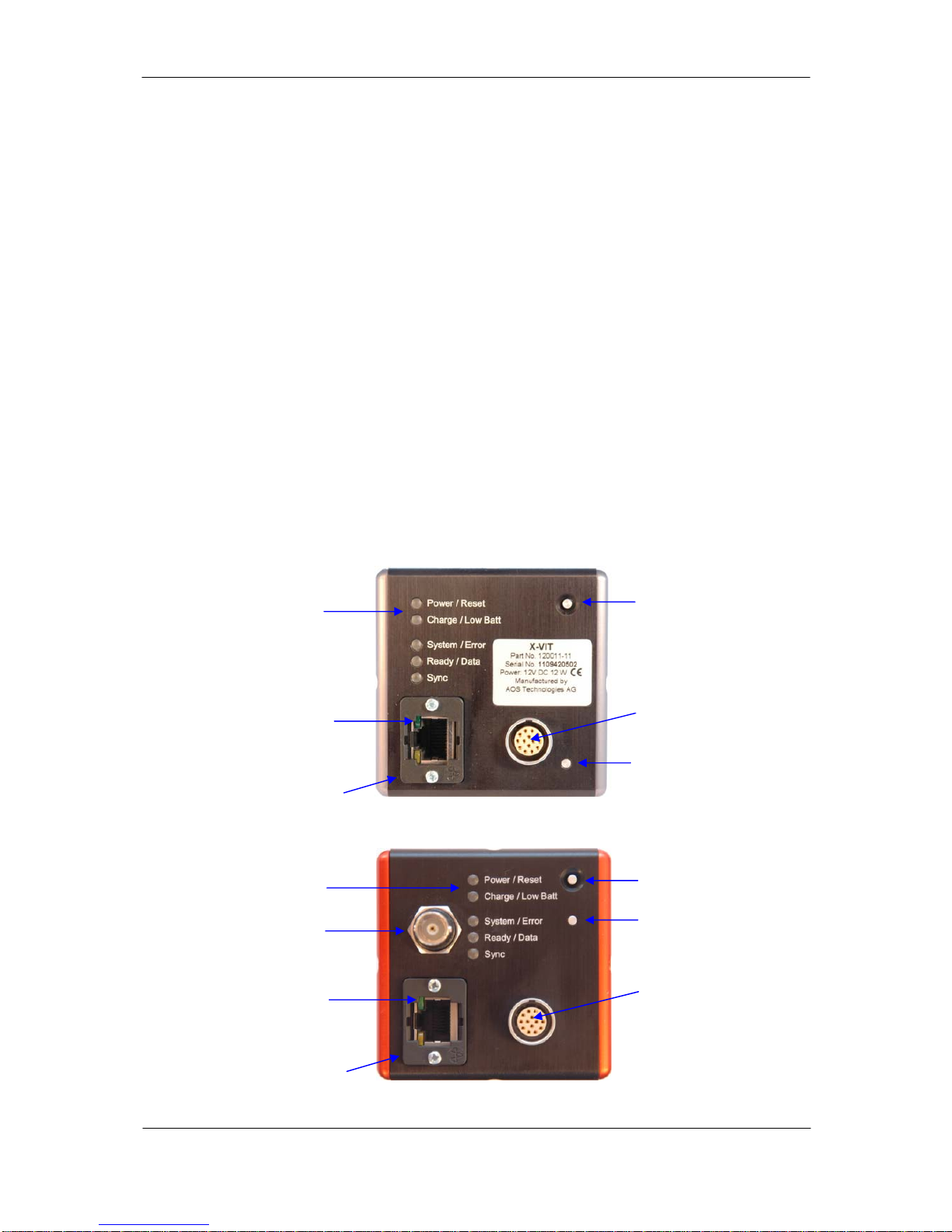
3.1.1 The camera rear panel .....................................................................................................9
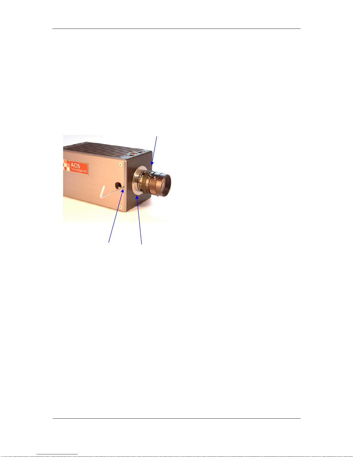
3.1.2 The camera front panel ..................................................................................................10
3.1.3 Status LED’s...................................................................................................................11
3.1.4 Data Interface LED (part of Ethernet Connector)..............................................................14
4OPERATION MODES........................................................................................................ 15
4.1.1 Sleep mode....................................................................................................................15
4.1.2 Ready mode...................................................................................................................15
4.1.3 Pre-triggering mode .......................................................................................................16
4.1.4 Armed mode – Skip „Set-to-rec“ .....................................................................................16
4.1.5 Recording mode .............................................................................................................16
5SYSTEM SETUP............................................................................................................... 17
5.1.1 Scope of supply .............................................................................................................17
5.1.2 CF interface ...................................................................................................................18
5.1.3 SDI or analog video interface .........................................................................................18
5.1.4 I/O Channels..................................................................................................................18
6MULTI CAMERA SETUPS .................................................................................................. 19
6.1.1 Multi camera systems without frame synchronization.......................................................19
6.1.2 Frame synchronisation ...................................................................................................20
6.1.3 Multi camera systems with frame synchronization (version 1) ..........................................21
6.1.4 Multi camera systems with frame synchronization (version 2) ..........................................22
6.1.5 Multi camera systems with frame synchronization (version 3) ..........................................23
7MAINTENANCE............................................................................................................... 25
7.1.1 Lenses...........................................................................................................................25
7.1.2 Battery ..........................................................................................................................25
7.1.3 Cleaning the AOS High Speed Camera Infrared filter........................................................25
8TROUBLESHOOTING ....................................................................................................... 26
9APPENDICES.................................................................................................................. 27
Copyright AOS Technologies AG Page 2 of 32

AOS High Speed Cameras Version 2.12
Description of external input and output signals.................................................................... 27
SPECIFICATIONS ..................................................................................................................28
Limited Liability.................................................................................................................. 30
10 OPTIONS AND ACCESSORIES ........................................................................................... 31
10.1.1 Trigger Breakout Box......................................................................................................31
10.1.2 I/O Breakout Box ...........................................................................................................31
10.1.3 Motion Analysis .............................................................................................................31
Copyright AOS Technologies AG Page 3 of 32

AOS High Speed Cameras Version 2.12
For information please contact us at:
AOS Technologies AG
Taefernstrasse 20
5405 Baden – Daettwil, Switzerland
Tel: +41 56 483 3488
Fax: +41 56 483 3489
Web
www.aostechnologies.com
info@aostechnologies.com
Please also refer to your AOS Technologies representative in your area.
List of manual revisions
Rev Date Release notes
1.0 Manual
2.00 9.10.2006 Manual, addition with X-PRI
2.01 X-EMA special 19.10.2007 Manual, changes for X-EMA
2.10 26.02.2008 Manual, additions for SDI interface
2.11 30.05.2008 Manual, IRIG-B specifications added
2.12 10.11.2009 Manual, information on S-Series cameras
Copyright
The information in this manual is subject to changes without any prior notice. AOS Technologies makes no warranty of
any kind with regards of the information provided herein. This limitation includes but not limits to implied warranties of
merchantability and fitness for a particular purpose AOS is under no circumstances liable for errors contained herein nor
for incidental or consequential damages from the furnishing of this information No part of this manual may be
photocopied or in any other means copied unless a written consent of AOS Technologies explicitly allows such
procedures.
Congratulations! With purchase of an AOS Technologies AG high speed camera system you have acquired a versatile, reliable
product allowing you to record high speed sequences in a very convenient way. The advanced and self contained digital camera
system provides a maximum in user friendliness and assists you in getting the results while others try.
Copyright AOS Technologies AG Page 4 of 32

AOS High Speed Cameras Version 2.12
Introduction
CONGRATULATIONS! By purchasing an AOS High Speed Camera high-speed digital imaging system, you
have acquired a versatile, future oriented, self-contained digital camera system. AOS Technologies AG
has combined advanced camera features with an easy to use software to create a solution for your
high-speed recording needs. The intent of this manual is to provide the information required for a
smooth operation of AOS High Speed Camera
General description of AOS High Speed Camera
AOS High Speed Camera is a high-speed camera capable of record and store data in it’s built in
camera memory. The rechargeable battery allows operation of up to 30 minutes in recording mode
and allows data buffering of up to 1h.
Unpacking / Check of completeness
Unpack your camera from its transport box and check if all accessories are complete
Standard scope of delivery is:
Qty Description
1 AOS High Speed Camera
1 Power/Trigger cable 0.5m
1 Power Supply incl. Power cable for EU- and US-mains plugs
1 CAT6 Data cable 5.0m
1 CD with AOS High Speed Camera operation Software and Camera manual
(pdf file)
Standard scope of delivery may vary from model, territory and distributor.
Copyright AOS Technologies AG Page 5 of 32

AOS High Speed Cameras Version 2.12
1Connecting the camera to a PC
Prior the first use of your new AOS high speed camera, certain steps need to be followed for a
successful start.
1.1.1 Visual inspection
Unpack the camera and visual inspection. Check for any visible damages.
1.1.2 Battery charging
Your AOS highspeed camera features a built-in, re-chargeable battery. Prior its first use, as well as
prior any recording session, make sure the battery is fully charged. This is also recommended if you
have your high speed camera always connected to power as the built-in battery will protect the image
memory against power failures and power losses.
Connect your AOS high speed camera to power following these steps:
-switch off your camera
-connect the Power/Trigger cable (included with each camera) to the cameras I/O connector at
the rear
-connect the 2-pin LEMO connector of the Power/Trigger cable to the DC-Adapter (included
with each camera)
-Connect the DC-Adapter to mains (100…240VAC)
-Check if the cameras “Charge” LED lights up in green
-Charging time is approx. 4 hours (if battery is fully discharged)
External power supply.
Also used to charge
battery
External trigger signal
(closing switch / TTL
low)
The input range of AOS High Speed Camera is 8 to 16VDC (24 to 36VDC for X-
EMA cameras). If applying more than 16VDC (36VDC for X-EMA) serious damages
of the camera results. Such damages are not covered by the warranty.
Copyright AOS Technologies AG Page 6 of 32

AOS High Speed Cameras Version 2.12
1.1.3 Switching-on and -off procedure
1- Switching on (standard) when camera is switched off
press “Power” push button shortly
wait until startup sequence has been completed (“System” LED comes to a rest)
2- Switching on (overwriting changed setup, start with factory presets)
press “Power” push button for more then 4 sec
release button and wait until startup sequence has been completed (“System” LED comes to a
rest)
3- Switching off (standard) when camera is switched on
press “Power” push button shortly
“Power / Reset” LED will indicate the shutdown sequence
4- Switching off (enforced shutdown) when camera is switched on
press “Power” push button for more then 4 sec
Camera shuts down without the normal procedure. This is only necessary and recommended if
the camera does not react on the standard switching off procedure (see par. 3) or is in a
“freak” position (i.e. all LED’s blinking)
Note that in case you switch off any S-Series or X-series camera it is imminent to
have the camera unpowered for min 30 sec. before switch on again. When
switching on the camera within 30 sec after power down some setting may not be
deleted due to camera internal power management reasons.
Note: When it is necessary to reset the camera, hold the reset button pressed for
a minimum of 1 sec. Otherwise faulty settings may be loaded.
1.1.4 Connecting the camera to a PC
Your AOS camera does not need a special or dedicated control device, often called “camera
controller” or similar. With its standard Gigabit Ethernet data interface, your camera can be simply
connected to any standard PC (Laptop or Desktop) or Ethernet-based LAN data network.
Follow the following steps to connect the camera to your PC
-install the included camera control SW (AOS Imaging Studio)
-Switch your camera on (see 1.1.3)
-connect the included CAT6 data cable to the camera and to the appropriate port on your PC
Copyright AOS Technologies AG Page 7 of 32

AOS High Speed Cameras Version 2.12
These rugged high speed cameras offer a special
data connector to securely lock the data cable to
the camera. Although standard CAT6 cables can
be used too, a secure cable lock is achieved by
using the included data cable with its cable lock.
These non-ruggedized high speed cameras offer a
standard data connector to accept standard CAT6
Ethernet data cables.
S-VIT & X-VIT / X-EMA S-MOTION & X-MOTION / X-PRI
Copyright AOS Technologies AG Page 8 of 32

AOS High Speed Cameras Version 2.12
2Installation of the Control Software and Camera drivers
Please refer to the “AOS Imaging Studio Manual” and “Installation guide”, also to be found on the
included CD
3Operation of the High Speed Camera
The operation is primarily done by using the included AOS Imaging Studio camera control software.
Therefore all functions and instructions how to operate the camera can be found in the “AOS Imaging
Studio Manual” (to be found as a pdf file on the included CD).
Please follow the manual carefully to execute all operations.
In case of uncertainties or questions, please do not hesitate to contact your AOS distributor or our
support engineers.
3.1.1 The camera rear panel
Power switch
Status LED’s
I/O Connector
Data IF LED’s
Reset switch
Data IF connector RJ45 Camera with standard interface
Reset switch
Power switch
Status LED’s
SDI or analog
video connector
I/O Connector
Data IF LED’s
Data IF connector RJ45
Camera with video interface
Copyright AOS Technologies AG Page 9 of 32

AOS High Speed Cameras Version 2.12
3.1.2 The camera front panel
The “Ready / Data” status LED duplicates the same LED on the camera back panel (see 3.1.3 for
explanation)
Your high speed camera has been carefully adjusted for accurate back focus alignment to make sure
your lenses can be precisely focused all the way between close up and infinity.
However, if you use special (close up) optics or any non-standard lens, it might be necessary to re-
adjust the backfocus by following these steps:
Copyright AOS Technologies AG Page 10 of 32
A
djusting the backfocus:
Ready / data LED
- loose Allen screws to free focus ring on both
sides of the camera
- set lens to infinity and its iris to maximum
(lowest f-stop number, i.e. 1.4)
- aim at an object near the horizon
- adjust focus ring until distant object is in focus
- set lens to 2m
- aim at an object in exactly 2m distance
(newspaper on a wall)
- adjust focus ring until object is in focus
- repeat steps 1 and 2 until close and distant
objects can be focused correctly
2mm Allen
screw
Focus ring

AOS High Speed Cameras Version 2.12
3.1.3 Status LED’s
Your high speed camera has a number of Status LED’s on its back panel to indicate operation modes
and error codes. The LED’s indicate
-operation mode
-battery status
-power status
-data transfer information
-error codes
Explanation
LED off
LED permanently green
LED permanently red
LED flickering green
LED flickering red
LED flickering green and red
Power / Reset LED
Remarks
Camera switched off
Camera on
(normal mode)
Camera has been switched on normally by the power
push button
Camera on
(Factory reset mode)
Power push button has been pressed for 4 secs.
Camera starts in the Factory Reset Mode and resets
all parameters to Factory Default values before
camera switches off
Camera is switching off
(Power off mode)
Camera has been switched off by the power push
button. Camera operating system shuts down.
Camera reset
(Reset mode)
Camera has been reset. Operating system starts.
Image data remain unchanged. When the reset mode
is completed, camera changes to normal mode
Copyright AOS Technologies AG Page 11 of 32

AOS High Speed Cameras Version 2.12
Copyright AOS Technologies AG Page 12 of 32
Charge / Low Batt LED
Remarks
Battery is fully charged
Battery is charging
Low battery capacity
Battery needs to be charged immediately
System Error LED
Remarks
Booting error
Switch off camera (power switch) or
reset camera (reset switch).
If camera does not start, contact your AOS partner
Start up sequence
Camera will be in normal mode within seconds
Start up sequence completed
(normal mode)
Camera error
Switch off camera (power switch) or
reset camera (reset switch).
If camera does not start, contact your AOS partner
Note: When it is necessary to reset the camera, hold the reset button pressed for
a minimum of 1 sec. Otherwise faulty settings may be loaded.

AOS High Speed Cameras Version 2.12
Ready / Data LED
Remarks
Normal mode
Camera ready
Camera is ready to record
Pre-trigger buffer gets filled
with image data
Camera records and fills image data in ring buffer
Camera in pre-trigger mode
Camera is waiting to receive the trigger signal to start
recording
Camera triggered
Camera continues recording until image memory is
full
Image data download
Image data is being downloaded to PC or internal CF
memory
Download completed
Download of image data completed.
Next recording can be started
Sync LED
Remarks
No external sync
External sync signal received
External sync signal controls the image clock
Sync error
Sync error: actual frame rate is lower then the
external clock. Check camera settings
Copyright AOS Technologies AG Page 13 of 32

AOS High Speed Cameras Version 2.12
3.1.4 Data Interface LED (part of Ethernet Connector)
Upper LED
Lower LED
Upper LED:
Sync LED
Remarks
No link established
Link established
Transfering data
Lower LED:
Sync LED
Remarks
Transfer speed:
10/100 Mbits/sec
Transfer speed:
1000 Mbits/sec
Copyright AOS Technologies AG Page 14 of 32

AOS High Speed Cameras Version 2.12
4Operation Modes
AOS High Speed Camera basically has 5 operation modes that allow an efficient power management.
Understanding the functionality of the camera is essential for best operation of the camera.
Copyright AOS Technologies AG Page 15 of 32
4.1.1 Sleep mode
In the sleep mode the camera internally shuts down all tasks not required for data security,
communication and battery charging. Recording in the camera buffer are retained and may be
accessed again. Lowest power consumption assures data security in the RAM buffers for 1 hour. By
receiving a command the camera goes automatically into READY mode.
The duration of how long data are retained in RAM memory of the camera is
depending on the capacity of the built in battery. The battery assures 1 hour of
data security under standard conditions. Battery time is affected by temperature,
age of battery and humidity that can result in a substantial reduction of the time
which data can be retained in the RAM.
4.1.2 Ready mode
In this mode the camera runs at full speed but having the sensor only active for preview modes. In
this mode the camera is being parameterized and setting of the scene is performed. By clicking the
green button the camera goes into the READY mode. If in the option “Skip Set-to-rec” is selected the
camera goes directly into recording mode as selected. A message will appear to acknowledge the
overwriting of the buffer.
Mode:
Output signals:
Preview /
Idle Ready Pre-
triggered Recording
Input signals
/ commands: Set ready Set-to-rec Trigger
„armed“
„triggered“

AOS High Speed Cameras Version 2.12
4.1.3 Pre-triggering mode
When a pre-trigger time is selected the camera may go from READY mode into PRE-TRIGGERED mode
by either clicking on the white button icon on the screen or by using the external connector to supply
a PRE-TRIGGERING signal from an external source. Once in PRE-TRIGGERED mode the amber and red
light on the back of the camera start flashing.
When you put the camera into PRE-TRIGGERED mode via the PC, be sure you
have not disconnected the Ethernet link. The Ethernet link may be disconnected
after the camera is in PRE-TRIGGERED mode.
4.1.4 Armed mode – Skip „Set-to-rec“
If in the camera control software the option “Skip Set-to-rec” is selected the camera goes directly into
the RECORDING mode as selected. For data security a message will appear to acknowledge the
overwriting of the buffer.
4.1.5 Recording mode
In this mode the camera finishes the ongoing recording and then awaits access (reconnection of the
Ethernet link). The camera automatically goes into a power save mode after the recording.
As long as unsaved data is in the camera (no access via Ethernet after a
recording) the red LED is constantly on. After accessing the camera via Ethernet
this LED goes out.
Copyright AOS Technologies AG Page 16 of 32

AOS High Speed Cameras Version 2.12
5System setup
Your AOS highspeed camera with its standard Gigabit Ethernet Data interface can be used in many
different configurations, depending on the application you have.
5.1.1 Scope of supply
Your AOS high speed camera is delivered with the following:
-high speed camera (1)
-power supply 12VDC or 24VDC for X-EMA (not shown)
-Power / Trigger Adapter cable 0.5m (2)
-Ethernet data cable (3)
Copyright AOS Technologies AG Page 17 of 32
1
2
3
Add-Ons
Add-ons are extension modules especially designed for your AOS high speed camera and will extend
the functionality of your camera for your specific applications.
Some add-ons have to be purchased with the camera (i.e. the CF interface), others may be purchased
at any time (i.e. Firm- and Software add-ons). Please contact your distributor for more information.

AOS High Speed Cameras Version 2.12
5.1.2 CF interface
The widely used non-volatile Compact Flash memory cards – as used in digicams and other products –
offer a most convenient way to have your image data downloaded from the camera memory. Instead of
downloading the image data via the Gigabit Ethernet data interface to your PC’s harddisk, the image
data gets downloaded to the CF memory card inserted into your camera.
As the CF interface includes also hardware inside the camera (easily to be
identified by the “slot” on the left camera side plate), this add-on has to be
either ordered together with the camera, or your camera has to be returned to
AOS for a factory modification.
5.1.3 SDI or analog video interface
The AOS High Speed cameras are available with a video output as an option. This video output is
either available in digital SDI or analog CVBS format and must be ordered together with the camera.
The specification of the video output is as follows:
SDI (Serial Digital Interface)
Standard Definition Video (SDTV) – 625 or 525 lines
Coding according ITU-R BT.601-6 (4:2:2 YcbCr component video)
625 lines video (SDTV 576i)
Active resolution: 720x576
Image frequency: 25Hz (50Hz interlaced)
525 lines video (SDTV 480i)
Active resolution: 720x480
Image frequency: 29.97Hz (59.94Hz interlaced)
Analog CVBS (Composite Video Baseband Signal)
NTSC-M (525 lines / 60Hz)
PAL-B/D/G/H/I (625 lines / 50Hz)
Limitations
The maximal resolution supported on the NTSC-M video standard is limited to 1280x960 in Imaging
Studio. Higher vertical resolution leads to image distortion and artifacts.
The SDI and Analog CVBS Video output is dedicated as an adjustment aid for an
external monitor for setting up the aperture and focus of the camera lens.
The image quality of the SDI and Analog CVBS Video output is not equal to the
quality of the digital image displayed in Imaging Studio.
5.1.4 I/O Channels
Each AOS High Speed Camera features digital I/O-Channels to either accept external signals (i.e.
positioning switch) or to provide a digital output signal (i.e. “trigger out”).
The AOS High Speed Camera S-PRI & X-PRI offer 1 digital I/O-channel as a
standard. With “Option 4”, 3 additional channels can be added (making a total of
4 channels).
Copyright AOS Technologies AG Page 18 of 32

AOS High Speed Cameras Version 2.12
6Multi camera setups
The GigE data interface of the AOS high speed cameras, together with the AOS Imaging Studio
software, allows connecting and using more then one high speed camera to one control PC.
Camera models S-PRI / X-PRI are by definition “one-camera-systems”, meaning
one camera runs on one PC. With “Option 5”, any S-PRI / X-PRI can be upgraded
to a multi-camera system, similar to S-MOTION / X-MOTION S-VIT/ X-VIT and X-
EMA.
6.1.1 Multi camera systems without frame synchronization
If cameras have to, or can, be operated independently (without frame synchronization), the cameras
can simply be connected using their GigE data interface and CAT6 cables. To bridge longer distances,
commercially available GigE network components like Bridges, Hubs and Routers can be used.
The trigger signal has to be provided to each individual camera using 2-wire trigger cables and / or
AOS trigger cables.
Copyright AOS Technologies AG Page 19 of 32

AOS High Speed Cameras Version 2.12
6.1.2 Frame synchronisation
For accurate motion analysis, cameras have to be synchronized to make sure each frame starts at the
very same time to avoid time slip:
Copyright AOS Technologies AG Page 20 of 32
Time slip due to failing synchronization
FrameFrame FrameFrameFrame
Cam 2:
Clock 1‘000.002Hz Frame Frame FrameFrame
Frame
Tri
gg
er T0
Cam 1:
Clock 1‘000.000Hz
Cam 2:
Clock 1‘000.000Hz
Frame Frame
FrameFrame FrameFrameFrame
FrameFrame Frame
Cam 1:
Clock 999.998Hz
Tri
gg
er T0
Phase lock frame synchronization
Other manuals for X-PRI
2
This manual suits for next models
6
Table of contents