AOTAI ASP-8KTLC User manual

Grid-tied PV Inverter
ASP-8/10/12/15KTLC
Operating Manual

ASP-8/10/12/15KTLC
1
Contents
1. Overview.................................................................................................3
1.1 Use of this manual........................................................................... 3
1.2 Symbols........................................................................................... 3
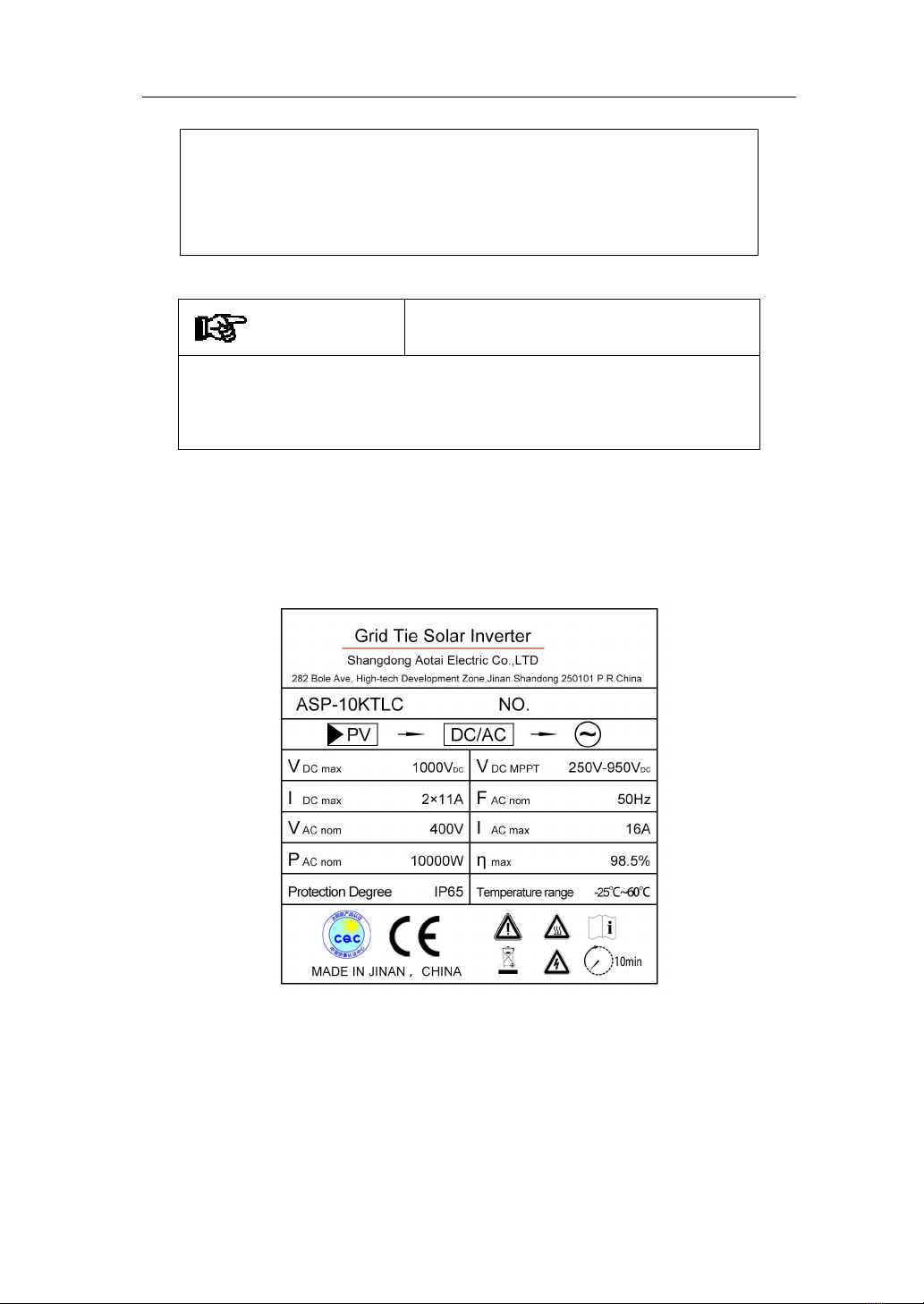
1.3 Nameplate........................................................................................ 4
2. Delivery..................................................................................................... 5
2.1 Scope of Supply............................................................................... 5
2.2 Product Acceptance..........................................................................6
3. Description.................................................................................................7
3.1. Brief Introductions..........................................................................7
3.2 General Introduction........................................................................ 9
4. Installation................................................................................................11
4.1 Installation Procedure.................................................................... 11
4.2 Installation Preparation.................................................................. 12
4.3 Mechanical Installation..................................................................16
4.3.1 Safety.................................................................................. 16
4.3.2 Dimensions......................................................................... 17
4.3.3 Installation.......................................................................... 18
4.4 Electrical Connection.....................................................................20
4.4.1 Electrical Connection Requirements.................................. 20
4.4.2 Wire Connection................................................................. 22
4.5. Inverter Commissioning............................................................... 27
4.5.1 Check before Commissioning.............................................27
4.5.2 Commissioning................................................................... 28
4.5.3 Shutdown............................................................................ 28
5. Monitoring............................................................................................... 29
5.1 Overview........................................................................................29
5.2 LCD Display Panel........................................................................ 30
Thank you for choosing AOTAI non-isolated
on-grid PV inverter. In order to ensure your
safety and proper use, please read the manual in
details before using. Thanks for your
cooperation!

ASP-8/10/12/15KTLC
2
6. Operating guide........................................................................................31
6.1 Working modes.............................................................................. 31
6.2 Power generation process.............................................................. 33
6.3 Disconnect from grid..................................................................... 33
7. Maintenance and Repair.......................................................................... 33
7.1 Maintenance...................................................................................34
7.2 Troubleshooting............................................................................. 34
8. Appendix...............................................................................................36
8.1 Technical Parameters..................................................................... 36
8.2 Quality Assurance.......................................................................... 38

ASP-8/10/12/15KTLC
3
1. Overview
1.1 Use of this manual
This manual mainly introduces installation, operating and maintenance of
ASP-8/10/12/15KTLC and related technical parameters. It is suitable for
people who install the inverters and do other related jobs. Readers need to
have some knowledge of electric, electrical wiring and mechanics. Before
installing this product, please read this manual carefully, and put it in a
suitable place, so as to ensure that relevant personnel of installation and
operation can easily get it.
1.2 Symbols
Please strictly follow below safety rules when installing and operating.
DANGEROUS
This symbol means there is high level of potential danger. If do
not listen to this warning, it might directly cause serious injury to
human.
WARNING
It tells people that there is medium level of potential danger. If not
listen to this warning, it might directly cause serious injury to
human.
CAUTION

ASP-8/10/12/15KTLC
4
It means that there is low level of potential danger. If not listen to
this warning, it might cause personal injury or serious financial
loss.
ATTENTION
It means there is potential risk. If not listen to this warning, it
might cause financial loss.
1.3 Nameplate
Take ASP - 10 KTLC for example

ASP-8/10/12/15KTLC
5
2. Delivery
2.1 Scope of Supply
There are following items in the packing box, as shown in Table 2-1.
Please check in time after receiving the products.
Order
Name
NO.
Note
1
PV on-grid inverter
1
2
Operating manual
1
3
Product qualification certificate
1
4
Fixed plate
1
5
Factory inspection report
1
6
PV cable connector
2/3
Male/female cable connector, 2/3
for each
7
Expansion bolt
5
Used for fastening the fixed plate
8
Cross recessed hex bolt
2
Used for fastening machine and
the fixed plate
9
Hexagon bolt
5
Used for fastening the fixed plate
10
Flat washer
5
Used for fastening the fixed plate
11
Spring washer
5
Used for fastening the fixed plate
Table 2-1: Scope of supply

ASP-8/10/12/15KTLC
6
2.2 Product Acceptance
Although we have carefully tested and inspected the products before
delivery, but there might be damages during transport. So, please check
them when sign for them. If there is any damage, please contact the
shipping company or directly contact AOTAI. Please provide photos of
the damaged parts, and we will provide the best service as fast as
possible.

ASP-8/10/12/15KTLC
7
3. Description
3.1. Brief Introductions
On-grid PV power generation system usually is composed of solar panels,
junction box, inverter, ammeter and power grid. The core of the system is
PV grid-connected inverter. The sunshine irradiates on the surface of the
solar panels, solar panels output DC, converted by inverter, then output
AC of the same frequency and phase with the grid, and then feed into the
grid.
ASP-8/10/12/15KTLC in application of PV power generation system is
shown in Figure 3-1.
Solar Inverter
PV. Arrays
Meter
Utility Grid
Fig 3-1 Grid-connected PV Power Generation System
Sun

ASP-8/10/12/15KTLC
8
Product performance
Transformerless, highest efficiency is 98.5%
Wide input voltage, MPPT efficiency is 99.9%
Two way independent MPPT control to deal with different
installation angles, enhance power generation
Active and passive anti-islanding protection technology
Comprehensive protection, higher reliability
IP65 Outdoor design, suitable for harsh environment
RS485、WIFI、GPRS multi-communication interface, user friendly.

ASP-8/10/12/15KTLC
9
3.2 General Introduction
Appearance and interface
Appearance of ASP-8/10/12/15KTLC (take ASP-10KTLC for example) is as
shown in Figure 3-2. Its external interface is in the bottom of the machine and is
composed of PV input port +, PV input port-, communication port, DC switch.
Please refer to Figure 3-3 and Table 3-1 for details.
Fig 3-2 Appearance of ASP-10 KTLC

ASP-8/10/12/15KTLC
10
No.
Name
Description
1
PV input port +
Inverter’s DC input port, connect
with + port of solar panels.
2
PV input port -
Inverter’s DC input port, connect
with – port of solar panels.
3
DC input port
8-10KTLC inverter is Nylon
stopper head; 12-15KTLC is DC
input terminal.
4
DC switch
Electric cut off between inverter
and solar panels
5
WIFI/GPRS/RS485
Connect inverter with PC through
this port for remote monitoring
6
AC output port
Connect with phase A, B, C and
wire N of the grid through the
breaker, connect ground wire to
the ground
7
Earthing bolt
Connect with ground
Table 3-1: External Interface
Fig 3-3: External Port

ASP-8/10/12/15KTLC
11
4. Installation
Please carefully read below installation guide for ASP-8/10/12/15KTLC.
4.1 Installation Procedure
Start
Preparations
Mechanical installation
Electrical connections
Check after installation
Commissioning with power
on
Finish
Fig 4-1 Installation procedure

ASP-8/10/12/15KTLC
12
4.2 Installation Preparation
●Check whether there is damage during transport
Although we have carefully tested and inspected the inverter before shipping,
there might be damage during transport. So please check them before installation.
If there is any damage, please contact the shipping company or directly contact us.
Please provide photos of the damaged part. We will provide the best service at
fast as possible.
●Tools for installation
The following installation tools and parts are needed.
Spanner
Electric impact drill
Cross screwdriver
M4 Allen wrench
Megameter & Multimeter
● Basic Installation requirements
The protection level for this series is IP65. Below are the basic requirements.
Can be installed outdoors
In order to prolong the service life of the inverter, do not put the inverter
directly under the sunshine, rain and snow. A place with shelter will be better
for installation.

ASP-8/10/12/15KTLC
13
Installation place should not shake.
Installation height is better to make the LCD at the same level with people’s
eye so as to make it convenient to operate on the LCD.
Requires good ventilation
The ambient temperature should be between -25℃~+60℃

ASP-8/10/12/15KTLC
14
ATTENTION
Ambient temperature range should be -25℃~ +60℃. If out of
the range, it will affect power generation.
Installation environment needs to be clean;
The inverter needs to be installed uprightly, and cannot be placed
horizontally or upside down, or tilted.
Enough space surrounding the inverter is needed to ensure good heat
dissipation.

ASP-8/10/12/15KTLC
15
Multiple inverters can be installed side by side, and multiple rows of
inverters need to be installed staggered to facilitate heat dissipation.
Do not install the inverter in the place where children can touch so as to
avoid scald or electric shock. Temperature of some parts of the inverter(e.g.,
radiators) will be higher during working
Inverter’s installation location (wall or holder) should withstand weight of
inverter for a long time.

ASP-8/10/12/15KTLC
16
DANGER
Don't put inverter together with inflammable, explosive goods.
CAUTION
During working, the inverter is of high temperature. Please do
not touch it!
4.3 Mechanical Installation
4.3.1 Safety
Touch any part of the inverter may cause deadly injury. DC side voltage of the
inverter is up to 1000V, and AC side 450V. All installation and wire connection
need to be done by professional electric or mechanical engineers.
WARNING
The inverter must be installed by professional engineers.
Note!
1. When installing, don't touch any other parts in the machines except wire
connector.
2. All electrical installation must comply with local electrical installation
standards.

ASP-8/10/12/15KTLC
17
3. Maintenance must be done by professional people.
4. Grid connection of this inverter must be allowed by local power supply
departments.
5. When installing solar panels during the day, please cover the panels with
lighttight materials. Otherwise, there will be very high voltage at the panel and
cause personal danger.
WARNING
DC input voltage should not be higher than 1000 V. Otherwise, it
might cause permanent damage to the equipment and other loss.
4.3.2 Dimensions
In order to make it convenient for mechanical installation, we provide the size. As
shown in figure 4-2.

ASP-8/10/12/15KTLC
18
Figure 4-2 Inverter size
4.3.3 Installation
Fixed plate and fasteners like expansion bolts are used to install the inverter
vertically on the wall or metal stents. Bolts are M8 x 30, as shown in figure 4-3.

ASP-8/10/12/15KTLC
19
Figure 4-3 Fixing plate mounting hole position
If install the inverter on concrete wall, firstly mark drill hole on the wall according
to fixed plate size, and drill at marked locations, then fix plate on wall with M8*30
expansion bolts, and then hang the machine on the plate.
This manual suits for next models
3
Table of contents
Other AOTAI Inverter manuals
Popular Inverter manuals by other brands

CE+T Power
CE+T Power TSI MEDIA 2I user manual

Lenze
Lenze 8400 motec Series Mounting instructions

ABB
ABB PVI-5000-OUTD-US product manual

Kaco
Kaco blueplanet 50.0 TL3 Basic operation instruction

Furrion
Furrion Net-Zero FSPP95SA-BL instruction manual

Mitsubishi Electric
Mitsubishi Electric F800-E Series instruction manual