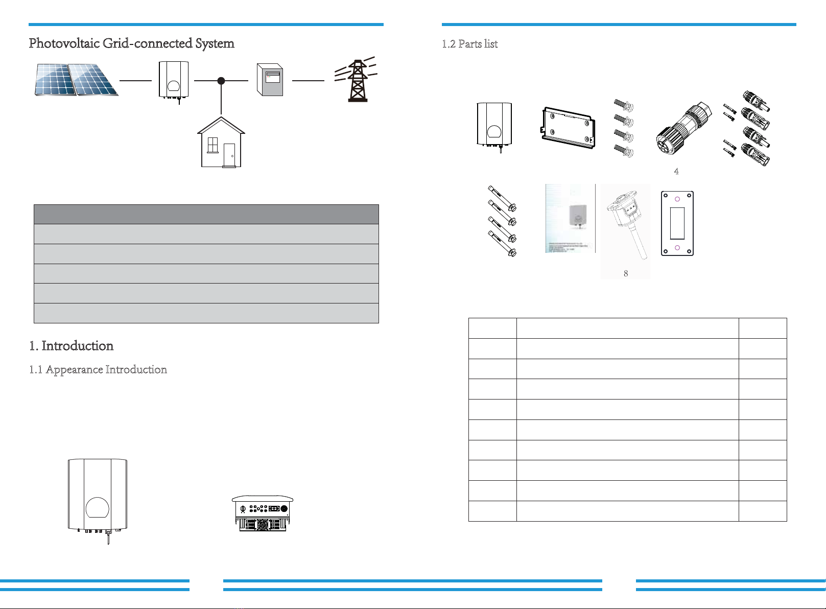
NOTE:
Sunlight shines on the panels will generate voltage, high voltage in series
may cause danger to life. Therefore, before connecting the DC input line,
the solar panel needs to be blocked by the opaque material and ensure that
the DC switch is 'OFF', otherwise, the high voltage of the inverter may lead
to life-threatening conditions.
Do not close the DC switch after the DC terminal is connected. Connect the AC terminal
to the AC side of the inverter, the AC side is equipped with three-phase AC terminals that
can be conveniently connected. Flexible cords are recommended for easy installation. The
specifications are as shown in sheet 5.2
1. Matching socket 2.Sleeve 3.Sealing core 4.Sealing nut
Pic 5.7 AC connector structure
The AC output connector is divided into three parts: matching socket, sleeve and sealing
sleeve, as shown in Picture 5.7, the steps are as follows:
Step 1 Remove the cable sealing ring and sleeve in sequence from the AC connector.
Step 2 Use strippers to strip the protective sheet and insulation layer of the AC cable
to the right length, as shown in Picture 5.8.
Step 3: Insert the cable (L1, L2, L3, PE) into the sealing sleeve and sleeve.
Step 4 Use the hexagon screwdriver, loosen the bolts of the socket in turn, and insert
each cable core into the corresponding jack, and set each screw. The connection hole
of AC connection terminal labeling is shown in Picture 5.9.
Warning:
Prohibit using a single circuit breaker for multiple inverters , prohibit the
connection of load between inverter circuit breakers.
Table 5.2 Cable information
Warning:
Be careful to distinguish the L1, L2,L3 and PE of the AC cables.
Outside cable(3+PE)20m Outside cable(3+PE)20m
5.2 DC input terminal connection
Specification
Model NITROX-12,15KW-3Ph-5G
30A/400V
NITROX-20KW/25KW-3Ph-5G
40A/400V
DiaCable item Cable
CSA
Cable
outer
dia
15~18mm2.5mm 6mm
AWG Dia Cable
CSA
10mm10 2.5mm
Cable
outer
dia
AWG
15~18mm 8
2 2
Breaker
Max cable
length
1
2
34
Pic 5.8 Strip AC cable
8~15mm
40mm
- 15 - - 16 -