DENRYO GD300 User manual

Sine Wave Power Inverter
GD300 Series
User’s Manual
Ver.1.01E

2
Table of Contents
1. Safety Instructions........................................................................3
2. General Information......................................................................4
3. GD300 Inverter Features.............................................................5
3-1 Specification...............................................................................................................5
3-2 De-rating Curve ..........................................................................................................6
3-3 Dimension...................................................................................................................7
3-4 Control Panel..............................................................................................................7
4. Installation and Wiring Connections.......................................8
4-1 Installation Guide .......................................................................................................8
4-2 Wiring Connections....................................................................................................8
4-3 Setting Confirmation................................................................................................10
4-4 How to Start Up ........................................................................................................10
5. Functions........................................................................................ 11
5-1 Change Settings.......................................................................................................11
5-2 The Indicators of setting during operation ............................................................12
5-3 The Protective Function...........................................................................................12
5-4 Remote Connector ...................................................................................................14
5-5 Optional Terminal.....................................................................................................14
6. LED Indicators ..............................................................................15
6-1 The LED Indicator in Normal Status .......................................................................15
6-2 The LED Indicators when Protective Function Activates .....................................16
7. Troubleshooting Guide...............................................................17
Sine Wave Power Inverter GD300 User’s Manual ©2017 DENRYO CO., LTD. All Rights Reserved. No parts
of this document may be reproduced in any form without the prior written approval of DENRYO CO., LTD.
©2017 DENRYO CO., LTD. All Rights Reserved.

3
1. Safety Instructions
This document contains the important safety and operating information for GD300 Inverter. To get most
out of the Pure Sine Wave Inverter, carefully read, follow this guide, and save these instructions. Pay
attention to the Safety Instructions and the CAUTION and WARNING statements found throughout the
manual and on the product.
Precautions During Installation
・To avoid the risk of electric shock and fire, ensure adherence to proper electrical wiring regulations. Do not
disassemble the GD300 Inverter.
・Do not expose the GD300 Inverter to rain, snow, dust or to the places with high humidity.
・Do not install the GD300 Inverter in the environments with high temperature, near a fire, or under sun
exposure directly.
・During the operation of GD300 Inverter, the temperature of the products may become higher. Be
careful while moving or removing the products.
・To avoid covering or obstructing the ventilation openings, do not to place any objects closer than 15
cm near the Inverter.
・To avoid overheating, do not place any stuff on the product.
・To connect with more than one battery, do use the same products of batteries from the same
manufacturer. Connecting different products of batteries at the same time is dangerous.
・Batteries generate explosive gases during normal battery operation. Never smoke or allow a spark or
flame in vicinity of battery.
・This equipment contains components which can produce arcs or sparks. To prevent fire or explosion,
do not install in compartments containing batteries or flammable materials.
CAUTION
Since the battery deteriorates over time, a maintenance on a yearly
basis is recommended. Replace the deteriorated battery to prevent the
hazard of fire.
WARNING
This sign indicates the following contents includes the important
information. The wrong order of handling may lead to the risk of death
or seriously injured.
CAUTION
This sign indicates the following contents includes the important
information. The wrong order of handling may cause damage to the
products and the surrounding stuff.
MEMO
This sign indicates the following contents includes the important
information of the manuals of functions which contains
the safety
instructions or the proper operation of the product.

4
2. General Information
GD300 Inverter is a pure sine wave inverter that converts DC voltage to AC since wave voltage. The output
waveform is as same as the sine wave of commercial power supply, of which the total harmonic distortion
is less than 3%. High efficiency circuit and switching control achieved 90% efficiency at rated load. Without
a built-in fan, the GD300 Inverter cools down by natural convection and has reduced the size of the
products as well as kept quiet during operation. Moreover, the GD300 Inverter is equipped with abundant
protective functions. Even the input polarity is reversed whereas the internal circuit does not be damaged.
With the capability of operating under the wide input voltage range, temperature range and to turn on or
off remotely, the GD300 Inverter could be used in various environments and applications.
Features
・Protecting the input reverse polarity by its internal circuit
・Fan-less quiet operation (natural convection)
・The wide range of operating temperature(-20~60℃)
・Switching output voltage/frequency easily by button
・Pure sine wave output (total harmonic distortion less than 3%)
・Light weight and thin design
・High efficiency (90% efficiency at rated load)
・Built-in remote-control function
・Easy understanding LED indicators
・Abundant protective circuit: Input voltage warning, shut down/Input reverse polarity/
Output voltage/Output short circuit/Overload/Overtemperature
・Buzzer ON/OFF, LED brightness switchable
・Wide input voltage range
・Input system voltage of 12V/24V/48V 3 lineup
・Input terminal cover for dust prevention
・Optional communication function (T. B. D.)
Safety and EMC Certified
Safety standards :EN60950-1:2006/A2:2013
Immunity standards :EN55024:2010
Emission standards :EN55032:2012, FCC class A Part15
FCC Requirements
This equipment has been tested and found to comply with the limits for a Class A digital device, pursuant
to part 15 of the FCC Rules. These limits are designed to provide reasonable protection against harmful
interference when the equipment is operated in a commercial environment. This equipment generates,
uses, and can radiate radio frequency energy and, if not installed and used in accordance with the
instruction manual, may cause harmful interference to radio communications. Operation of this equipment
in a residential area is likely to cause harmful interference in which case the user will be required to correct
the interference at his own expense.
5
3. GD300 Inverter Features
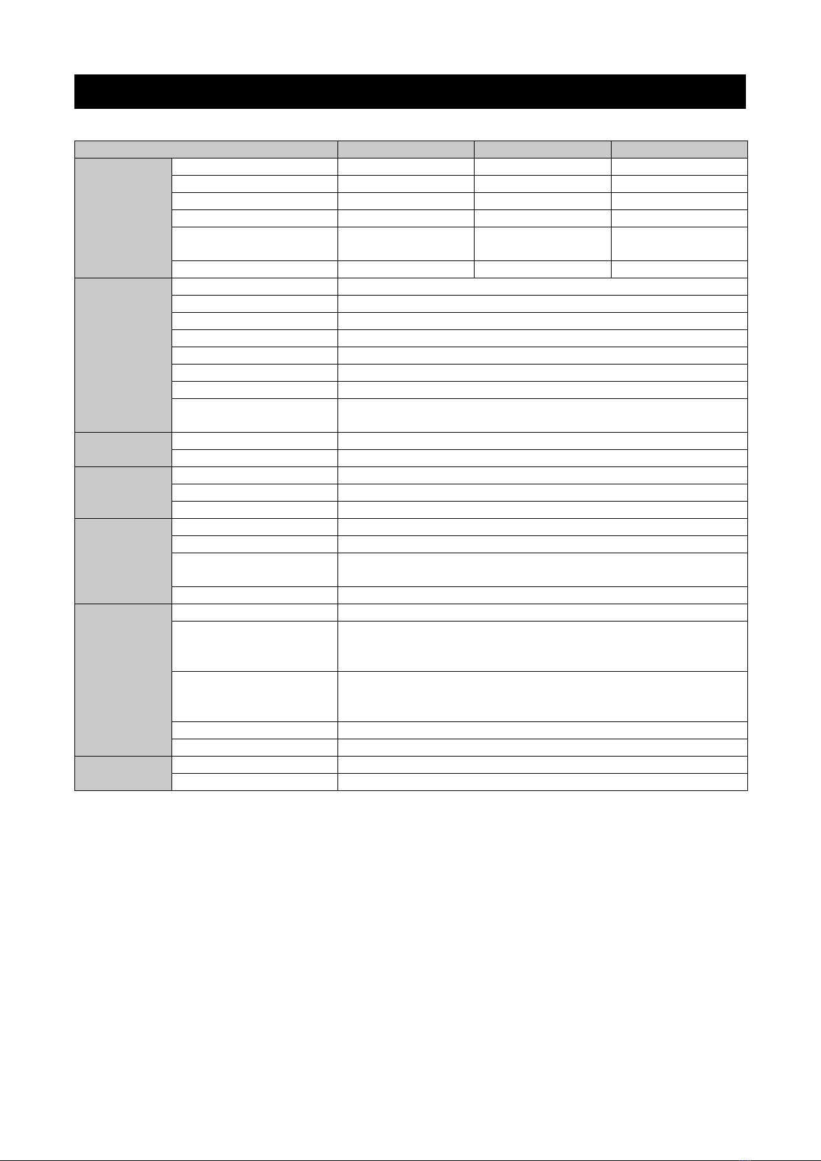
3-1 Specification
MODEL
GD300NA-112
GD300NA-124
GD300NA-148
Input
Battery Voltage
12V
24V
48V
Voltage Range*'
10.5~17Vdc
21~34Vdc
42~68Vdc
Current Range
20~32 A
10~16 A
5~8 A
No-load Current
0.7 A
0.4 A
0.2 A
Standby Mode
Consumption
8mA 7mA 5mA
Efficiency at Rated Load
90%
90%
90%
Output
Rated Power
300VA
Peak Power(3min.)
360VA, refer to 3-2 de-rating curve
Surge Power(3sec.)
420VA
AC Voltage
100 default, 110/115/120Vac, switchable
Frequency
50±0.1Hz default, 50/60Hz, switchable
Waveform
Sine Wave, <3%THD
Voltage Tolerance
±3.0%
LED indicators
Operating status, Battery voltage level, Output power level,
Protection function, Operation setting
Function
Remote-control
Output remote ON/OFF control terminal
Option terminal
six-position four-conductor (6P4C) modular jack
Protection
Input
UVP*², OVP*³, input reverse polarity
Output
OLP*⁴, SCP*⁵, output voltage error
Others
OTP*⁶, detect by internal temperature sensors
Environment
Operating Temperature
-20~+40
℃
at rated load, +60
℃
at 70% load, refer to 3-2 de-rating curve
Operating Humidity
20~90%RH non-condensing
Storage Temperature/
Humidity
-30~+70℃, 10~95%RH
Vibration
10~500Hz, 3G 10min./ 1cycle, 60mins. XYZ axes
Safety &
EMC
Safety Standards
Certified EN60950-1:2006+A11+A1+A12+A2
Withstand Voltage
Battery I/P-AC O/P: 3.0kVac
AC O/P–Ground: 1.5kVac
Battery I/P– Ground:1.5kVac
Isolation Resistance
Battery I/P–AC O/P: >1000MΩ/500Vdc/25
℃
/70% RH
ACO/P –Ground: >1000MΩ/500Vdc/25℃/70% RH
Battery I/P – Ground: >1000MΩ/500Vdc/25
℃
/70% RH
EMC Immunity
EN55024:2010
EMC Emission
EN55032:2012, FCC class A
Others
Dimension
234.0×146.5×44.0mm (L×W×H)
Weight
1.0kg
All parameters NOT specially mentioned are measured at 112:12Vdc, 124:24Vdc, 148:48Vdc input, 300VArated load, power
factor=1.0, 25°C of ambient temperature and under the default setting.
*' Tolerance of voltage: 112±0.5V, 124:±1V and 148:±2V.
*² UVP: Under Voltage Protection.
*³ OVP: Over Voltage Protection.
*⁴ OLP: Over Load Protection.
*⁵ SCP: Short Circuit Protection.
*⁶ OTP: Over Temperature Protection.

6
3-2 De-rating Curve
According to the system and environment that products are used in, the Inverter is still under the protection
of OLP or OTP even in the range of de-rating curve. Since this feature of the Inverter, please design the
system with more allowance. Refer to the graph above, the input voltage will be double under 24V model
and 4 times more under 48V model.
7
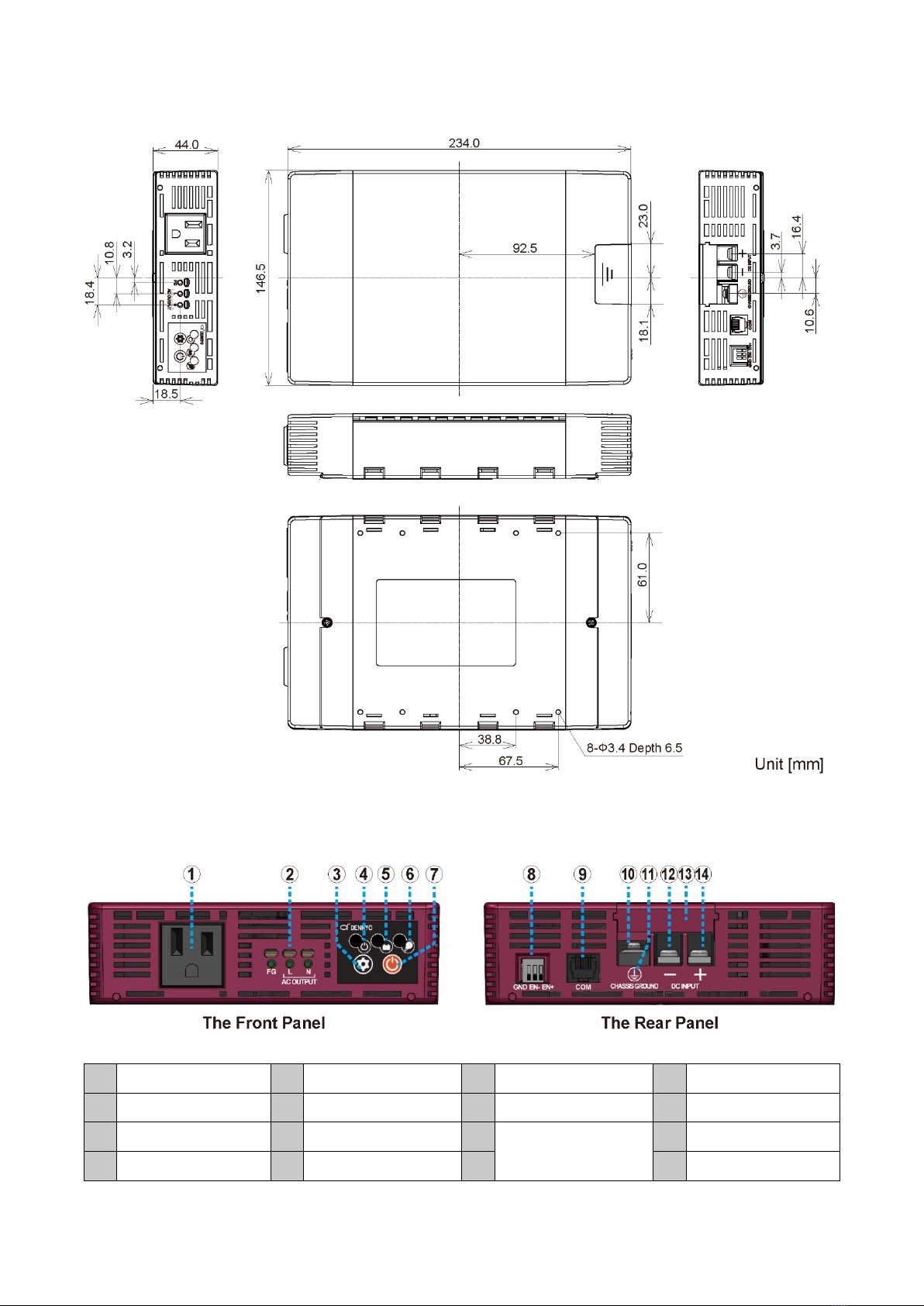
3-3 Dimension
3-4 Control Panel
○
1AC Outlet
○
2AC Output Terminal
○
3Setting Button
○
4Power LED
○
5Battery LED
○
6Load LED
○
7Power Button
○
8Remote Connector
○
9Optional Terminal
○
10 Grounding Terminal
○
11 Reversed Connection
Warning LED
○
12 Battery Input (-)
○
13 Terminal Cover
○
14 Battery Input(+)
8
4. Installation and Wiring Connections
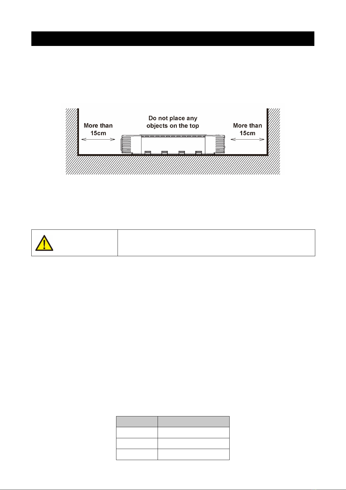
4-1 Installation Guide
Recommended installation location: Locate the GD300 Inverter on a flat place or rack with sufficient
strength. Avoid mounting in a dusty environment or a location with high temperature. Avoid using the
Inverter in a high temperature environment. For ventilation, do not mount any objects within 15 cm around
the inverter.
Figure 4.1 The example of installation
Recommended installation Regulation: Refer to 3-3 Dimension, there are 8 holes, Φ3.4mm, and depth
6.5mm, in the bottom of the Inverter, which could be utilized when installing the Inverter. It is recommended
to install the Inverter horizontally with the ground.
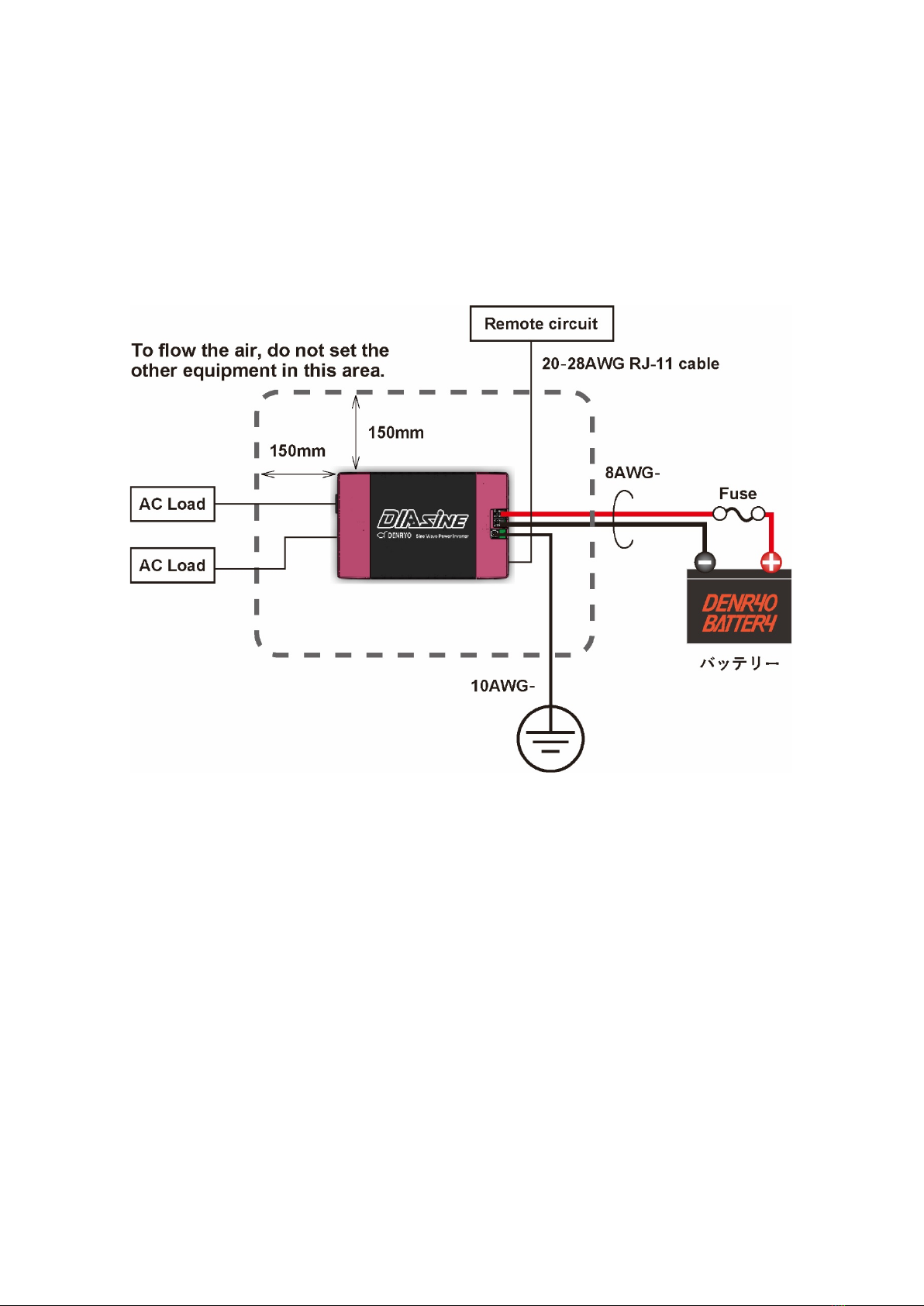
4-2 Wiring Connections
To make Battery wiring connections:
Remove the cover of the terminal on the rear side of GD300 Inverter, and wire it to the battery input terminal.
When removing the cover, slide while pushing the terminal cover toward the bottom. Mount a fuse in the
plus side wiring. Please refer to Table 4.1. to select the fuses based on the system. Please use suitable
wiring cable for power supply terminal. The screw size of battery input terminal is M4; the width of the
terminal is 9 mm. The cable size recommended to be used at rated load is 8 AWG; the torque
recommended for installation is 1.5 N · m. Using too thin cable may lead to overheating or ignition of cable.
The length of Battery wiring connection should be as short as possible that within 1.5 m is recommended.
Before continuing Battery wiring connection, check the power LED in front of GD300 is lighting orange.
Check the voltage of Battery if not lighting. Further, if the polarity of Battery is reversed, the reverse
connection warning LED near the grounding terminal in the rear of the GD300 Inverter lights red. Please
correct the polarity and check if the reverse connection warning LED is off.
Table 4.1 Fuse recommended
Model Current
112 Under 40A
124 Under 20A
148 Under 10A
CAUTION
Burns Hazard.
During operation, the temperature of GD300 Inverter will get higher. Be
careful not to touch it.

9
To make the grounding wire connection:
Connect from the grounding terminal in the rear of GD300 Inverter to the system is being used. The screw
size of the grounding terminal is M5; the width is 14mm. Please use solderless terminals, like R5.5-5S,
and fasten it with a screw. The cable size of 10AWG and torque 2.0 N・m is recommended.
To make load wire connection:
Connect the load from the AC outlet in the front of the GD300 Inverter or the AC output terminal. Choose
to use the cable with proper withstand voltage of AC output terminal when connecting the AC output
terminal. The VVF1.6 cable is recommended to be used here. It is connected by inserting the cable, which
is peeled off the cover, into the hole which is marked as AC OUTPUT on the front panel. The length to peel
off is around 15-20 mm and make the part which the cover has been peeled off could not be seen from
outside. Make sure that the wire connected to line (L) and neutral (N) is not short-circuited after connection.
When removing the cable, insert a flathead screwdriver in the oval hole above the cable insertion hole,
and pull the cable while pressing the flathead screwdriver to remove it.
DO NOT short the line and the neutral. Make sure the connection of the line and the neutral is correct in
your system when using both the outlet and the terminal of the Inverter.
Precautions about load:
Inverter is able to operate at most of loads under AC environment. However, even continuously suppling
300VA, there is a possibility that Inverter may not operate properly at some loads.
(1) An extremely large current, around 6~10 times more than at rated load, is required for Inverter
to startup at inductive load or the motor. The Inverter may not be able to startup normally in the
case. Please check the amount of peak current at load before choose Inverter.
(2) To ensure the complete startup of the Inverter, when connecting with a capacitive load or a
rectifier such as switching power supply, do not activate the load while the Inverter startup.
Alternatively, start up the Inverter with a smaller load and increase load afterward. If connecting
with more than two loads, please activate one load at once after the Inverter started up.
WARNING
Explosion Hazard
The short of Battery is very dangerous. Make the wire connection of
input terminal of GD300 Inverter before connecting the Battery.
CAUTION
Terminal damage.
Pressing the flathead screwdriver obliquely and strongly, the terminal
may be damaged.
WARNING
Shock Hazard
Make sure the core wire does not expose to the outside. Moreover,
when connecting the AC terminal, be sure to connect it without output
voltage.
10
To make Remote Connecter wire connection:
By the function of remote connecter in the rear of GD300 Inverter, it is able to turn the output ON/OFF
without pressing power button. Please refer to 5-4 Remote Terminal. The recommended size of cable for
remote connecter is 20~28AWG.
To make Optional Terminal wire connection:
The optional terminals in the rear of GD 300 Inverter uses a six-position four-conductor (6P4C) modular
jack to adapt to various application. Check DENRYO Official Website for more details.
Figure 4.2 System Wiring Diagram
4-3 Setting Confirmation
The default setting is output voltage 100Vac, output frequency 50Hz, buzzer ON, and normal mode of the
LED brightness. Pressing the setting button on the front panel to change the settings, refer to Chapter 5-
1 Change Settings. Settings remain even the Battery went out its power.
4-4 How to Start Up
Keep pressing the power button on the front side of the Inverter for around 1 second. Make sure the
Inverter is not under the protection mode by checking the LED indicators and turn on the load. The
introduction of LED indicators during operation please refer to Chapter 6 LED Indicators.

11
5. Functions
5-1 Change Settings
1. Connect with battery and set the GD300 Inverter to the standby status the power LED is lighting
in orange and other LEDs are off. Do not connect anything to AC outlet and AC output terminal.
2. Pressing the setting button in the standby status, the current setting will display around three
seconds. To change the setting, press and hold the setting button. Hold down the button for
about two seconds, and a buzzer sound* comes from the Inverter while only the power LED
indicator lights. Release the setting button and proceed to the next step.
*The Inverter does not sound once the buzzer is setting OFF.
3. Check the output frequency setting refer to Table 5.1. Press the setting button to select the color
of power LED until it matches the color of output frequency you choose. Hold the setting button.
4. Check the battery LED in the center of the Inverter is lighting. Refer to Table 5.1, press the setting
button to select the color of battery LED until it matches the color of output voltage you choose.
Hold the setting button.
5. Check only the load LED on the right side of the Inverter is lighting. Refer to Table 5.1, press the
setting button to select the color of load LED until it matches the buzzer setting ON/OFF and the
LED brightness you choose. Press and hold the power button for more than 2 seconds to
complete the settings and back to the standby status. If pressing and holding the setting button
before holding down the power button, the setting mode begins again from the output frequency.
6. Press the setting button. Check the Inverter is the same as the setting you chose.
Figure 5.1 The LED and settings button
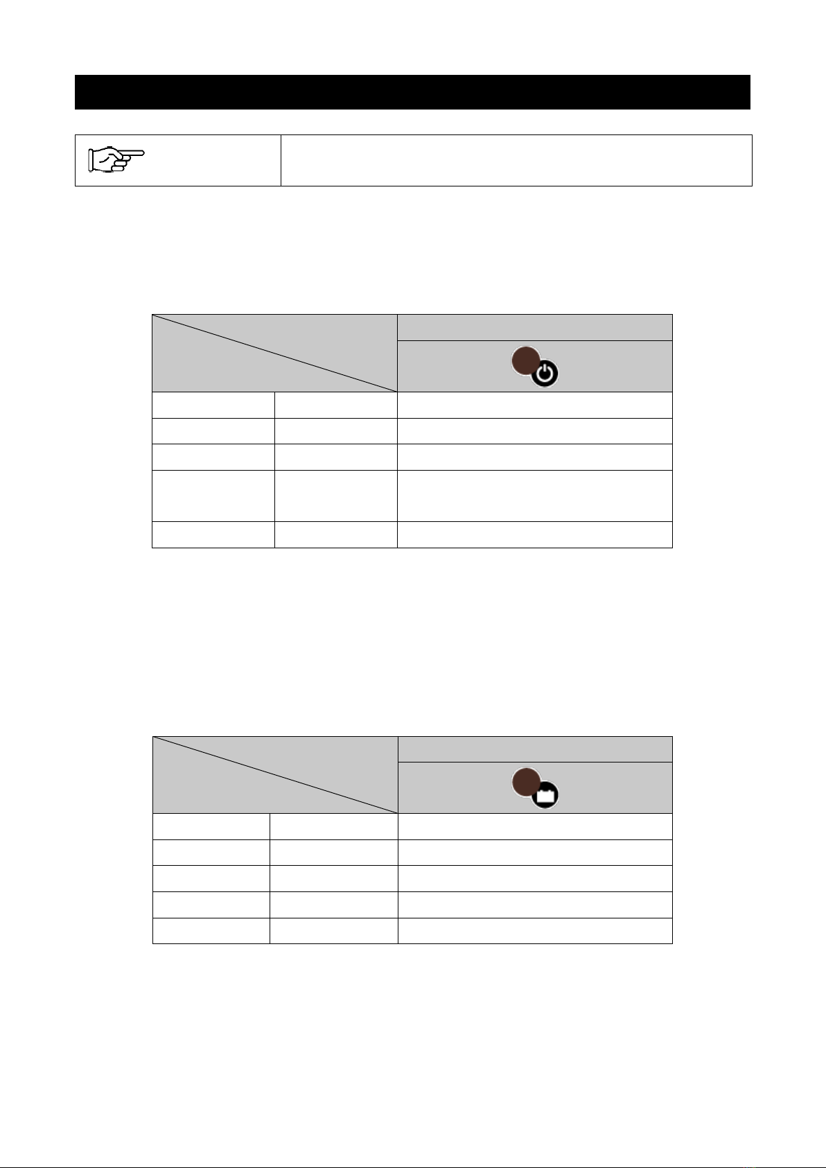
Table 5.1 The LED color of settings
LED
LED Color
Power LED Battery LED Load LED
Green
●
50Hz 100Vac Buzzer ON, bright LED
Yellow
●
60Hz 110Vac Buzzer ON, dark LED
Blue
●
- 115Vac Buzzer OFF, bright LED
Purple
●
- 120Vac Buzzer ON, dark LED

12
5-2 The Indicators of setting during operation
It is possible to check the current settings during operation by pressing the setting button, refer to Table
5.1. Settings are not able to be changed during operation.
5-3 The Protective Function
To prevent error operation, GD300 Inverter is equipped with the following functions.
A. Reversed battery polarity protection: The reverse warning LED near the grounding terminal in the
rear of GD300 Inverter lights red when the battery polarity is reversed. Please unconnected the
wire and connect with the correct polarity.
B. Battery low voltage protection: When the battery voltage falls below the value of low voltage
warning, the buzzer sounds three times consecutively around every 5 seconds. When the battery
voltage falls below the shut off value of low voltage, the Inverter automatically shuts off the output,
the buzzer sounds five times consecutively around every 5 seconds, and battery LED blinks red.
When the battery voltage reaches or exceeds the low voltage recovery value, it automatically
resumes output. The buzzer does not sound when the buzzer is setting OFF.
C. Battery overvoltage protection: If the battery voltage is higher than the overvoltage warning value,
the buzzer sounds three times consecutively around every 5 seconds. When the battery voltage is
higher than the shut off value of overvoltage, the inverter automatically shuts off the output, the
buzzer sounds five times consecutively around every 5 seconds, and the battery LED lights red.
When the battery voltage falls below the overvoltage recovery value, it automatically resumes
output. The buzzer does not sound when the buzzer is setting OFF.
D. Overtemperature protection: When the internal temperature of the Inverter becomes higher than
the overtemperature warning value, the buzzer sounds three times consecutively around every 5
seconds. When the internal temperature rises further, the overtemperature protection works and
automatically shuts off the output, the buzzer sounds five times consecutively around every 5
seconds, and the power LED lights red. When the internal temperature falls below the value, the
Inverter automatically resumes output.
CAUTION
Damage Hazard
Please use a battery matching the input voltage range with the Inverter.
If using a 12V battery with a 24V model that the voltage of the battery is
lower than the input voltage range, the Inverter will not operate.
Conversely, if using a 48V battery with a 24V model that the voltage of
the battery is higher than the input voltage range, the Inverter may be
damaged.

13
E. Output voltage error protection: When the AC output voltage is too high or too low, the inverter
shuts off the output, the buzzer sounds five times consecutively around every 5 seconds, and the
load LED lights red. To cancel the protected status, please restart the Inverter.
F. Output short circuit protection: When the output terminal of the Inverter is short-circuited or the
load suddenly increases, the Inverter cuts off the output, the buzzer sounds five times continuously
every 5 seconds, and the load LED lights red. To cancel the protected status, please restart the
Inverter.
G. Overload protection: When the output is within the range of 300 to 360 VA, continues for about 3
minutes or more, and the output continues for about 3 seconds at 360 VA or more, the overload
protection is activated to cut off the output and the buzzer. The buzzer sounds five times
consecutively every 5 seconds, and the load LED lights red. To cancel the overload protected
status, please restart the Inverter.
Refer to Table 5.2 for the input voltage setting value of protective function in each model activates and
resumes. Also, refer to 6-2 LED indicator of protective function status for LED indicators during protective
function activates.
Table 5.2 The input voltage setting value of protective function
Low voltage Overvoltage
Model Warning Shut off Resume Warning Shut off Resume
112 11.5Vdc 10.5Vdc 12.5Vdc 16.5Vdc 17.0Vdc 16.5Vdc
124 23.0Vdc 21.0Vdc 25.0Vdc 33.0Vdc 34.0Vdc 33.0Vdc
148 46.0Vdc 42.0Vdc 50.0Vdc 66.0Vdc 68.0Vdc 66.0Vdc
When the warning and protective function activated, the buzzer could be set OFF by pressing the setting
button. If the buzzer has been set OFF by the setting button, the buzzer will sound again once other
warning or protective function activated again. Moreover, even the warning status is cancelled, the buzzer
will sound again once the Inverter activated the warning status again.
Example 1. The low voltage warning activated and the buzzer was beeping. The buzzer has been set
OFF by setting button. The buzzer beeps again when the Inverter shuts off because of low
voltage protection.
Example 2. The overtemperature warning activated and the buzzer was beeping. The buzzer has been
set OFF by setting button. After the temperature dropped and the warning was released,
the buzzer beeps again once the temperature warning activates again.
If you want to set OFF the buzzer anytime, please change the settings to stop the buzzer, refer to Chapter
5-1.
MEMO The protected status can be canceled by turning the output ON/OFF by
remote connector. Please cancel the protected status after checking the
cause of protected status has been removed.

14
5-4 Remote Connector
As the figure 5.4 method 1, inverter output can be turned ON by inputting the battery voltage to the
ENABLE+ (EN+) terminal of the remote connector. The Inverter activates the standby status when input
disappears. As the figure 5.4 method 2, inverter output can be turned on by connecting the ENABLE-
(EN-) terminal and the GND terminal. When the EN- terminal and GND terminal are disconnected, the
Inverter activates the standby status. The power LED lights blue when the Inverter output is turned on by
the remote connector. The Inverter can be controlled either by method 1 or method 2.
When the Inverter was turned on by EN+ terminal or EN- terminal input, pressing the power button will
turn the Inverter into standby status. Even if pressing the power button in this state, output cannot be
turned on unless the EN + terminal or EN - terminal input disappears once.
Figure 5.4 The wiring of remote connector
5-5 Optional Terminal
The GD300 Inverter is able to achieve various application by using the optional terminals on the rear of
the Inverter. Check DENRYO Official Website for more details.
15
6. LED Indicators
6-1 The LED Indicator in Normal Status
Power LED: Power LED indicates the ON/OFF status of output or the overtemperature warning status.
Refer to Table 6.1 for the indicators of LED colors and the status.
Table 6.1 Power LED Indicators
LED
LED Colors
Power LED
Orange
●
Standby
Blinking orange
●●●●●
Standby (*)
Green
●
Power ON
Blue ●Power ON
Remote is operating
Blinking yellow
●●●●●
Overtemperature warning
*When the inverter was turned on by remote connector, and is turned off by the power button, the Power
LED blinks orange. In the case, the inverter cannot be turned on again unless the remote connector is
once removed.
Battery LED: Battery LED indicates the voltage value of battery during operation. Refer to Table 6.2 for the
indicators of LED colors and voltage value of battery. The voltage value of 124 and 148 models is double
and 4times more than the value listing below.
Table 6.2 Battery LED Indicators
LED
LED Colors
Battery LED
Blinking yellow
●●●●●
Input voltage 10.5-11.5Vdc
Yellow
●
Input voltage 11.5-12.0Vdc
Green
●
Input voltage 12.0-14.0Vdc
Blue
●
Input voltage 14.0-16.5Vdc
Purple
●
Input voltage 16.5-17.0Vdc
Load LED: Load LED indicates the percentage of output power during operation. Refer to Table 6.3 for the
indicators of LED colors and the percentage of output power.
Table 6.3 Load LED Indicators
MEMO The blinking frequency of each LED indicator is once in two seconds,
repeat lighting and off.
16
LED
LED Colors
Load LED
Blue
●
0-40% output power
Green
●
40-70% output power
Yellow
●
70-100% output power
Blinking yellow
●●●●●
Over than100% output power
6-2 The LED Indicators when Protective Function Activates
When the GD300 Inverter activates the protective function, LED indicates the status of the protective
function and cut off outputting. Refer to Table 6.4 for the LED indicators and the status of protective
functions.
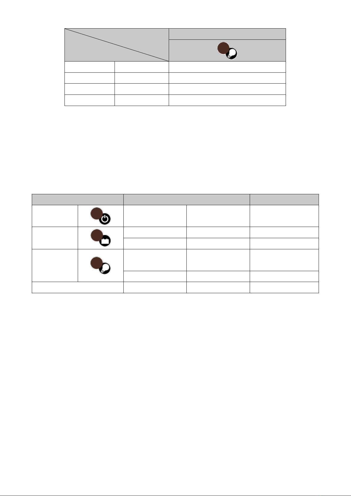
Table 6.4 The Indicators of protective functions
Lighting LED Indicators Protective Function
Power LED
Red
●
Overtemperature
Battery LED
Red
●
Input overvoltage
Blinking red
●●●●●
Input low voltage
Load LED
Red ●Overload/Load
terminal short-circuited
Blinking red
●●●●●
AC output error
All LEDs Red/ Blinking red
●/●●●●●
Internal error*
* Please consult with the dealer if an internal error occurs.

17
7. Troubleshooting Guide
Fault Condition
Possible Cause
Solution
No AC output
voltage
Input voltage error
Battery LED lights red/ blinks red
Check the value of DC input voltage
and adjust the range of input voltage.
Overtemperature protection
Power LED lights red
Check the status of the ventilation is
blocked or the air temperature is too
high. Please reduce the load capacity or
lower the outside air temperature.
Overload protection
Load LED lights red
Check the status of the load capacity,
including the instantaneous value,
exceeds the rated value of load or not.
Short-circuit protection
Load LED lights red
Check the status of the load wiring
connection is short-circuited or not.
AC output terminal wiring problem Check the status of the wiring to the AC
output terminal is appropriate or broken.
Internal error
All LEDs light red/blink red
It is possible that internal parts of the
Inverter may be damaged. Please
consult with the dealer.
Short operation
time of the
Inverter
Battery problem
Please change the battery.
Lack of battery capacity Please check the battery specifications
and increase the battery capacity.
Output voltage,
frequency error
Wrong setting Refer to Chapter 5-1 Change Settings,
and change the settings.
Power LED does
not light up even
connecting with
battery
Reversed connection of battery
polarity
Reverse connection warning LED
lights red
Correct the connection to the correct
polarity
The internal fuse cuts off Parts of the internal Inverter may be
damaged. Please consult with the
dealer.
Remote
connector does
not work
Wiring problem Check if the status of wire connection of
the remote connector is correct.
If the fault condition cannot be solved, please consult with the dealer.
DENRYO CO., LTD.
28
-5, Nishinippori 2Chome, Arakawa-ku
,
Tokyo 116
-0013, Japan
Phone :
+81-3-3802-3671
FAX : +81
-3-3802-2974
Email:
info-[email protected]
www.denryo.com/en
DM-5004
Table of contents
Popular Inverter manuals by other brands


BARRON
BARRON EXITRONIX Tucson Micro Series installation instructions

Baumer
Baumer HUBNER TDP 0,2 Series Mounting and operating instructions

electroil
electroil ITTPD11W-RS-BC Operation and Maintenance Handbook

Silicon Solar
Silicon Solar TPS555-1230 instruction manual

Mission Critical
Mission Critical Xantrex Freedom SW-RVC owner's guide

HP
HP 3312A Operating and service manual


