AP UC1200 User manual

1
USERS MANUAL
Feb. 12
Automatikprodukter

2
Feb. 12
Automatikprodukter

3
INDEX
1OVERVIEW............................................................................................................................................6
1.1 AVAILABLE MODELS........................................................................................................................6
1.2 IDENTIFICATION OF THE MACHINE...............................................................................................6
1.3 MARKING...........................................................................................................................................7
2PACKAGING AND TRANSPORT ........................................................................................................7
2.1 PACKAGING......................................................................................................................................7
3AVAILABLE VERSIONS.......................................................................................................................8
3.1 AVAILABLE ACCESSORIES.............................................................................................................8
3.2 POSSIBLE COMBINATIONS.............................................................................................................9
3.3 DIMENSIONS ..................................................................................................................................10
4ASSEMBLY OF THE MACHINE.........................................................................................................12
4.1 ASSEMBLY OF VERSION UC12 ....................................................................................................13
4.2 ASSEMBLY OF VERSION UC13 ....................................................................................................13
4.3 ASSEMBLY OF VERSION UC122 ..................................................................................................14
4.4 ASSEMBLY OF VERSION UC123 ..................................................................................................14
4.5 ASSEMBLY OF VERSION UC12S..................................................................................................15
4.6 ASSEMBLY OF VERSION UC13S..................................................................................................15
4.7 ASSEMBLY OF VERSION UC122S................................................................................................16
4.8 ASSEMBLY OF VERSION UC123S................................................................................................16
5INSTALLATION ..................................................................................................................................17
5.1 CORRECT POSITION OF CEILING-MOUNTED MACHINES........................................................17
5.2 INDICATIONS FOR CEILING..........................................................................................................19
5.3 FIXING IN CEILING .........................................................................................................................20
5.3.1 Installation type A......................................................................................................................21
5.3.2 Installation type B......................................................................................................................22
5.3.3 Number of supports to use .......................................................................................................23
5.4 ADDING A RE OXYGENISING UNIT ..............................................................................................23
5.5 PILOT UNIT AND SATTELITE UNIT ...............................................................................................24
5.6 ELECTRICAL CONNECTIONS .......................................................................................................24
5.6.1 Electrical connection.................................................................................................................24
5.6.2 Connection of re oxygenizing unit to a pilot unit .......................................................................25
5.7 ADDING A SATELLITE UNIT ..........................................................................................................26
5.7.1 Connection of high voltage cables............................................................................................26
5.7.2 Connecting cables for power and micro switch ........................................................................27
5.8 INSTALLED FILTERS......................................................................................................................28
5.8.1 Metallic prefilter.........................................................................................................................28
5.9 THE ELECTROSTATIC CELL .........................................................................................................28
5.9.1 Ionizing wires ............................................................................................................................29
5.9.2 Capitation blades ......................................................................................................................29
5.9.3 Insulators ..................................................................................................................................29
5.9.4 Printed circuit ............................................................................................................................29
6SAFETY FEATURES ..........................................................................................................................29
6.1 MECHANICAL SAFETY FEATUIRES .............................................................................................29
6.2 ELECTRICAL SAFETY FEATURES................................................................................................29
6.2.1 Safety features of electrical circuit ............................................................................................29
Feb. 12
Automatikprodukter

4
6.3 FUSES .............................................................................................................................................30
7ORDINARY MAINTENANCE..............................................................................................................31
7.1 FILTER MAINTENANCE..................................................................................................................31
7.1.1 Washing the filters ....................................................................................................................32
7.2 GENERAL INSPECTION OF THE FILTERS...................................................................................33
7.3 CLEANING THE MACHINE.............................................................................................................33
8EXTRAORDINARY MAINTENANCE..................................................................................................34
8.1 SOSTITUTION OF ION EMITTER NEEDLES.................................................................................34
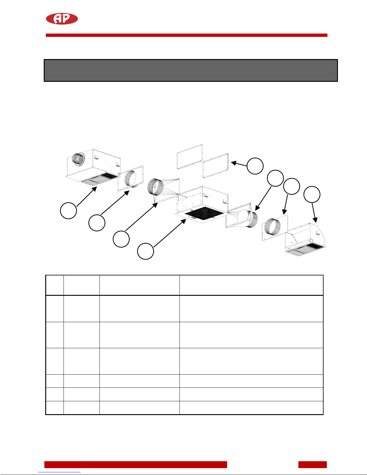
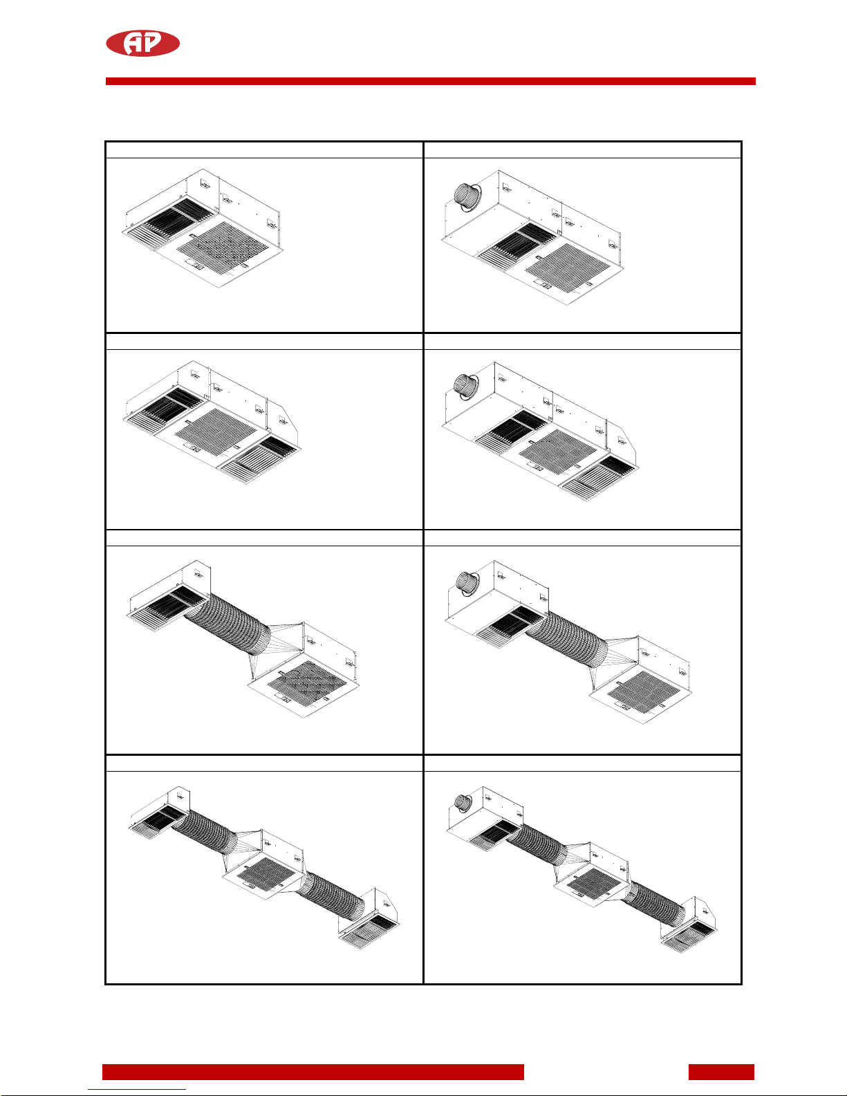
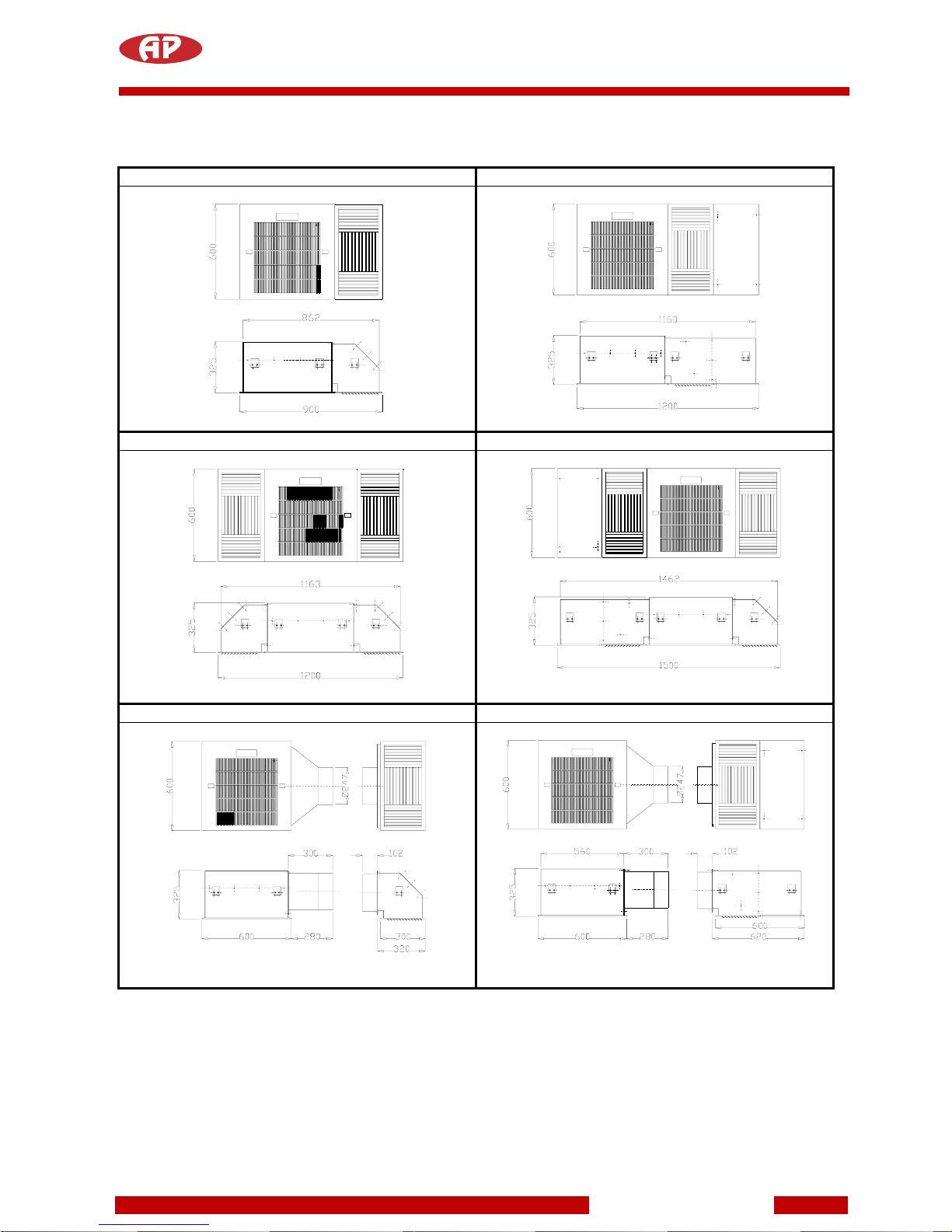
9AVAILABLE VERSIONS.....................................................................................................................35
10 NATURE SYSTEM ........................................................................................................................37
10.1 CONTROL PANEL .......................................................................................................................38
10.1.1 DISPLAY...................................................................................................................................38
10.1.2 RECEIVER................................................................................................................................38
10.1.3 MANUAL, TEST, ON-OFF FILTER AND RESET BUTTONS ..................................................39
10.1.4 OPERATION OF THE MACHINE.............................................................................................39
10.1.5 FILTERING STATUS ................................................................................................................40
10.2 INFRARED REMOTE CONTROL UNIT.......................................................................................40
10.3 POWER SUPPLY AND ANTI BLACK-OUT SYSTEM .................................................................40
10.4 ENVIRONMENTAL REVITALISATION (RIVITALIZZAZIONE AMBIENTALE®) ..........................41
10.5 PURIFICATION ............................................................................................................................41
10.6 NORMAL CONDITIONS OF OPERATION ..................................................................................41
10.7 NIGHT-TIME REVITALISATION WITH ENVIRONMENTAL DEODORIZATION ........................42
10.8 SIGNALS ......................................................................................................................................42
10.9 STATE OF FILTRATION EFFICIENCY .......................................................................................42
10.10 OPTIMAL APPLICATION OF THE REVITALIZER ......................................................................43
10.11 ELECTRONIC CIRCUIT ALARM SIGNALS ................................................................................44
10.12 ELECTRONIC CIRCUIT ANOMALOUS SIGNALS......................................................................45
11 AFC SYSTEM................................................................................................................................46
11.1 CONTROL PANEL .......................................................................................................................47
11.1.1 DISPLAY...................................................................................................................................47
11.1.2 (RECEIVER) .............................................................................................................................47
11.1.3 MANUAL, TEST, ON-OFF FILTER AND RESET BUTTONS ..................................................48
11.2 OPERATION OF THE MACHINE ................................................................................................48
11.3 FILTERING STATUS....................................................................................................................49
11.4 INFRARED REMOTE CONTROL UNIT.......................................................................................49
11.5 POWER SUPPLY AND ANTI BLACK-OUT SYSTEM .................................................................49
11.6 PURIFICATION ............................................................................................................................50
11.7 SIGNALS ......................................................................................................................................50
11.8 STATE OF FILTRATION EFFICIENCY .......................................................................................50
11.9 ELECTRONIC CIRCUIT ALARM SIGNALS ................................................................................51
11.10 ELECTRONIC CIRCUIT ANOMALOUS SIGNALS......................................................................52
12 BASIC SYSTEM ..............................................................................................................................53
12.1 CONTROL PANEL .......................................................................................................................54
12.2 VISUALISATION OF SPEED .......................................................................................................54
12.2.1 RECEIVER................................................................................................................................54
12.2.2 MANUAL AND ON-OFF FILTER BUTTONS............................................................................55
Feb. 12
Automatikprodukter

5
12.3 OPERATION OF THE MACHINE ................................................................................................55
12.4 INFRARED REMOTE CONTROL UNIT.......................................................................................56
12.5 POWER SUPPLY AND ANTI BLACK-OUT SYSTEM .................................................................56
12.6 PURIFICATION ............................................................................................................................56
12.7 SIGNALS ......................................................................................................................................56
12.8 STATUS OF FILTRATION EFFICIENCY.....................................................................................56
12.9 ELECTRONIC CIRCUIT ALARM SIGNALS ................................................................................56
13 TECHNICAL DATASHEETS...........................................................................................................58
14 CERTIFICATIONS ...........................................................................................................................58
14.1 CERTIFICATION C.N.R. ..............................................................................................................58
14.2 CERTIFICATION OF COMPONENTS .........................................................................................58
Feb. 12
Automatikprodukter

6
1 OVERVIEW
The air cleaner series UC1200 has been developed to improve the air quality in confined spaces. This
machine has been specifically developed for use with modular ceiling systems, and comes with three distinct
technology levels: Nature System, AFC System, Basic System.
1.1 AVAILABLE MODELS
The machine may be assembled in a number of configurations to optimise in the specific case.
Following combinations are available :
UC12
UC13
UC122
UC123
UC12s
UC13s
UC122s
UC123s
For all combinations, all technology levels may be applied Nature System, AFC System e Basic System.
1.2 IDENTIFICATION OF THE MACHINE
Tag
All machines are equipped with a tag showing model
and serial number. This tag is positioned inside the
machine (in order to access it, the inlet grill must be
removed.
Feb. 12
Automatikprodukter

7
The tag shows the technical characteristics and serial number of the machine.
Model
Type
Serial number
In case technical assistance is requested, always supply model, type and serial number of the machine, -as
can be read on the tag.
1.3 MARKING
The CE conformity mark is shown on the tag.
2 PACKAGING AND TRANSPORT
2.1 PACKAGING
The machine is supplied in a cardboard box internally lined with polystyrene.
We recommend keeping all the packaging just in case the machine has to be returned to the manufacturer
or the dealer for extraordinary maintenance or repairs.
The following objects should be found in the box:
the required machine
users' manual and guarantee leaflet
remote control unit
plug
TRANSPORT
To limit damage and consequent charges for unforeseen repair work, if the machine has to be sent to the
manufacturer for overhaul or repair, the following procedure is recommended:
- pack the machine in the original carton; if this is not possible, you must pack the machine with polystyrene
protection.
- ship to the manufacturer or to the local dealer.
-
Feb. 12
Automatikprodukter

8
3 AVAILABLE VERSIONS
Utilizing the available accessories the machine may be configured in eight distinct ways to provide maximum
results.
3.1 AVAILABLE ACCESSORIES
Num.
CODE
DESCRIPTION
USE
1 UC1200-00
UC1200-01
UC1200-31
UC1200-32
Filter unit available in three
technologies, additionally also
as satellite unit.
This component is present in all configurations
2 UC1200-B Air outlet unit The air outlet unit may be used singular, or in couples,
or combined with a re oxygenising unit. It may be
attaches to or remote from the filter unit
3 UC1200-R Re oxygenising unit For any possible combination one re oxygenising unit
may be used. It may be used alone or together with an
other air outlet unit, separate or attached to the filter
unit
4 UC1200-C Cone Ø250 Is applied to the filter unit when using separate air outlet
/ re oxygenising units
5 UC1200-P Connection panel with collar
Ø250
Applied to the outlet unit / re oxygenising unit in order to
connect the flexible ducting
6 UC1200-T Closing panel Is applied to the filter unit in cases where a single outlet
/ re oxygenising unit is used
3
5
4
1
6
4
5
2
Feb. 12
Automatikprodukter

9
POSSIBLE COMBINATIONS
UC12 UC13
UC1200 with single outlet unit
UC1200 with re oxygenising unit
UC122 UC123
UC1200 with two outlet units
UC1200 with both outlet unit and re oxygenising unit
UC12s UC13s
UC1200 with separate single outlet unit
UC1200 with separate re oxygenising unit
UC122s UC123s
UC1200 with two separate outlet units UC1200 with separate outlet and re oxygenising unit
PS: The flexible connection hose is ordered separately
Feb. 12
Automatikprodukter

10
3.2 DIMENSIONS
UC12 UC13
UC122 UC123
UC12s UC13s
Feb. 12
Automatikprodukter

11
UC122s
UC123s
Feb. 12
Automatikprodukter

12
4 ASSEMBLY OF THE MACHINE
As previously described, the machine may be supplied in eight configurations. The various components are
supplied separately in individual packings. It is necessary to assemble the components before proceeding
with the installation. The following tables may be found on the packings:
Packing 670x670
Packing 670x370
The different versions are supplied as follows:
Version
Packing
dimension
Type
Qty
Version
Packing
dimension
Type
Qty
670x670x400 A 1 670x670x400 A 1UC12
370x670x400 E 1
UC12s
670x670x400 D 1
670x670x400 A 1 670x670x400 A 1
670x670x400 B 1 670x670x400 B 1
UC13
670x400x30 G 1 370x670x400 F 1
670x670x400 A 1
UC13s
670x400x30 G 1UC122
670x670x400 C 1 670x670x400 A 1
670x670x400 A 1
UC122s
670x670x400 D 2
670x670x400 B 1 670x670x400 A 1
UC123
370x670x400 E 1 670x670x400 B 1
370x670x400 F 1
UC123s
670x670x400 D 1
Unità remota cod. UC1200-00
BASIC SYSTEM cod. UC1200-01
AFC SYSTEM cod. UC1200-31
UNITA’ FILTRANTE MODELLO
UC1200 A
NATURE SYSTEM cod. UC1200-32
UNITA’ DI RIOSSIGENAZIONE MODELLO
UC1200-R BUnità di riossigenazione cod. UC1200-R
Nr 2 Bocchette cod. UC1200-B
ACCESSORI PER UC1200
C
Nr 1 Bocchette cod. UC1200-B
Nr 1 Coni di raccordo Ø250 cod. UC1200-C
Nr 1 Pannello raccordo Ø250 cod. UC1200-P
D
Nr 1 Bocchetta cod. UC1200-B
ACCESSORI PER UC1200
E
Nr 1 Coni di raccordo Ø250 cod. UC1200-C
Nr 1 Pannello raccordo Ø250 cod. UC1200-P
F
Feb. 12
Automatikprodukter

13
4.1 ASSEMBLY OF VERSION UC12
a) Open the packings and extract the components
b) Remove the grill by pushing the black hatches towards the center
c) Extract prefilter and electrostatic cell
d) Position the outlet unit next to the filter unit (can be fixed to one side or the other)
e) Using the included self threading screws Ø3,8x9 secure the air outlet unit to the filter unit
f) Position the closure panel on the opposite side and secure using the same type of screws
g) To facilitate the fixing to the ceiling we recommend leave filter and grill out
4.2 ASSEMBLY OF VERSION UC13
a) Open the packings and extract the components
b) Remove the grill by pushing the black hatches towards the center
c) Extract prefilter and electrostatic cell
d) Position the re oxygenising unit next to the filter unit (to facilitate the installation we recommend to leave
all electrical connections on the same side)
e) Using the included self threading screws Ø3,8x9 secure to the filter unit
f) Position the closure panel on the opposite side and secure using the same type of screws
g) To facilitate the fixing to the ceiling we recommend leave filter and grill out
Electrical connections
Lower side Internal fixing
Lower side
Internal fixing
ATTENTION: the
outllet unit may be
secured externally
from three sides,
whereas the lower
side must be
secured from inside
the machine as
seen on the
drawing. The closing
panel however may
be secured to the
filter unit with four
external screws
ATTENTION: the re
oxygenising unit
may be secured
externally from three
sides, whereas the
lower side must be
secured from inside
the machine as
seen on the
drawing. The closing
panel however may
be secured to the
filter unit with four
external screws
Feb. 12
Automatikprodukter

14
4.3 ASSEMBLY OF VERSION UC122
a) Open the packings and extract the components
b) Remove the grill by pushing the black hatches towards the center
c) Extract prefilter and electrostatic cell
d) Position the outlet unit on the side of the filter unit
e) Using the included self threading screws Ø3,8x9 secure the air outlet unit to the filter unit
f) To facilitate the fixing to the ceiling we recommend leave filter and grill out
4.4 ASSEMBLY OF VERSION UC123
a) Open the packings and extract the components
b) Remove the grill by pushing the black hatches towards the center
c) Extract prefilter and electrostatic cell
d) Position the re oxygenising unit next to the filter unit (to facilitate the installation we recommend to leave
all electrical connections on the same side)
e) Using the included self threading screws Ø3,8x9 secure to the filter unit
f) Position the outlet unit on the opposite side and use the same screws securing to the filter unit
g) To facilitate the fixing to the ceiling we recommend leave filter and grill out
Electrical connections
Lower side
Lower side
Internal fixing
ATTENTION: the
outlet units may
be secured
externally from
three sides,
whereas the
lower side must
be secured from
inside the
machine as
seen on the
drawing
ATTENTION: the
re oxygenising unit
may be secured
externally from
three sides,
whereas the lower
side must be
secured from
inside the machine
as seen on the
drawing. This also
applies to the
outlet unit.
Internal fixing
Feb. 12
Automatikprodukter

15
4.5 ASSEMBLY OF VERSION UC12s
a) Open the packings and extract the components
b) Remove the grill by pushing the black hatches towards the center
c) Extract prefilter and electrostatic cell
d) Position the Ø250 cone to the side of the filter unit (can be secured on both right and left side)
e) Using the included self threading screws Ø3,8x9 secure the cone Ø250 to the filter unit
f) Position the closure panel on the opposite side and using the same screws secure it to the filter unit.
g) Position the Ø250 panel on the outlet unit and secure using the included screws Ø3,8x9
h) To facilitate the fixing to the ceiling we recommend leave filter and grill out
4.6 ASSEMBLY OF VERSION UC13s
a) Open the packings and extract the components
b) Remove the grill by pushing the black hatches towards the center
c) Extract prefilter and electrostatic cell
h) Position the Ø250 cone to the side of the filter unit (to facilitate the installation, we recommend to have
all electrical connections on the same side)
d) Using the included self threading screws Ø3,8x9 secure the cone Ø250 to the filter unit
e) Position the closure panel on the opposite side and using the same screws secure it to the filter unit
f) Position the Ø250 panel on the re oxygenising and secure using the included screws Ø3,8x9
g) To facilitate the fixing to the ceiling we recommend leave filter and grill out
Electrical connections
Feb. 12
Automatikprodukter

16
4.7 ASSEMBLY OF VERSION UC122s
a) Open the packings and extract the components
b) Remove the grill by pushing the black hatches towards the center
c) Extract prefilter and electrostatic cell
d) Position the Ø250 cones to the side of the filter unit
e) Using the included self threading screws Ø3,8x9 secure the cones Ø250 to the filter unit
f) Position the Ø250 panel on the outlet unit and secure using the included screws Ø3,8x9
g) To facilitate the fixing to the ceiling we recommend leave filter and grill out
4.8 ASSEMBLY OF VERSION UC123s
a) Open the packings and extract the components
b) Remove the grill by pushing the black hatches towards the center
c) Extract prefilter and electrostatic cell
d) Position the Ø250 cones to the side of the filter unit
e) Using the included self threading screws Ø3,8x9 secure the cones Ø250 to the filter unit
f) Position the Ø250 panel on the outlet unit and secure using the included screws Ø3,8x9
g) Repeat the operation for the second panel, this time on the re oxygenising unit.
h) To facilitate the fixing to the ceiling we recommend leave filter and grill out
Feb. 12
Automatikprodukter

17
5 INSTALLATION
The UC1200 is normally used in suspended ceiling systems. It is however also possible to install it with other
ceilings, - masking it in false beams etc.
5.1 CORRECT POSITION OF CEILING-MOUNTED MACHINES
CORRECT POSITION INCORRECT POSITION
Ceiling machines
must be installed at a
height from the
ground between 2.8
and 3.5 metres. If the
following indications
are respected during
installation, the
maximum efficiency
will be obtained.
The machine will
carry out its work by
pushing the air up
flush with the ceiling,
making it descend
down along the walls
and recalling it back
from the centre of the
room. The whole
room will be involved
in the cycle thanks to
the “coanda” effect.
Feb. 12
Automatikprodukter

18
The outlets are equipped with curved foils with air directions. The particular design of the foils permits an
optimal distribution pattern of the air, causing a so called "coanda" effect, also avoiding short circuiting in the
centre area. Do not replace these outlets with models from other manufacturers.
Outlet with curved foils used to optimize the air flow
Outlet with curved foils
Traditional outlet, -not recommended
Traditional outlet
Creating a shorting of the air stream in the middle, mixing with the air entering the machine
The UC outlet permits launching the air in
three directions, covering the whole
environment. When necessary, a group of
foils may be closed.
25%
12,5% 12,5%
12,5% 12,5%
25%
Feb. 12
Automatikprodukter

19
5.2 INDICATIONS FOR CEILING
The machine may be used with any type of ceiling. The dimensions are well suited for use in 600x600 ceiling
raster systems of T-profile type, such as most commonly found on the market.
The height of the machine requires at least 320mm space for proper installation.
Feb. 12
Automatikprodukter

20
5.3 FIXING IN CEILING
The machine may be directly fixed to the ceiling with appropriate fasteners for the type of ceiling material. It
is up to the individual installer to make sure that the fasteners are adequate for the intended use. The
machine is supplied with a hole template in order to avoid errors
.
The machine may be installed in two distinct ways :
a) through use of external suspension brackets
b) through holes in the ceiling side panel of the machine
TYPE A
Suspension with external bars. This method is always recommended for cases with easy access to the side
of the machine.
TYPE B
Suspension through the holes in the ceiling side panel. This is recommended when access to the side of the
machine is difficult.
Feb. 12
Automatikprodukter
Table of contents
Other AP Air Cleaner manuals