AP LifePro50p User manual

AIR QUALITY
MOBILE
50P Jan 2012
Automatikprodukter
USERS' MANUAL AND
INSTALLATION GUIDE

AIR QUALITY
MOBILE
50P Jan 2012
Automatikprodukter

AIR QUALITY
MOBILE
50P Jan 2012
Automatikprodukter
SUMMARY
1 GENERAL...................................................................................................................................................5
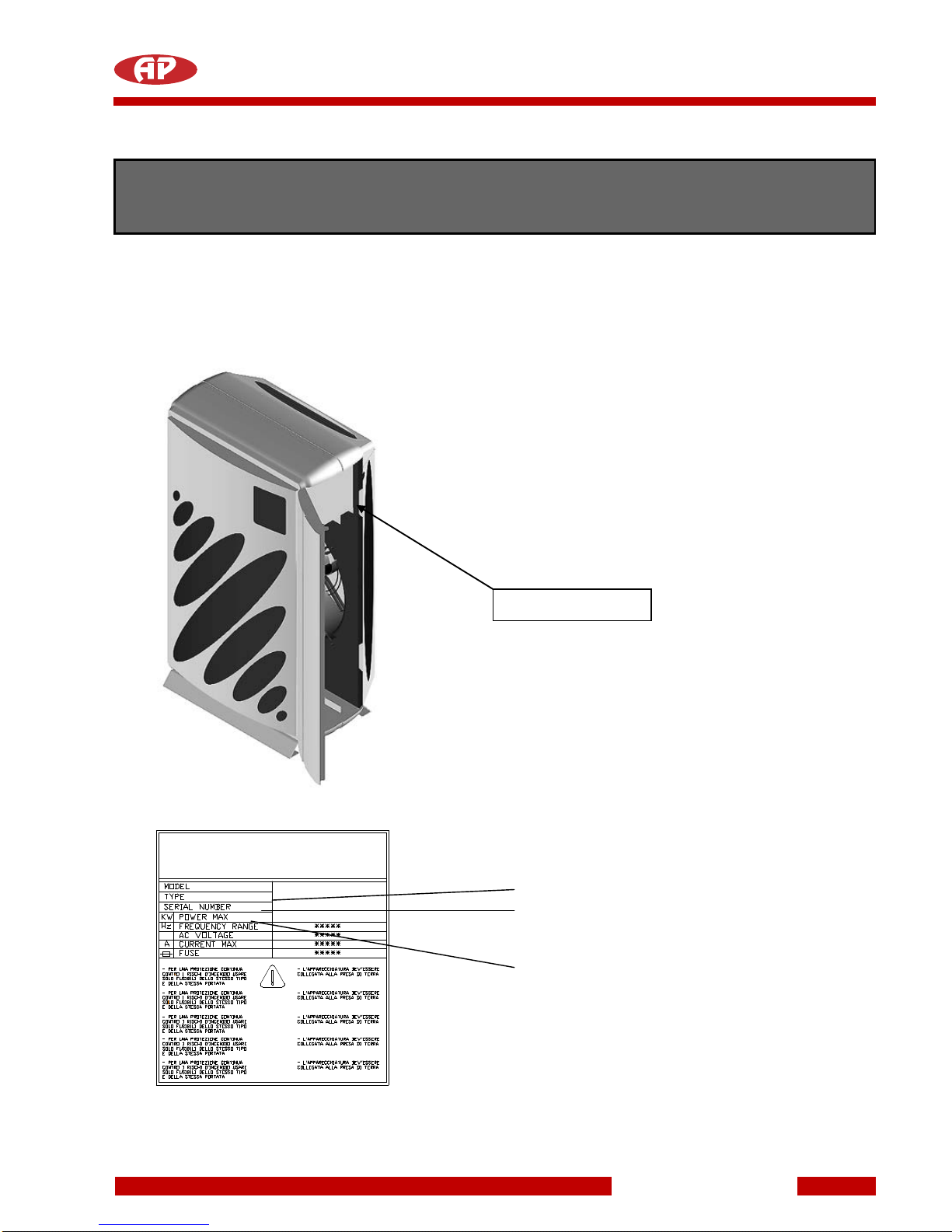
1.1 IDENTIFICATION OF THE MACHINE .................................................................................................5
1.2 MARKING OF THE MACHINE.............................................................................................................6
1.2.1 Opening the door ..........................................................................................................................6
2 PACKAGING AND TRANSPORT...............................................................................................................7
2.1 PACKAGING........................................................................................................................................7
2.2 TRANSPORT.......................................................................................................................................7
3 INSTALLATION OF THE MACHINE ..........................................................................................................8
3.1 VENTILATING THE PREMISES ..........................................................................................................9
3.2 FILTER UNIT........................................................................................................................................9
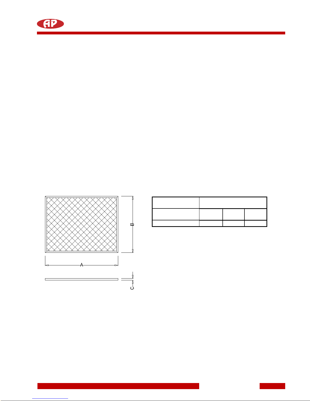
3.3 METAL PRE-FILTER............................................................................................................................9
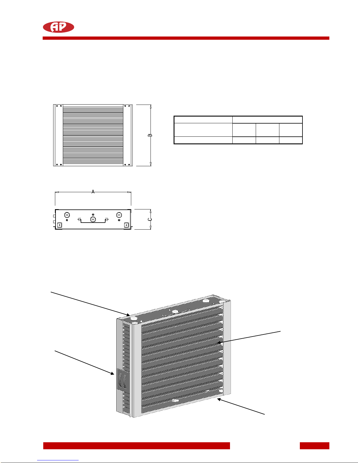
3.4 ELECTROSTATIC CELL....................................................................................................................10
3.4.1 ionisation wires............................................................................................................................11
3.4.2 collection blades..........................................................................................................................11
3.4.3 insulators.....................................................................................................................................11
3.4.4 contact terminal strip...................................................................................................................11
4 SAFETY DEVICES....................................................................................................................................11
4.1 MECHANICAL SAFETY DEVICES....................................................................................................11
4.2 ELECTRICAL SAFETY DEVICES......................................................................................................12
4.2.1 Electronic circuit protection devices............................................................................................12
4.3 FUSE ...................................................................................................................................................12
5 ORDINARY MAINTENANCE....................................................................................................................13
5.1 FILTER MAINTENANCE....................................................................................................................13
5.1.1 Access Door................................................................................................................................13
5.1.2 Washing the filters.......................................................................................................................14
5.2 GENERAL INSPECTION OF THE FILTERS......................................................................................15
5.3 CLEANING THE MACHINE................................................................................................................15
6 AVAILABLE VERSIONS...........................................................................................................................16
7 NATURE SYSTEM .................................................................................................................................18
7.1 CONTROL PANEL.............................................................................................................................19
7.1.1 DISPLAY.....................................................................................................................................19
7.1.2 RECEIVER..................................................................................................................................19
7.1.3 MANUAL, TEST, ON-OFF FILTER AND RESET BUTTONS.....................................................20
7.1.4 OPERATION OF THE MACHINE...............................................................................................20
7.1.5 FILTERING STATUS..................................................................................................................21
7.2 INFRARED REMOTE CONTROL UNIT.............................................................................................21
7.3 POWER SUPPLY AND ANTI BLACK-OUT SYSTEM........................................................................21
7.4 ENVIRONMENTAL REVITALISATION (RIVITALIZZAZIONE AMBIENTALE®).................................22
7.5 PURIFICATION..................................................................................................................................22
7.6 NORMAL CONDITIONS OF OPERATION ........................................................................................22
7.7 NIGHT-TIME REVITALISATION WITH ENVIRONMENTAL DEODORIZATION...............................23
7.8 SIGNALS............................................................................................................................................23
7.9 STATE OF FILTRATION EFFICIENCY..............................................................................................23
7.10 OPTIMAL APPLICATION OF THE REVITALIZER.............................................................................24
7.11 ELECTRONIC CIRCUIT ALARM SIGNALS.......................................................................................25
7.12 ELECTRONIC CIRCUIT ANOMALOUS SIGNALS ............................................................................26
8 AFC SYSTEM..........................................................................................................................................27
8.1 CONTROL PANEL.............................................................................................................................28
8.1.1 DISPLAY.....................................................................................................................................28
8.1.2 (RECEIVER) ...............................................................................................................................28

AIR QUALITY
MOBILE
50P Jan 2012
Automatikprodukter
8.1.3 MANUAL, TEST, ON-OFF FILTER AND RESET BUTTONS.....................................................29
8.2 OPERATION OF THE MACHINE.......................................................................................................29
8.3 FILTERING STATUS .........................................................................................................................30
8.4 INFRARED REMOTE CONTROL UNIT.............................................................................................30
8.5 POWER SUPPLY AND ANTI BLACK-OUT SYSTEM........................................................................30
8.6 PURIFICATION..................................................................................................................................31
8.7 SIGNALS............................................................................................................................................31
8.8 STATE OF FILTRATION EFFICIENCY..............................................................................................31
8.9 ELECTRONIC CIRCUIT ALARM SIGNALS.......................................................................................32
8.10 ELECTRONIC CIRCUIT ANOMALOUS SIGNALS ............................................................................33
9 BASIC SYSTEM........................................................................................................................................34
9.1 CONTROL PANEL.............................................................................................................................35
9.2 VISUALISATION OF SPEED .............................................................................................................35
9.2.1 RECEIVER..................................................................................................................................35
9.2.2 MANUAL AND ON-OFF FILTER BUTTONS..............................................................................36
9.3 OPERATION OF THE MACHINE.......................................................................................................36
9.4 INFRARED REMOTE CONTROL UNIT.............................................................................................36
9.5 POWER SUPPLY AND ANTI BLACK-OUT SYSTEM........................................................................36
9.6 PURIFICATION..................................................................................................................................37
9.7 SIGNALS............................................................................................................................................37
9.8 STATUS OF FILTRATION EFFICIENCY...........................................................................................37
9.9 ELECTRONIC CIRCUIT ALARM SIGNALS.......................................................................................37
10 TECHNICAL DATA ...............................................................................................................................38
11 CERTIFICATIONS.................................................................................................................................38
11.1 CERTIFICATION C.N.R.....................................................................................................................38
11.2 CERTIFICATION OF COMPONENTS...............................................................................................38

AIR QUALITY
MOBILE
50P Jan 2012
Automatikprodukter
1 GENERAL
Air cleaners and Revitalizers 50P, built for the purposes of improving the characteristics of the air in closed
environments.
There are available two different technologies: Nature System, Basic System.
1.1 IDENTIFICATION OF THE MACHINE
identification plate
There is a plate in every machine showing the
model and the series number which identify the
machine.
This plate is located on the inside of the machine
and it is therefore necessary to open the door of
the machine itself to see it.
The plate shows the technical
data of operation and the sign of
identification of the machine.
When you call for technical
assistance, provide the data
relative to the model of the
machine, its type and series
number.
Model
Type
N series number

AIR QUALITY
MOBILE
50P Jan 2012
Automatikprodukter
1.2 MARKING OF THE MACHINE
The EC conformity mark is located on the control panel of the machine.
1.2.1 Opening the door
For opening the door it is necessary to introduce a finger in the proper slit and pull.
slit for opening the door

AIR QUALITY
MOBILE
50P Jan 2012
Automatikprodukter
2 PACKAGING AND TRANSPORT
2.1 PACKAGING
The machine is supplied in a cardboard box internally lined with polystyrene.
We recommend keeping all the packaging just in case the machine has to be returned to the manufacturer or
the dealer for extraordinary maintenance or repairs.
The following objects should be found in the box:
-the required machine
-users' manual and guarantee leaflet
-remote control unit
- plug
2.2 TRANSPORT
To limit damage and consequent charges for unforeseen repair work, if the machine has to be sent to the
manufacturer for overhaul or repair, the following procedure is recommended:
-pack the machine in the original carton; if this is not possible, you must pack the machine with polystyrene
protection.
-ship to the manufacturer or to the local dealer.

AIR QUALITY
MOBILE
50P Jan 2012
Automatikprodukter
3 INSTALLATION OF THE
MACHINE
For a correct function, place the machine so that the air can fulfil the cycle as figured on the picture. The air
that comes out of the hinder air diffuser must not find near obstacles which can obstruct to close the cycle of
purifying.

AIR QUALITY
MOBILE
50P Jan 2012
Automatikprodukter
3.1 VENTILATING THE PREMISES
All rooms where people are present carrying out any activity must be fitted with appropriate apparatuses
which guarantee adequate reoxygenation of the environment.
This reoxygenation is fundamental for the well-being of people and must be realised bearing in mind that
every person needs at least 12.5m3of air every hour where there is a high-efficiency air purification system.
It is therefore necessary to provide the premises with an air introduction system in proportion to the average
number of people present in them.
To calculate the quantity of air in m3/h to introduce from the exterior, it is sufficient to multiply the average
number of persons present by a coefficient of 12.5.
3.2 FILTER UNIT
There are two different filters in the machine:
-metal pre-filter 50P
-electrostatic cell 50P
3.3 METAL PRE-FILTER
The metal pre-filter is for trapping the bigger particles present in the air and for distributing the flow uniformly.
Depending on the model it is fitted in, it can have different dimensions which are illustrated below.
DIMENSIONS
FILTER MODEL
A
B
C
50p
344
310
6
During operation, the metal pre-filter must always be inserted in its seat.
During maintenance, it must be handled with care to prevent deformation or damage

AIR QUALITY
MOBILE
50P Jan 2012
Automatikprodukter
3.4 ELECTROSTATIC CELL
The electrostatic cell filters the pollutant particles with an efficiency of 99%.
Its dimensions vary depending on the model it is fitted in.
DIMENSIONS
FILTER MODEL
A
B
C
50p
344
310
115
The cell is built entirely in anticorodal aluminium. There are four distinct zones in the cell:
A - ionisation wires
B - collection blades
C - insulators
D - contact terminal strip
C
A
D
B

AIR QUALITY
MOBILE
50P Jan 2012
Automatikprodukter
3.4.1 ionisation wires
The electrostatic cell has 9 ionising wires. These must be intact, clean and well-tensioned at all times. If one
breaks, it is necessary to replace it. The technical service must be called in this case.
The manufacturer will not guarantee the efficiency of the filter unit if non-original wires are inserted or wires
which are not of the type recommended by the technical service.
3.4.2 collection blades
The function of the collection blades which make up the central body of the cell is to capture and hold the
pollutant agents. Visually, the blades must be straight, without undulations and free from trapped foreign
bodies.
3.4.3 insulators
The insulators are built in an extremely high quality ceramic material and their function is to electrically
insulate the high-voltage parts of the electrostatic cell from the earthed parts.
They must be dry and thoroughly clean after maintenance.
3.4.4 contact terminal strip
The terminal strip for the contacts is the point through which the electrical connection is made between the
electronic circuit and the electrostatic cell. During maintenance, inspect to ensure that the flexible arches are
intact. Also ensure that there are no burns or cracks on the terminal strip caused by the voltage.
4 SAFETY DEVICES
The machine is fitted with mechanical and electrical safety devices which must not be removed or altered for
any reason.
4.1 MECHANICAL SAFETY DEVICES
The grill, where the air to be cleaned passes through, is designed to protect persons from accidental contact
with the live parts. This grill can only be removed in the event of extraordinary maintenance or repair
operations.
In all cases, before removing it, it is necessary to cut off the electrical power.
NEVER INSTALL OR START THE AIR PURIFIER WITHOUT THE PROTECTIVE GRILL.
There are air diffusion fins in the top of the machine. They have the double function of diffusing the purified
air and avoiding accidental contact with the electric fan which, in turn, is protected inside by a further
protective grill. These fins can only be removed in the event of extraordinary maintenance or repair
operations. In all cases, before removing a safety device, it is necessary to cut off the electrical power.
NEVER INSTALL OR START THE MACHINE WITHOUT THE DIFFUSION FINS.

AIR QUALITY
MOBILE
50P Jan 2012
Automatikprodukter
4.2 ELECTRICAL SAFETY DEVICES
The machine is provided with a door, through which access to the filters is permitted so as to carry out
normal maintenance. This door is provided with a pin which actuates a safety switch, which cuts off the power
supply if the door is opened without first cutting off the power by disconnecting the plug.
The pin which actuates the microswitch must not be modified for any reason, and must not be blocked in the
closed position in any way so as not to compromise safety. If the microswitch is broken the machine will stop.
Contact the technical service for the replacement of this component.
CUT OFF THE POWER SUPPLY BEFORE CARRYING OUT ANY OPERATION ON THE MACHINE.
4.2.1 Electronic circuit protection devices
The electronic circuit is provided with a series of protection devices which automatically cut off the high
voltage whenever a machine malfunction occurs which could lead to its breakdown. There is a thermal fuse
inside the machine (available only for the versions AFC System and NATURE System) which cuts off the
power supply if a short circuit occurs in the electronic section down-line from the transformer.
There is a mains protection fuse in the power plug which cuts off the power to the machine in the event of
short-circuiting of the transformer.
4.3 Fuse
Inside the machine is inserted a fuse, which you can find as follows:
-cut off the power supply of the machine
-open the door
-remove the cell and pre-filter
-open the fuse holder
Blown fuses must be replaced with others with the same characteristics and has to be done by the technical
service.
Fuse holder

AIR QUALITY
MOBILE
50P Jan 2012
Automatikprodukter
5 ORDINARY MAINTENANCE
Ordinary maintenance involves:
-maintenance of the filter unit
-general inspection of the machine
Extraordinary maintenance is carried out by specialised personnel.
5.1 FILTER MAINTENANCE
To carry out filter maintenance, it is necessary to gain access to them through the provided door and
consists in washing the filter cell and the metal pre-filter
5.1.1 Access Door
For opening the machine, pull the door on the upper part.

AIR QUALITY
MOBILE
50P Jan 2012
Automatikprodukter
5.1.2 Washing the filters
Filter maintenance is important both for the correct operation of the machine and for constant performance
with the passage of time. The following materials are required for maintenance:
1) Two plastic trays, one with the bottom raised 2-3 cm for decanting the dirt. As an alternative to the raised
bottom, use a stainless steel frame.
2) Non-corrosive detergent for washing the electrostatic cells, supplied by an authorised dealer.
3) A rubber tube for rinsing the filters.
4) Vinegar.
Prepare the tray with the raised bottom with warm water (max 45°C). Dilute the detergent in the proportions
indicated on the label of the detergent itself.
Put the vinegar and water in the other (1 litre of vinegar for every 20 litres of water).
warm water and detergent
tray in plastic or stainless steel
electrostatic cell
frame in stainless steel
To wash, proceed as follows:
a) immerse the electrostatic cell in the tray with the detergent and soak until the dirt is dissolved
b) remove the electrostatic cell and rinse thoroughly with running water, taking care not to break the
ionisation wires
c) immerse the cell in the tray containing the water and vinegar and leave to soak for 5-10 minutes.
rinsing with current water drying

AIR QUALITY
MOBILE
50P Jan 2012
Automatikprodukter
d) remove the cell and leave it to dry in a warm place, keeping it raised from the ground by wooden strips
(ovens with a maximum temperature of 60°C are tolerated).
e) examine the state of the ionisation wires, stretching them slightly to check their mechanical strength. Use
a cotton flock and methylated spirits to remove any residual traces of dirt.
f) Ensure that the cell is thoroughly clean and dry before reinstalling it.
When maintaining the pre-filter, first remove the dust deposited in it using an ordinary vacuum cleaner. Then
proceed with washing as follows:
a) Immerse the pre-filter in the tray containing the detergent diluted in warm water and leave to soak for
about half an hour.
b) Remove the pre-filter from the tray and rinse thoroughly with water.
c) Leave to dry in a warm ventilated environment.
5.2 GENERAL INSPECTION OF THE FILTERS
The state of the filters must be inspected every time they are washed so as to prevent air cleaner malfunction
and problems.
INSPECTION
FAULT
OPERATION
ionisation wires
breakage of a wire
change the ionisation wire
ionisation wires
rough surface with material
deposits
clean the wire with a cloth soaked
in alcohol or replace
ceramic insulators
dirty with material deposits
wash the cell again
ceramic insulators
breakage or presence of cracks
replace the insulators
high voltage terminal strip
burning caused by high voltage
replace the high voltage terminal
strip
The following inspections must be made on the filters:
-check that the internal mesh of the pre-filter is compact and that no wires protrude from the containing
meshes.
- check that the frame is not deformed or damaged.
If the pre-filter is badly damaged, replace it with a new one.
5.3 CLEANING THE MACHINE
To clean the outside, use a cloth sprayed with methylated spirits.
Use a brush with soft bristles to clean the air outlet fins.
To clean the inlet grill, use a vacuum cleaner with a dusting attachment.

AIR QUALITY
MOBILE
50P Jan 2012
Automatikprodukter
6 AVAILABLE VERSIONS
The 50P line is manufactured in tree versions. For distinguishing which version you have, you should control
the label placed outside on the machine or to check the control panel.
Nature System®is the Top version and identifies the Environmental Revitalizer. It is used a digital technology
for the controlling of all functions. The operations carried out by this machine are reported in the following
definitions.
NATURE SYSTEM ®
Identifies the method used in confined environments to obtain an air quality as close as possible to a “natural”
one.
ENVIRONMENTAL REVITALISATION (RIVITALIZZAZIONE AMBIENTALE®)
Identifies the operation carried out by the apparatus to create ionic equilibrium, inside a confined
environment, as close as possible to the ideal one for well-being.
ENVIRONMENTAL REVITALIZER (RIVITALIZZATORE AMBIENTALE®)
Identifies the apparatus which, in an equilibrated manner, carries out various complex operations with the
maximum security and reliability to render the environment comfortable, with characteristics similar to natural
ones uncontaminated by the presence of man.
HIGH-EFFICIENCY FILTERING
Identifies the operation of purifying the confined environment. This operation is carried out with an efficiency
which is constant with time and in a completely autonomous manner, thanks to the microprocessor which
guarantees optimal performance whatever situations it is used in.
NIGHT-TIME DEODORIZATION
Identifies the work carried out by the Revitalizer during the night to eliminate the stagnant odour from the
premises as well as typical residual odours in badly-aired environments.
The air is fresher and bracing the next day.

AIR QUALITY
MOBILE
50P Jan 2012
Automatikprodukter
AFC SYSTEM®is the Top version of Environmental Air Purifiers and is using a digital technology for the
controlling of its functions. The operations carried out by this machine are reported in the following definitions:
AFC SYSTEM®
Identifies the method used by the microprocessor of the machine to gesture in complete autonomously way
the parameters of the filtration, depending from the chosen performance of function and the level of
saturation of the electrostatic cell.
HIGH-EFFICIENCY FILTERING
Identifies the operation of purifying the confined environment. This operation is carried out with an efficiency
which is constant with time and in a completely autonomous manner, thanks to the microprocessor which
guarantees optimal performance whatever situations it is used in.
BASIC SYSTEM is a basic version and is using a traditional technology.

AIR QUALITY
MOBILE
50P Jan 2012
Automatikprodukter
7 NATURE SYSTEM
The NATURE SYSTEM® is composed of the following elements:
Electronic control of environmental revitalisation (rivitalizzazione ambientale®)
The System automatically carries out all the controls and gives the commands to the Environmental
Revitalisation along with the information required on the operating status of the apparatus.
Infrared remote control unit
The remote control unit allows the user to control the operation of the Revitalizer from a distance of about
6÷7 metres; in particular, the air flow can be varied.
High-efficiency filtration unit
This element feeds the filtering System in a completely automatic manner, maintaining constant high
efficiency in all situations.
Environmental Revitalisation Unit
This element feeds environmental revitalisation in an optimal manner to reach ionic equilibrium in completely
different situations and environments.

AIR QUALITY
MOBILE
50P Jan 2012
Automatikprodukter
7.1 CONTROL PANEL
All information regarding the operating status of the machine is displayed on the control panel.
The control panel allows the user to:
- select the air flow
- activate/deactivate environmental revitalisation
- turn off any alarms indicating apparatus malfunctions
- constantly control all the functions relating to operation (air flow, environmental revitalisation,
filtration efficiency, alarm situation).
The devices which permit manual operation and visual control of the operating conditions are given here
below.
7.1.1 DISPLAY
When the machine works normally, the single-figure display shows the operating air flow (0-1-2-3).
If, on the other hand, the letter F appears, this means that operation of the electrostatic cell is not correct.
The reason may be a deposit of pollutant on the surface of the ionisation wires (see paragraph
"ELECTRONIC CIRCUIT ALARM SIGNALS").
If the letter F appears together with the indication ALARM, the operation of the Revitaliser does not
stop, however it is an indication of efficiency reduction.
7.1.2 RECEIVER
The receiver permits the reception of the signal coming from the infrared remote
control unit to obtain speed changes, activation of the night-time deodorization
phase or switching off of the apparatus; if one of the four remote control buttons
has been pressed, the Led flashes for about 1 second.
The control panel is divided in three zones:
1 – COMMANDS AND VISUALISATION OF
THE SPEED
2 – FILTERING STATUS
3 – OPERATION OF THE APPARATUS

AIR QUALITY
MOBILE
50P Jan 2012
Automatikprodukter
7.1.3 MANUAL, TEST, ON-OFF FILTER AND RESET
BUTTONS
The MANUAL button allows the air flow to be modified manually (0-1-2-3);
the setting is memorised and maintained even if there is a power failure.
The machine can be turned off by turning to flow 0 (fan off).
Pressing the button indicated, a test on the operation of the electronic circuit
signals is carried out. The air purifier is in perfect operating conditions only if
all the Leds go on. Otherwise call our service network.
The ON/OFF button is for activating/deactivating the filtration or revitalisation
function. It is used when you need to completely dry the filtering unit after
washing, or to use the machine for the ventilation function only.
The RESET button is for turning off the ALARM signal if the circuit protection
device has tripped as a result of a continuous discharge or short circuit in the
electrostatic cells. If the alarm persists even after resetting, call the technical
service.
7.1.4 OPERATION OF THE MACHINE
These four LEDs indicate the operating status of the environmental
Revitalizer:
- MAINS
(green Led):
power on (constant)
- ALARM
(red Led):
- FILTER ON
(yellow Led):
- ION- ON
(yellow Led):
when this is on, it means that there is a problem
with the high-efficiency filtration unit.
All the filtration and revitalisation functions are
stopped (call the technical service).
when this is on, it means that filtering is on.
when this is on, it means that revitalisation is on
(ionic re-equilibrium).
Table of contents
Other AP Air Cleaner manuals