Apach AP5M GAS User manual

USE AND
MAINTENANCE
MANUAL
AP5M GAS - AB4M GAS
AP7M GAS - AB6M GAS
AP10M GAS - AB10M GAS
Rev. 2013-06.05

2
Index
1. Installation
1.1 General and safety warnings 3
1.2
Connection to gas supply
4
1.3
Checking gas pressure
6
1.4
Replacing nozzles (gas type change)
6
1.5 Electric connection 7
1.6
Fume discharge
8
1.7
Connection to the drain
8
1.8 Switching on oven and testing 9
2. Use instruction
2.1 Preliminary information 10
2.2 Control Panel 11
2.3 Convection cooking 12
2.4 Steaming 13
2.5 Convection/steam combi cooking 14
2.6 Humidity draining valve 15
2.7 Compartment lighting 15
2.8 Stop and oven swich off 15
2.9 Flame control (gas ovens only) 15
2.10 Other versions 16
4. What to do if...
4.1 Most common problems 18
4.2 Safety thermostat of the cooking
compartment
19
3. Maintenance
3.1 Cleaning 17
3.2 Cleaning of the glass 17
Dear Customer,
We thank you for having purchased our product.
This oven is part of a line of appliances specically designed for baking and patisserie, made of gas and electric
ovens with different capacities. The pleasant and modern design of these ovens provides ease of use, ergonomics
and cooking control.
The oven has a 12 month warranty against any manufacturing faults, starting from the date on the sales invoice.
The warranty covers the normal functioning of the oven and does not include the consumption materials (lights,
gaskets, etc.) and faults caused by incorrect installation, wear, maintenance, repair, decalcication & cleaning,
tampering and improper use.
The manufacturer reserves the right at any time to make changes or necessary amendments to the product.
5. Data sheet
5.1 AP5M GAS - AB4M GAS
MME523
20
5.2 AP7M GAS - AB6M GAS 20
5.3 AP10M GAS- AB10M GAS 21
6. Electrical drawings
Electrical drawings 22-24

3
Use and maintenance manual
• Carefully read this manual before installing and com-
missioning the oven. The text gives important indi-
cations regarding the safe installation, operating and
maintenance of the equipment.
• Keep this manual in a safe and easily accessible place
for further consultation by the operators.
• In case of transferring the oven, always attach the ma-
nual; if necessary, a new copy must be requested from
the authorised dealer or directly from the manufactu-
ring company.
• Once unpacked, ensure the oven is intact and does not
show signs of damage due to transport. A damaged
appliance must never be installed and commissioned; if
in doubt, immediately contact the after-sales technical
assistance or your own dealer.
• The appliance has been designed to cook food in closed
premises and must only be used for this purpose: any
other use must, therefore, be avoided as considered
improper and dangerous.
• The device is intended for professional use only by qua-
lied personnel
• The oven must only be used by staff adequately trained
for its use. To avoid the risk of accidents or damages to
the appliance, it is also fundamental that staff regularly
receive precise instructions regarding safety.
• The oven must not be used by persons with reduced
physical, sensorial or mental capacities or by persons
without experience and knowledge, unless supervised
or educated regarding the operating of the appliance by
a person responsible for their safety.
• Installation, extraordinary maintenance and repair
operations on the equipment must only be carried out
by professionally qualied staff.
• Children must be supervised to assure they do not
play with the appliance or use it.
• Caution! During working conditions, the external sur-
faces of the equipment may exceed 60 C.
• In case of fault or bad functioning, the equipment
must be deactivated; in case of repair, contact only
an after-sales technical assistance centre authorised
by the manufacturer and request original spare parts.
• Do not position other heat sources like, fryers or
hotplates, near the oven.
• Do not deposit or use ammable substances near the
equipment.
• In case of prolonged disuse of the appliance, both the
water and electric energy supply must be shut-off.
• Before commissioning the equipment, ensure to have
removed all packaging, being careful to dispose of it in
compliance with the Standard in force.
• Amendments to the oven wiring are not admitted.
• The non-compliance with the above warnings can je-
opardise the safety of the equipment and may injury
the operator of the oven.
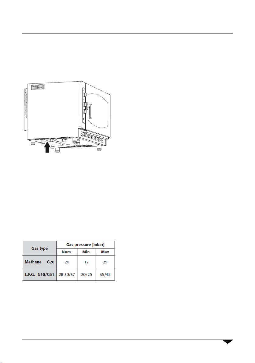
The gas ovens comply with the essential requirements of 90/396/EEC Gas Directive and therefore have the EC
conformity certicate issued by an approved body. They satisfy the requirements of the following gas regulations:
• EN 203 + subsequent amendments;
• EN 437 + subsequent amendments.
Installation must be carried out in compliance with safety requirements contained in the following regulations:
• UNI CIG n° 7222-7723-8723 + subsequent amendments.
The appliance complies with the essential requirements of the Low Voltage Directives 2006/95/CEE. It satises the
requirements of the following electrical regulations:
• EN 60335-1 + subsequent amendments;
• EN 60335-2-42 + subsequent amendments;
• EN 60335-2-46 + subsequent amendments;
• EN 60335-2-36 + subsequent amendments;
• EN 55104 / EN 55014 + subsequent amendments;
• EN 61000 + subsequent amendments.
The appliance complies with the essential requirements of the Electromagnetic Compatibility Directive 2004/108/
CEE.
1. Installation
1.1 General and safety warnings

4
1. Installation
1.2 Connection to gas supply (for gas ovens only)
The oven is factory set for the type of gas spe-
cied in the order.
The label attached to the appliance indicates
which type of gas the oven has been set for.
During testing, the gas produced throu-
gh combustion (CO2 and CO) should be
analysed and the nominal heat rating
should be measured to ensure that the
burners have been correctly calibrated
for the type of installation required.
Data collected should be written down and in-
cluded in the technical documentation of the
appliance.
Installation instructions
The oven should be installed and commissioned by qualied technicians in compliance
with current regulations and legislation.
Gas appliances, electrical connections and rooms where the appliance is to be sited
must comply with current regulations and legislation.
The air requirement of the burners is 2 m3/h per kW of power installed.
Premises open to the public must comply with accident prevention laws and re safety
regulations. A exible metal hose can be used to connect the appliance to the gas sup-
ply; make sure you t an approved tap in a point that is easy to reach.
Make sure that the exible hose is not twisted or over-stretched or in contact with parts
of the oven subject to overheating.
Use locking clamps complying with installation regulations.
Checks to be carried out prior to installation.
Check the label on the left-hand panel of the oven to make sure that the appliance has
been set for the type of gas on your premises.
Check the label to make sure that the capacity of the gas pressure reducer is adequate
for the supply of the appliance.
Do not insert section reducers between the reducer and the appliance.
We recommend tting a gas lter between the tap and pressure regulator to ensure
perfect performance.

5
Use and maintenance manual
Connect the oven to the gas supply using a special R 1/2”
hose with an internal section of at least 16 mm.
Connection to gas supply must be carried out using rigid or
exible metal pipes. Use taps or gates with an internal diame-
ter that is greater than that of the hose.
After connecting the appliance to the gas supply make sure
that there are no leaks from joints or connections. You can
test for leaks by using soapy water or foaming agent for leak
detection.
Gas ovens should be inspected in compliance with spe-
cic regulations once a year by an authorised techni-
cian who will analyse combusted gases and check no-
minal heat rating.
The appliance can work correctly only when gas pres-
sure keeps within specic values for each gas type (see
table).
If the pressure falls outside these values, it will not be possible
to achieve optimum functioning of the appliance and for it to
be installed correctly. Should this happen, call a technician to
check your gas mains (ducts, gates and eventually pressure
reducers) then, if necessary, contact your gas provider.
1. Installation

6
666666666666
1. Installation
1.3
Control of Gas Pressure (for gas ovens only)
Check that the installed nozzles are correct for the type and pressure of supplied gas. If you need to change the
nozzles, read the following paragraph.
1.4
Replacing nozzles (gas type change) (for gas ovens only)
Category of appliance: II2H3+ Country: IT- ES -PT- CH-GB -GR - IE
Oven Nominal
Power
Nozzle for
G30 gas [30 mbar]
Nozzle for
G31 gas [37 mbar]
Nozzle for
G20 gas [20 mbar]
5 GN 1/1 9,5 kW 115 110 161R
7 GN 1/1 16 kW 145 135 195R
10 GN 1/1 19 kW 155 145 225R
Use only original nozzles which must not be tampe-
red with them in any way!
For connection to a type of gas that is different from the
one specied on the rating plate, the burner/s and nozzle/s
must be replaced as follows:
• Unscrew nozzle to be replaced and replace it with the
one that corresponds to the type of gas to be used.
• Ret washer.
• Nozzles are marked in hundredths of a millimetre.
• After replacing the nozzle/s, check gas pressure.
When the appliance is connected, turn it on and check the
gas pressure.
Check gas pressure directly on the valve, as described
below:
• Unscrew screw “P” on the pressure outlet of the valve.
• Apply the pressure gauge to the pressure outlet.
• Regulate gas pressure to the values of table 2 by adju-
sting the pressure reducer outside the oven
• When the pressure is at the correct level, switch off
the oven, remove the pressure gauge and replace
screw “P”.
If the adjustment of the pressure is not sufcient, act as
follows:
• Remove the protective cap A.
• Screw to increase the pressure of the outlet gas acting
on the screw Band unscrew to decrease.
• At the end of the calibration reapply the protective
cap A.
A
P
B

7
Use and maintenance manual
1. Installation
1.5
Electric connection
The electric system, as prescribed and specied by the Standard in force, must be
equipped with an efcient ground. It is possible to guarantee the electric safety of the
appliance only in the presence of Standard electric system.
For direct connection to the mains, it is necessary to interpose a device between the
equipment and the same mains, sized for the load, that ensure its disconnection. The
contacts must have an opening distance enabling the full disconnection, in conditions
of over-voltage category III, per compliance with installation regulations.
This device also must be located in a place and in a manner to be easily accessible at
any moment by the operator.
Bring the main switch, to which the power supply cable plug will be collected, in position
0 (zero).
Have professionally qualied staff check that the plug cables section is adequate to the
power used by the appliance.
Loosen the screws xing the left side of the oven and extract it.
Connect the cable to the terminal board
following the indications on “tab 1”.
Lock the cable with the cable presser.
The power supply voltage with machine
functioning,must not be different from the
nominal voltage value by ±10%.
The equipment must be included in an equipotential system which efciency must be
checked according to that reported in the Standard.
For the connection there is a clamp, located on the frame and marked with the symbol
to which a cable with minimum section of 10 mm² must be connected.
For gas ovens, complete gas connection to the appliance before assembling the
oven side again;
for electric ovens assemble the oven side.
ELECTRIC OVENS GAS OVENS
L1 L2 L3 N N L N X
tab 1
Between phases
and there must be
a potential difference
of 230 V

8
1. Installation
1.6
Fume discharge (for gas ovens only)
Ovens should only be installed in adequately ventilated rooms in compliance with installation regulations.
The oven discharge can be connected by means of a forced evacuation system (e.g. hood tted with an extractor
fan). In this case the gas supply to the appliance must be controlled by the extraction system and will be interrupted
if the extraction capacity drops below the prescribed values. When installing the appliance beneath a hood take
care to ensure that:
a) the extracted volume is greater than the volume of com-
busted gas produced (refer to current regulations);
b) the hood lter is made from a heat-resistant material
(combusted gases may reach 300°C;
c) the nal section of the gas discharge tube must be inser-
ted inside the hood;
d) following interruption of gas supply the gas will be
switched on manually.
1.7
Connection to the drain
The oven must be connected to an open drain (funnel).
There is a sleeve (A) present in the lower part of the cooking
chamber (in the centre)to which the bendand and the rigid pipe
supplied (p) must be connected. Couple the bend in the rigid pipe
and connect it to the oven. Now, take the rigid pipe into the funnel
(not provided).
Another exible hose is present, which connects the front basin.
This hose must also be made to ow into the funnel.
A
B
p

9
Use and maintenance manual
1. Installation
1.8 Switching on oven and testing
Before switching on the oven, carefully check that all systems and installation of the appliance are in compliance
with current laws and with the technical and safety guidelines in this manual.
Check the following:
• The oven must be installed in a room where the temperature is over +4° C.
• The oven chamber must be empty.
• All packaging has been completely removed, including the protective lm applied to the walls of the oven.
• Vents and ventilation openings must be open and unobstructed.
• Any parts that have been removed for installation purposes must be replaced.
• The main switch must be switched on and the water and gas taps must be open.
Testing
The oven should be tested by carrying out a trial cooking session to check that the appliance is working properly and
that there are no problems or malfunctioning.
Switch on the oven by turning the cooking mode knob to the preferred position (convection, steam, combi) and by
turning the timer knob to a time position or on the innite symbol.
Carry out a trial cooking session setting the temperature to 150° C, the timer to 10 min. and humidity (if present).
Check every item in the list below:
• The light in the oven chamber switches on.
• The oven switches off if the door is opened and starts up again after the door has been closed.
• The temperature controller regulating the oven temperature is activated, causing the heating elements to
switch off temporarily.
• Every 2 minutes the fan motor automatically reverses direction of rotation followed by a 20-second rest.
• During the 20-second motor rest the S1 “°C” lighting indicator will temporarily switch xed-on showing that
the oven chamber heating elements have been temporarily switched off.
• For 7-tray and 10-tray ovens: the two fans in the oven chamber rotate in the same direction.
• Check that water is being discharged to the fan/s from the humidity inlet duct in the oven chamber (models
with humidier only).
• At the end of the cooking session the oven alarm sounds for about 15 seconds.

10
2. Use instructions (combi-ovens)
2.1 Preliminary information
The appliance has been designed to cook food in
closed premises and must only be used for this pur-
pose: any other use must, be avoided and conside-
red improper & dangerous.
Survey the equipment during functioning.
Before cooking, we recommend pre-heating the
oven at a temperature of about 20/25% higher
than that required. Once the pre-heating tempera-
ture is reached, insert the food in the oven cavity,
and lower the temperature to the one desired for
cooking.

11
Use and maintenance manual
2.2 Control panel
M 1 Cooking mode / OFF knob
I 1 OFF position
I 2 Convection position
I 3 Steaming position
I 4 Mix (steam / convection) position
M 2 Temperature knob
I 5 Steaming treshold position
S 1 Temperature scale in °C
M 3 Timer knob
I 6 Innite time position
S 2 Timer scale in minutes
M 4 Humidity knob
S 3 Humidity scale
T 1 TIME / PROBE selector
I 8 TIME position
I 9 PROBE position
T 2 Fan speed selector
I 7 FAST fan position
I 10 SLOW fan position
D 1 Core probe temperature display
T 3 Core probe DOWN temperature
T 4 Core probe UP temperature
T 5 SET button
led 1 Oven status: ON / OFF
led 2 Heating element /s status: ON / OFF
2. Use instruction (combi-ovens)
I 1
I 2
I 3
I 4
I 5
S 1
S 2
S 3
I 7
I 8
M 1
M 2
M 3
M 4
I 6
led 1
led 2
T 1

12
2.3.1 Convection coo-
king with moisture.
To add moisture to the convection cooking turn the
M4 knob to the desired moisture grade. Turn the M4
knob to left to reduce the moisture production.
When the M4 knob in in up-vertical position the hu-
midier is off.
2.3 Convection cooking
Choose the convection cooking mode by turning the
M1 knob clockwise to position I2.
Then choose the cooking temperature by turning the
M2 knob to the desired temperature.
Set the cooking time by turning the M3 knob. Place
the knob indicator on the I6 symbol to avoid the
timer. When the timer set will be over the oven will
buzz and turn off itself.
Set the fan speed using the button T1.
2. Use instruction (combi-ovens)
I 1
I 2
S 1
S 2
S 3
M 1
M 2
M 3
M 4
I 6
T 1

13
Use and maintenance manual
Choose steaming mode by turning the M1 knob to
clockwise to position I3.
Then choose the cooking temperature by turning the
M2 knob to the desired temperature. It is suggested
to set the steaming temperature at 110°C as indica-
ted on the I5 symbol.
Set the cooking time by turning the M3 knob. Place
the knob indicator on the I6 symbol to avoid the
timer. When the timer set will be over the oven will
buzz and turn off itself.
Set the fan spped using the button T1.
2.4 Steaming
2. Use instruction (combi-ovens)
I 1
I 3
I 5
S 1
S 2
M 1
M 2
M 3
I 6
T 1

14
Choose the convection/steam mixed cooking by tur-
ning the M1 knob to clockwise to position I4.
Then choose the cooking temperature by turning the
M2 knob to the desired temperature.
Set the cooking time by turning the M3 knob. Place
the knob indicator on the I6 symbol to avoid the
timer. When the timer set will be over the oven will
buzz and turn off itself.
Set the fan spped using the button T1.
2. Use instruction (combi-ovens)
2.5 Convection/steam mixed cooking
I 1
I 4
I 5
S 1
S 2
I 7
I 8
M 1
M 2
M 3
I 6
T 1

15
Use and maintenance manual
2.6 Humidity drainig valve
The humidity draining valve has the task of expelling
humidity formed inside the cooking chamber during
the cooking.
Move the buttery valve stick L1 to the following
positions:
• P1 left: VALVE CLOSE
• P2 right: VALVE OPEN
Even with the valve closed, there is no risk of over-
pressures inside cooking compartment as because
over-pressure is controlled by the drain.
During the STEAMING and CONVECTION/STEAM
MIXED cooking it is suggested to keep the buttery
valve closed (position P1).
The compartment lights swich on automatycally when the oven is turn on and the M3 knob is activated. When the
cooking is done (timer is 0) lights will turn off automatically.
To stop a cooking process turn the M3 knob (Time)
to position “0”.
Turn the M1 knob to OFF position to switch off the
oven.
2.7 Compartment lighting.
2.8 Off and oven swich
off.
M 3
M 1
led 1
2.9 Flame control - gas ovens only
2. Use instruction (combi-ovens)
The ame control uses a special electrode to ensure burner/s work properly.
Should the burner/s accidently go out or malfunction the system signals an error, the corresponding light on the
control panel lights, the gas is shut off and the cooking session is temporarily interrupted so that the operator can
intervene. In order to reset press the lighted button for 1 second. The ame control will automatically perform three
attempts to reset before signaling an error.

16
2. Use instruction
2.10 Other versions
ELECTROMECHANICAL CONTROL WITH HUMIDIFIER AND TWO FAN SPEED
In this version, the oven always works in convection mode. It is possible to add moisture in the
cooking chamber by activating the humidity knob. Set the cooking parameters as shown at point
2.3 and 2.3.1 (page 7) of this manual.
ELECTROMECHANICAL CONTROL WITHOUT HUMIDIFIER
In this version, the oven always works in convection mode. Set the cooking parameters as shown
at point 2.3 (page 7) of this manual.

17
Use and maintenance manual
3. Maintenance
3.1 Cleaning
At the end of a working day, clean the equipment, both for hygienic reasons and to avoid malfunctionings.
The oven must never be cleaned using direct or high pressure water jets. In the same manner, to clean the applian-
ce do not use pan-scrubbers, steel brushes or scrapers; it is possible to use stainless steel wool, rubbing it in the
direction of the sheets satin nish.
Wait for the cooking compartment to cool down.
Remove the side tray racks.
Manually remove all removable residues place the removable parts inside dishwashers.
To clean the cooking compartment use soapy warm water. Subsequently, all surfaces must be thoroughly rinsed,
being careful to ensure no detergent residues remain.
To clean the oven external parts, use a damp cloth and a non-aggressive detergent.
ATTENTION
Never use, for any reason, chlorine-detergents and / or chlorine-containing products in general.
The use of these products will void the oven warranty.
3.2 Cleaning of the glass
The door glass can be cleaned externally and inter-
nally. For this purpose, turn the stop holding the in-
ternal glass in position clockwise and, once the glass
is opened, clean it with suitable detergent.
Never use abrasive materials.
The glass must be correctly closed and locked in
position by turning the stop couter-clockwise.

18
4. What to do if...
4.1 Most common problems
In case of a serious anomaly it is very important to switch-off the equipment, by acting on the multiple
pole switch, and close the gas and water shut-off cocks upstream of the appliance.
Problem
The oven does not start
Check that the multiple pole switch is closed and there is mains voltage.
Check that the gas shut-off cock upstream of the appliance is open.
Check integrity of the oven protection fuses.
Ensure the oven door is correctly closed.
Check to have correctly set the cooking cycle parameters.
Ascertain the oven is not in error.
If after these operations the oven does not start, contact the after-sales assistance.
The fan stops during
functioning
Switch-off the oven and wait for the motor thermal protection to
automatically reset.
Ensure that the cooling inlets are not obstructed.
Should the problem repeat, contact the after-sales assistance.
Internal lighting
does not work
Use lamps resistant to heat.
Replace the lamps as follows:
• Ascertain that the omnipolar switch upstream of the oven is open and the
appliance is cold.
• Open the internal glass of the oven door.
• Remove the protection glasses of the lamps.
• Replace the lighting lamps.
Should the problem repeat, contact the after-sales assistance.
Water does not ow into
the humidier tubes Check that the water shut-off cock is open.
Should the problem repeat, contact the after-sales assistance.

19
Use and maintenance manual
4. What to do if...
4.2 Safety thermostat of the cooking compartment
If the temperature inside the cooking compartment reaches 350°C, the safety thermostat interrupts supply to the
oven’s heating elements.
Such safety device can be restored only by an after-sales assistance service technician as further checks are re-
quired.

20
Use and maintenance manual
5. Data sheet
5.1AP5M GAS - AB4M GAS
217
700
754
47,5 775 47,5
870
121 520
Ø50
Ø22
156
786
848
G 3/4"
R 1/2"
728
43
231
496
20
81
39
231
225
Ø124
Ø50
GAS
GAS
5.2AP7M GAS - AB6M GAS
870
879
47,5 775 47,5
217
121 520
Ø50
786
848
G 3/4"
R 1/2"
41
908
Ø22
GAS
TECHNICAL DATA
Dimensions: 870x786x700 mm
Volume: 0,48m3
Weigth: 110 Kg
Chamber capacity: 5x(GN1/1 - 600x400)
Distance between layers: 74 mm
Net dimension of oven cavity
: 645x420x450 mm (LxHxP)
Oven cavity power: 9,5 kW - 8168 Cal/h
Total electric power: 0,4 kW
Power supplay voltage: 1N 230V AC-50Hz
This manual suits for next models
5
Table of contents
Other Apach Oven manuals