AP&T AP-DJ2813 User manual

Intelligent Control / Network LED Display
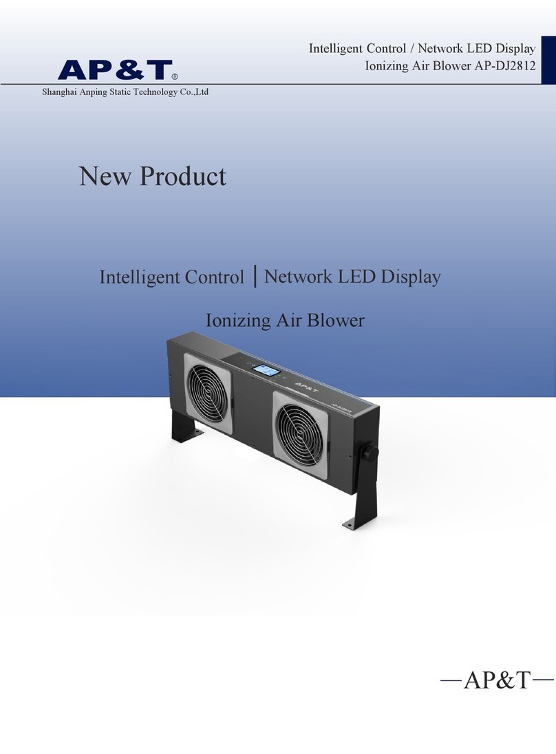
Ionizing Air Blower AP-DJ2813
Shanghai Anping Static Technology Co.,Ltd
AP&T
R
AP&T
New Product
Intelligent Control Network LED Display
Ionizing Air Blower

Effectively solve the problems
caused by static electricity
Suitable for electronics, optoelectronics,
semiconductor and other industries
Static removal Prevent blockage of feeder
Prevent static electricity
Prevent material splash
Prevent adhesion of objects

Network Monitoring
Monitoring the working status of
ionizing air blower online
RS485
communication
AP-DY6703
AP-KT3701 AP-DY6704
USB wire link
USB wire link
IMS monitoring software

Cleaning time /Air volume output/Ion balance adjustable
CTTH → +/-
CFM → +/-
IBN→ +/-
CAL → OK
CAL →
Cleaning time setting
Set a reminder for the cleaning time at will. Blue light flashes indicates cleaning is required. The electrode needle
cleaning cycle should be set according to the working environment when using the ionizing air blower. Cleaning cycle
should be shorten appropriately in environment with more moisture and dust.
Air volume output adjustable
Fan speed in five gears. Adjust the air volume according to the installation distance of the static eliminator and the
status of the target object.
Ion balance adjustable
The ion balance voltage can be adjusted by adjusting the negative high voltage
amplitude remotely.
Intelligent Remote Control
TIME TIME
Reduce the negative high voltage amplitude,
the negative ion output decreases
Adjust ion balance voltage
Function Symbol Operation instructions
Button Function instructions
Unlock
Run / Pause
Clean
Adjust clean time
Adjust air volume
Adjust ion balance
Confirm
Reset
Unlock before adjusting operating parameters; 30s delay if any key is
pressed, exit and re-locked if no key is pressed.
Device starts running when power is on. Press "STOP" to standby and no
high voltage output. Press "RUN" again and the device will start working.
Press the button to clean the needle once.
Press CTTH first, and then press +/- to increase or decrease the
cleaning cycle. Minimum adjustment unit 1H.
Press CFM first, then press +/-,air volume from high to low is 1,2,3,4,5.
Press IBN first, then press +/- to adjust the ion balance voltage.
Note: Press CAL first, then press OK to confirm after adjusting the
output parameter; otherwise, false alarms are likely to occur.
Reset(150Hz、50%、4H):Press CAL first,then pressPress IBN first, then press + when the positive voltage on flat panel charge detector or object surface is high, press IBN first, then press - when
the negative voltage on flat panel charge detector or object surface is high until the ion balance reaches the ideal status.
Pulse DC method generate ions with two polarity by
applying "+" and "-" high voltage alternately on
positive and negative electrode needles.
Compared with power frequency AC method, the
utilization rate of ion generation is higher. And its
static elimination ability can be exerted no matter
in short or long distance. In addition, the
discharge frequency can be adjusted, which can
extend the discharge distance. The output ratio of
positive and negative ions can be adjusted, which
is convenient for intelligent control.
Decrease Tp so that the positive voltage acting capacity becomes smaller and the acting
time becomes shorter. Less positive ions and more negative ions output to neutralize
the excess positive charge on the surface of the object.
Increase Tp so that the positive voltage acting capacity becomes greater and the acting
time becomes longer. More positive ions and less negative ions output to neutralize the
excess negative charge on the surface of the object.
Adjust the duty ratio [Tp/(Tp+Tn)] to an appropriate ratio and send out the same amount
of positive and negative ions to neutralize the static electricity on the surface of the
object.
3 situations of static electricity on
the surface of the object
AC
High voltage power supply
Power frequency AC
T
+HV
-HV
Pulse DC
Pulse DC
Positive pulse Negative pulse
T
Pulse DC
+HV
-HV
Pulse DC
Discharge effect is better compare to
frequency AC ionizing air blower
Pulse DC VS Traditional AC
(Positive high voltage)
(Negative high voltage)
Positive voltage working time
Negative voltage working time

Keep a clean production environment and stay
away from static electricity
High Efficiency Static Removal
-400 -250 -125 01 25 250 400
900
750
600
450
300
150
0.3
0.8
1.3
1.9
2.4
2.9
3.4
3.9
4.4
5.0
5.5
6.0
6.5
Discharge Time(s)
-400 -250 -125 0 125 250 400
900
750
600
450
300
150
-5
-4
-3
-1
0
1
3
4
5
6
8
9
10
Ion Balance(V)
-400 -250 -125
Z(mm)
450mm
900mm
600mm
750mm
4000 125
X(mm)
150mm
300mm
250
Discharge time distribution diagram of AP-DJ2813 Ion balance distribution diagram of AP-DJ2813
Test Length (mm) Test Length (mm)
Note:The 0 point of the test length is the center position of the air blower
Test standard:ANSI/ESD.STM3.1,SJ/T 11446—2013
Test instrument: Trek charge plate tester
Test voltage:±1000V → ±100V attenuation
Test environment:humidity 50±5%;temperature 23±3℃
Trek 150*150mm charge plate tester
Test bearing chart of air blower
Test Height (mm)
Test Height (mm)

No.1
No.3
No.4
Magnetic net cover
The power is cut off immediately and the fan is in
the standby (STOP) state when the net cover is
separated , which is convenient for disassembly
and maintenance.
Built-in cleaning brush
Automatic needle brushing function when start
up. By default, the needle is automatically
brushed every 4 hours for manual cleaning and
maintenance free.
Fault alarm
Display screen show fault alarm and LED red
light alarm when the fan, ion balance, and high
voltage breakdown.
No.5
Network Monitoring
Wired network communication realisable
and monitor the working status of the air
blower.
RS485
communication
IMS monitoring software
No.2
High air volume fan five
speed adjustment
Stable performance and air volume output
1.45 times higher than ordinary fans.
Features
Safe / Easy to use / Durable

No.7
No.8
8 Tungsten electrode needles
Multiple air outlets, 8 needles per air outlet
with large amount of ion generation and
longer life time compared to titanium and
silicon.
CE certification
CE certified with electromagnetic protection function
and no electromagnetic interference to other
equipment. It can also effectively avoid external
electromagnetic interference affecting the normal
operation of the air blower which is a high-security
and high-reliability static eliminator.
No.9
No.10
Ion self balancing function
The self balancing range is ±10V and the
balance voltage can be displayed in real time.
Intelligent remote control
The negative high voltage amplitude is adjustable,
which can be used to adjust the ion balance voltage.
Ion output characteristics can be adjusted by remote
control.
±10V
No.6
LED display
LED display shows the equipment address (e.g.A00), wind
speed gear (e.g.S1), cleaning cycle (e.g.T04), temperature
and humidity, cleaning indication (Cleaning), fan fault
alarm (Fan Fault!!) and HV fault alarm (HV Fault!!). The
balance voltage of each air outlet displays in real time,
which alarms (Ion Fault!!!) when the set threshold is
exceeded, alarms fault when the high voltage is 0V.
Features
Safe / Easy to use / Durable

L-shaped bracket
Ground Stud
Three-in-one power switch
RJ45 power/communication interface
Power switch
Air volume adjustment
LCD display
Status Indicator
Front Back
Bakelite screw
handle(M5×8)
Panel functions
Cleaning switch
1、2 VCC:+24VDC
3 RS485+B
4 RS485+A
5 GND
6 GND
7
8
9 PE
LCD parameter display description
Display content Description Sample graph
RUN/STOP Run / Pause
A00 Current working address of the device:00
S4 Current wind speed gear:4
T04 Cleaning cycle:04(Unit:H)
F2 F1 Current air outlet (There are 1 to 4 air outlets for AP-DJ28
series ionizing air blower)
+07 -08 The balance voltage of the corresponding air outlet
28℃Temperature of the current operating environment
62%RH Humidity of the current operating environment
Cleaning... Cleaning indication
Fan Fault!!! Fan fault alarm
HV Warning!!! High voltage fault alarm
Green light:Running
Blue light:Pause / Standby
Blue light flashes:Cleaning
Red light:Fan fault alarm
Red light fashes:HV alarm
Product Use
Panel functions/specification/dimensions
Power interface cable function information
Orange/White-orange
Blue
White-blue
Green
White-green
Brown VTH:Sensor threshold alarm
HVAL:Eliminator high voltage alarm
White-brown Clean:Eliminator cleaning indication
Metal shield
ACT:Sensor/eliminator power-on indication
The output wiring diagrams of pins 7 and 8 are as follows:
HV Alarm signal:Normal--always open、Abnormal--always close
Power signal :Normal--always close
cleaning signal:Clean--always open

AP-DJ2813
DC 24V(RJ45 interface)/ Three in one socket(220VAC 50/60Hz)
DC±4KV → ±6KV
33W
Pulse DC
Tungsten alloy
750*550mm(L*W)
≤ 135CFM*3
Single air outlet≤ 58dBA(1000mm away from the air outlet)
≤ 0.05ppm(150mm away from the air outlet)
≤ |±15V|
≤ 2.5S(450mm away from the air outlet)
Balance voltage exceed alarm-red light flashes;
RS485
RS485(115200bps,8,1,n,n)≥ 20ms
Collector open circuit:< 50V,100mA
0℃ -50℃
< 70%RH
760*154*70mm(Ionizing Air Blower body size)Aluminum powder spraying
1 pair of L-shaped iron powder spraying mounting brackets, 1 pair of
bakelite screw handles(M5×8)
INPUT:AC100—240V 50/60Hz;
(This is preferred for simultaneous power supply)
Net weight(Including
power cord and bracket) 3.65KG
1Year
CE
Specification
Installation accessories
1 pair of L-shaped aluminum powder
spraying mounting brackets,
1 pair of bakelite screw handles(M5×8)Unit:mm
Dimensions
49
13
30
通
65
150
165
2-R6
1,5
85°
Model
Input voltageInput voltage
Output voltage
Power
Ion emission
Emitter electrode
Discharge range
Air volume
Noise
Ozone thickness
Ion balance
Discharge speed
Status indicator
Communication method
Signal output
Working temperature
Working humidity
Dimensions(L*W*H)Shell material
Installation accessories
Power adapter
Warranty
Certification
Power on/clean operation—blue light flashes;
Normal work—green light (always under monitoring status);
Fan fault alarm—red light always on;
High voltage fault alarm-red light flashes;
Infrared debugging/cleaning prompt-blue light flashing
OUTPUT:DC24V 2A(dual RJ45 interface)
70
154
760
786
125 250 250 125
77
750
192

1. Install the ionizing air blower and the matching power adapter firmly in the best discharge position.
2. Insert the power network cable into the adapter and the ionizing air blower RJ45 network port, and insert the three-phase power cable of the
adapter into the row socket.
3. The overhead air blower can also be directly powered by 220VAC. The actual power supply is 220VAC when both 220VAC and 24VDC are
connected to the fan.
4. Touch the power switch on the front panel of ionizing air blower. It will automatically brush the needle after starting and the fan works normally
when the indicator light is green.
Installation steps
Technical tips
Wall
Packing accessories
AP2930003 18YXG25110 18WXI000041AP2253011 1
Products Use
Installation steps/technical tips/Packing accessories
1. Place the ionizing air blower in the work area where static electricity is to be eliminated and the installation angle is perpendicular to the surface
of the charged body.
2. Ionizing air blower should be at least 300mm away from the metal conductor and metal grounding body. The ionizing air blower must be
reliably connected to the ground wire.
3. Two ionizing air blowers should be installed side by side with an interval of more than 400mm and more than 200mm away from obstacles such
as walls.
4. The air inlet is at least 150mm away from the wall.
Part namePicturePart No.SpecificationQ'TYPower adapterGRT-240200:DC24V 2A,Dual-port output,size:123*61*40.5mm(L*W*H)National standard power cordStandard 1.8m,Optional 3m/5m
Power cableStandard 2.5m,Optional 5m/10m
Remote controlIR remote control,84×38mm
Wall Wall
Wall Wall
400
Wall Wall

NO
1
2
3
4
Ion balance alarm Use the remote control to re-adjust after cleaning the
electrode and net cover
5
6
Return to factory for maintenance
Poor grounding / no grounding / chip damage
caused by wrong power supply circuit
7
Return to factory for maintenance
8Return to factory for maintenance
1. Please read the instruction manual carefully before installing and using this equipment.
2. The whole set of equipment must be reliably grounded during use, and the connection resistance of the electrical connection to the AC
equipment ground should be less than 1 ohm.
3. Do not use this equipment in environment where humidity is > 70%..
4. It is strictly forbidden to use this equipment in flammable and explosive environments.
5. Unauthorized disassembly of the product is strictly prohibited, internal maintenance and repair must be performed by professionals.
6. The product is strictly prohibited to touch liquid during use, otherwise an abnormality may occur and cause electric shock or fire.
7. Power must be turned off during inspecting or replacing the product, otherwise it may cause electric shock or fire.
8. The product is specially designed to eliminate static electricity. It is strictly forbidden to use it for other purposes. Any abnormal use may
cause machine failure, electric shock, fire and other accidents.
9. It is strictly forbidden to touch the electrode needles when power is on, otherwise it is easy to cause malfunctions and electric shock
accidents.
10.The electrode needle is a sharp metal object, please use it with care.
11. Please check the specifications of the power supply before powering on the product. Any power supply that does not meet the
specifications will cause damage to the product.
12.Please check the product power cord/communication cord regularly and replace it immediately if it is damaged. Otherwise it is easy to
cause problems such as electric leakage, poor communication, and abnormal operation.
Safety warning
Faults
The indicator on the fan
panel is off
The electrostatic removal
performance decreased
obviously.
The electrostatic removal
performance decreased
High voltage/ion balance
alarm(Panel indicator light
flashes red)
Fan alarm(Panel indicator red
light always on)
Unable to discharge
The display is off or flickering
The product is smoky or burnt
Reasons Solutions
Trouble shooting
Poor contact of the power cable
Power supply mismatch
Check whether the power cable is in good condition and
securely connected
Confirm the power supply specification(INPUT:100—240VAC
50/60Hz;OUTPUT:24VDC 2000mA)
Discharge needle is polluted and damaged Clean or replace the discharge needle
The cleaning brush covers the electrode needle Brush the needle manually with the remote control, or shut down and
restart to keep the cleaning brush away from the electrode needle
Ionizing air blower is set incorrectly Confirm the best installation location
There are conductors or other
ionizing air blower around Remove (moving) conductors or other ionizing air blowers
Electromagnetic interference
Abnormal discharge
No power supply for high voltage module
High voltage module is damaged
Turn off the power switch / unplug the power cable, restart
the ionizing air blower
Confirm whether the electrode needle is close to or touching
the metal conductor, and remove foreign objects
Return to factory for maintenance
Fan fault
The fan power supply or control circuit is damaged
Main-board chip is damaged
High voltage module is damaged
Abnormal discharge
High voltage module is damaged
Poor grounding or wrong product power supply circuit
The high-voltage module is damaged or the insulation
of the discharge bracket is damaged
Check the grounding of the ionizing air blower and plant equipment,
and return to the factory for maintenance
Check the grounding of the ionizing air blower and plant equipment,
and return to the factory for maintenance
Return to factory for maintenance
The cleaning brush covers the electrode needle Brush the needle manually with the remote control, or shut down and
restart to keep the cleaning brush away from the electrode needle

1. The fan should be cleaned and maintained in time according to the use environment and the required electrostatic protection requirements
in order to ensure the good performance of the product. That is, gently remove the dust on the electrode, discharge bracket, fan and metal
mesh cover with electrostatic brush, dust-free cotton swab, dust-free cloth dipped in anhydrous alcohol. Note:
A. Operation must be done 10 minutes after power cut of
B. The cleaning cycle of the electrode needle should be set according to the working environment during use of the fan. It should be
appropriately reduced in the environment with more humid and dusty.
C. The fan must be powered on after alcohol is completely volatilized after cleaning. No other organic solvent can be used to clean the fa
D. The alloy electrode is a consumable product which is not included in the scope of warranty and will be charged for replacement when
repairing.
2. Do not press or rotate the control buttons on the fan panel too hard; otherwise, the device will be permanently damaged.
3. If the working indicator light on the front panel of the fan is off or red, it should be stopped and repaired by professional maintenance
personnel. It can be used only after the electrical performance index is normal.
Maintenance
After-sales service
AP-DJ2813 ionizing air blower has undergone rigorous testing and aging treatment before ex-work. Its performance has completely reached
the relevant indicators marked in the usage instruction.
AP&T makes a commitment to the customer that any defective parts inspected by AP&T will be repaired or replaced free of charge within one
year from the date of purchase. However, this commitment does not apply to:
1. The device is incorrectly used or installed.
2. Damage caused by negligence or accident during use;
3. Modified, disassembled or repaired by other service departments not authorized by Anping Company.
AP&T shall not be liable for any incorrect use of the products except for repair or replacement of parts as specified above.

AP&T
专业创造价值
Professional electrostatic intelligent monitoring/analysis
and elimination solution provider
Speciality Creates Value
AP&T
Shanghai Anping Static Technology Co.,Ltd
Tel : +86-21-64517676
Fax : +86-21-64517673
Postcode : 200233
Website : www.ap-static.com
Address : 3/F,Building 27,No.69,Guiqing Road,Shanghai,China
Table of contents
Other AP&T Blower manuals

AP&T
AP&T AP-DC2452-60C User manual

AP&T
AP&T AP-DC2451-001 User manual

AP&T
AP&T AP-DC2451-001 User manual

AP&T
AP&T AP-DJ1802 User manual

AP&T
AP&T AP-DJ1811 User manual

AP&T
AP&T AP-DJ2811 User manual

AP&T
AP&T AP-DJ2812 User manual

AP&T
AP&T AP-DJ2814 User manual

AP&T
AP&T AP-DC2453 User manual

AP&T
AP&T AP-AC2459 User manual
Popular Blower manuals by other brands

Badger Basket
Badger Basket 2060 Series II Operator's manual

Makita
Makita XBU02 instruction manual

Ikra
Ikra BVN 2200 operating instructions

CleanCraft
CleanCraft HKM 700 operating instructions

Black & Decker
Black & Decker Leaf Hog 617365-00 instruction manual

Cincinnati Fan
Cincinnati Fan CPF Installation, safety, operation & maintenance manual amd parts list