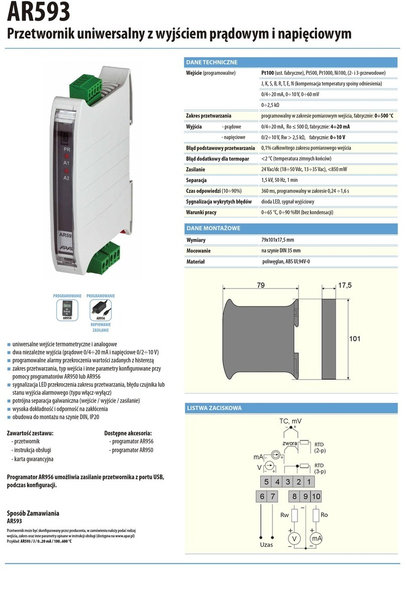
APAR AR594 Installation instructions

USER INSTRUCTION
UNIVERSAL TRANSDUCER
AR594
Version 2.0.1
2016.03.01
APAR
-
SALES OFFICE
05-090 Raszyn, ul. Gałczyńskie o 6, Poland
Tel. +48 22 101-27-31, +48 22 853-49-30
E-mail: automatyka@apar.pl
Website: www.apar.pl

2
Thank you for choosing our product.
These instructions will facilitate operating the device and enable safe use of the device at its full
capacity.
Prior to the installation and startup of the device, please become familiar with these
instructions.
In the event of any additional questions, please contact our technical adviser.
CO TE TS
1. SAFETY PRI CIPLES..................................................................................................................................... 3
2. I STALLATIO GUIDELI ES....................................................................................................................... 3
3. GE ERAL CHARACTERISTICS OF THE TRA SDUCER ............................................................................ 3
4. CO TE TS OF THE SET ............................................................................................................................... 4
5. TECH ICAL DATA......................................................................................................................................... 4
6. E CLOSURE DIME SIO S A D I STALLATIO DATA .......................................................................... 5
7. DESCRIPTIO OF TERMI AL STRIPS A D ELECTRICAL CO ECTIO S ............................................ 6
8. LOCATIO A D DESCRIPTIO OF ELEME TS OF THE FRO T PA EL ............................................... 6
9. SETTI G OF THE CO FIGURATIO PARAMETERS ................................................................................. 7
10. CO FIGURATIO OF THE ALARM OUTPUT .......................................................................................... 9
11. SIG ALI G OF MEASUREME T ERRORS .............................................................................................. 9
12. RS485 COMMU ICATIO I TERFACE (acc. to EIA RS-485). ............................................................ 10
13. RS232C COMMU ICATIO I TERFACE (acc. to EIA RS-232C) ........................................................ 10
14. MODBUS–RTU SERIAL TRA SMISSIO PROTOCOL ......................................................................... 10
15. CO ECTI G THE CO TROLLER TO A COMPUTER A D AVAILABLE SOFTWARE....................... 11
16. USER'S OTES .......................................................................................................................................... 12
Please pay particular attention to t e text marked wit t is sign.
T e manufacturer reserves t e rig t to make c anges to t e design and t e programming of t e device wit out
any deterioration of t e tec nical parameters (some functions may not be available in older versions).
!

3
1. SAFETY PRINCIPLES
before you start to use t e device, become familiar wit t e present instructions;
in order to avoid electrocution or damage to t e device, its mec anical and electrical installation
must be performed by qualified staff;
before switc ing on t e power supply, make sure t at all cables and wires are properly connected;
before making any modifications to t e wire and cable connections, switc off t e device's power supply;
ensure proper operating conditions compliant wit t e tec nical specification of t e device (power supply
voltage, umidity, temperature - see c apter 5).
2. INSTALLATION GUIDELINES
T e device is designed so as to ensure an appropriate level of immunity to most interferences t at may occur in
industrial environments. In environments of unknown level of interferences, it is recommended to implement t e
following measures so as to prevent potential interference wit t e operation of t e device:
do not supply t e device from t e same lines as ig -power equipment wit out using appropriate power
line filters;
use cable s ields on power supply cables, sensor cables, and signal cables, w ereby t e eart ing of t e s ield
s ould be single-point and located as close to t e device as possible;
avoid running instrument (signal) cables in t e direct vicinity of and parallel to power distribution and power
supply cables;
it is recommended to use twisted pair signal cables;
in t e case of sensing resistors in 3-wire connections, use identical wires;
avoid locating remotely controlled, electromagnetic meters, and ig -power loads, loads wit p ase or group
power control, and ot er devices producing large impulse interferences close to one anot er;
ground or zero metal rails on w ic rail-mounted devices are installed.
3. GENERAL CHARACTERISTICS OF THE TRANSDUCER
linear processing of measured temperature or anot er p ysical value transformed into a digital signal;
ig accuracy, long-term stability, and immunity to interferences;
universal input:
- t ermoresistance... Pt100, Ni100, Pt500, Pt1000
- t ermocouple ..................... J, K, S, B, R, T, E, N
- analog ....................... 0/4÷20mA, 0÷10V, 0÷60mV, resistance 0÷2500o m
digital serial interface (RS232 or RS485, MODBUS-RTU protocol)
triple galvanic isolation (input/output/supply)
narrow enclosure for installation on t e TS35 rail (DIN rail)
scope of processing, input type, and ot er parameters configured wit :
- ARSOFT-CFG series software and t e AR956 programmer;
- a user application;
- an autonomous AR950 programmer;
a programmable exceeded processing range and set value alarm wit ysteresis (type on/off, OC output)
LED signaling of exceeded processing range, sensor error, or alarm output status (on/off type)
ig accuracy and immunity to interferences;
available ARSOFT-CFG series software t at enables visualization and recording of measurements
!
!

4
NOTE:
−before starting to work wit t e meter, you must become familiar wit t is using instruction, properly
prepare t e electrical system and t e mec anical system, and correctly configure t e parameters;
−if t e c aracteristics of t e transducer are configured wit t e AR956 programmer, t e transmission
parameters t at must be set in t e options of t e ARSOFT-CFG, software, at t e time of first
connection (default parameters) are t e following:
−COM port number: assigned by t e Windows system after installation of t e AR956 controller,
available in t e “Device Manager” in t e “Ports (COM and LPT)” group; see “Quick start
programmer AR956”
−transmission speed: 2,400 bit/s
−MODBUS address = 1
A detailed description of t e configuration parameters of t e transducer can be found in c apter 9.
4. CONTENTS OF THE SET
a transducer wit a set of connections;
a user instruction;
a warranty card.
5. TECHNICAL DATA
1 universal programmable input
measurement range
-
Pt100 (RTD, 3
-
or 2
-
wire)
-
200
÷
850
°C
-
Ni100 (RTD, 3
-
or 2
-
wire)
-
50
÷
170
°C
-
Pt500 (RTD, 3
-
or 2
-
wire)
-
200
÷
850
°C
-
Pt1000 (RTD, 3
-
or 2
-
wire)
-
200
÷
850
°C
-
t ermocouple J (Fe
-
CuNi)
-
40
÷
800
°C
-
t ermocouple K (NiCr
-
NiAl)
-
4
0
÷
1,200
°C
-
t ermocouple S (PtR 10
-
Pt)
-
40
÷
1,600
°C
-
t ermocouple B (PtR 30PtR 6)
300
÷
1,800
°C
-
t ermocouple R (PtR 13
-
Pt)
-
40
÷
1,600
°C
-
t ermocouple T (Cu
-
CuNi)
-
25
÷
350
°C
-
t ermocouple E (NiCr
-
CuNi
)
-
25
÷
740
°C
- t ermocouple N (NiCrSi-NiSi
)
-
35
÷
1,300
°C
-
current (R
in
= 110 Ω)
0/4
÷
20
mA
-
voltage (R
in
= 100 kΩ )
0
÷
10
V
-
voltage (R
in
> 5 MΩ)
0
÷
60
mV
-
resistance (3
-
or 2
-
wire)
0
÷
2,500
Ω
Permissible feed resistance
(RTD, Ω)
R
d
< 30 Ω (for eac line)
Resistance input current
(RTD, Ω) 180 ÷ 250 μA
Digital output
RS485 or RS232
Transmission protocol
MODBUS-RTU, SLAVE
C aracter recording format
8N1 (8 bits, 1 stop bit, no parity bit)
Transmission speed
(bit/s)
600, 1200, 2400, 4800, 9600 14400, 19200, 38400
!

5
Transmission signaling
Red LED diode (Rx/Tx)
Alarm output
12 V, bistate type OC (open collector, NPT transistor),
current limiting resistance 440 Ω
Processing err
ors
(at ambient temperature of 25 °C):
-
basic
-
for RTD, mA, V, mV, Ω
0.1% of t e measurement range ±1 digit
-
for t ermocouples
0.2% of t e measurement range ±1 digit
-
additional for t ermocouples
<2 °C (temperature of cold tips)
-
additional fr
om ambient temperature c anges
< 0.01% of t e input range /°C
Resolution of measured temperature
programmable, 0.1 °C or 1 °C
Resolution of analog input
(programmable)
-1999 ÷ 9999 (parameters
3: Abot , 4: Atop
)
Response time
(10 ÷ 90%)
135 ÷ 1500 ms
(programmable wit
parameter 1: FiLt ), factory 270 ms
Power supply
(Usup)
24 VAC/DC (18÷50 VDC, 14÷35 VAC)
Power consumption
< 500 mW
Operating temperature range
0 ÷ 65 °C
Relative umidity range
0
-
90 °C (no condensation)
Protection rating
IP20
Ope
rating position
any
Weig t
approx. 70 g
Separation (in/out/sup)
1.5 kV, 50 Hz, 1 min.
Electromagnetic compatibility (EMC)
immunity: according to t e PN
-
EN 61000
-
6
-
2:2002(U)
standard
emissivity: according to t e PN
-
EN 61000
-
6
-
4:2002(U)
standard
Transm
ission parameters for t e AR956 programmer
Factory: 2400 bit/s, address MODBUS = 1
(parameter 12: Addr=1 and 13: br=2, see c apter 9)
NOTE:
Measurements performed by t e transducer w en supplied from t e AR956 programmer are not reliable.
T e AR956 programmer is intended only to supply t e transducer during configuration of parameters using t e
ARSoft-CFG software. During normal operation, t e transducer s ould be supplied in t e standard manner.
6. ENCLOSURE DIMENSIONS AND INSTALLATION DATA
Enclosure type
rail
-
mounted
Material
polycarbonate, ABS UL94V
-
0
Enclosure dimensions
79 x 101 x
17.5 mm
Fixing met ods
on a 35 mm DIN rail
Conductor cross-
sections
2.5 mm
2
(supply, outputs),
1.5 mm
2
(inputs)
!

6
Table 7. Numbering and description of terminal strips.
Terminals
Description
1-2-3
input Pt100, Ni100, Pt500, Pt1000, resistance, (2
-
and 3-wire RTD)
2-3
t ermocouple input TC (J, K, S, B, R, T, E, N) and
voltage input 0÷60 mV
3
-
5
current input 0/4÷20 mA
4
-
5
voltage input 0÷10 V
6
-
7
power supply input 24 VAC/DC
8
-
9
-
1
0
input RS232C or RS485
11
-
12
alarm output (on/off type)
Usup - power supply voltage
OC - output of t e open collector type, NPN transistor
JP1 - a clamp terminating t e lines of t e RS485 interface wit a 120 Ω
resistor (termination switc ed on w en JP1 is closed)
8. LOCATION AND DESCRIPTION OF ELEMENTS OF THE FRONT PANEL
Table 8. Description of t e elements of t e front panel.
Symbo
l
Description
PR
programming socket (do not use during transmission
from devices connected to t e RS232C line or t e
RS485 line of t e AR594 transducer)
A
LED signaling of exceeded processing range,
sensor error, or OC alarm output status
Rx/Tx
LED sig
naling of serial transmission
NOTE:
Connecting ot er devices t an t e AR950or AR956 programmer to t e PR socket may result in damage to
t e connected device and t e AR594 transducer.
7. DESCRIPTION OF TERMINAL STRIPS AND ELECTRICAL CONNECTIONS
!

7
9. SETTING OF THE CONFIGURATION PARAMETERS
All t e configuration parameters of t e device are stored in t e non-volatile internal memory.
W en t e device is switc ed on for t e first time, an error may occur due to t e lack of a sensor or t e fact t at t e
sensor t at is connected is not one t at is factory-programmed. In suc a situation, t e appropriate sensor or
analog signal s ould be connected or t e parameter configuration must be performed.
T ere are two parameter configuration met ods:
1.
Use t e RS232C, RS485 or PRG interface (AR956 programmer) and t e ARSOFT-CFG software:
−connect t e device to a computer port and to start and configure t e ARSOFT-CFG application
−after t e connection as been establis ed, t e current measured value is displayed in t e window of t e
software
−setting and viewing of t e device parameters is possible in t e parameter configuration window
−new parameter values must be approved wit t e Appr ve changes button
−t e current configuration can be saved in a file or set using values read from a file
NOTE:
−before disconnecting t e device from a computer, press t e Disc nnect device button (ARSOFT-CFG)
−in t e event of no response:
-in t e Pr gram pti ns c eck t e configuration of t e port and t e MODBUS address f the
device
-make sure t at t e serial port drivers in t e computer ave been properly installed for t e RS485
converter or t e AR956 programmer
-disconnect for a few seconds and t en reconnect t e RS485 converter or t e AR956
programmer
-restart t e computer
-if t e AR955 programmer is used instead of t e AR956 programmer, connect t e power supply
voltage to t e transducer
2.
Use t e autonomous AR950 programmer to:
−connect t e power supply voltage to t e transducer;
−use t e cable included in t e set to connect t e AR950 programmer to t e device being configured (an
AR5xx series transducer);
−t e programmer can be connected bot before t e power supply is switc ed on and during operation of
t e device;
−enter t e configuration parameters programming mode by pressing (for about 2 s) t e CONF button until
t e ConF message briefly appears on t e display and t en t e mnemonic name of t e first parameter is
displayed ( inP ); by pressing t e
▲
button, you can move to t e next parameter, and by pressing t e
▼
button - to t e previous parameter ( inP ↔ FiLt ↔ dot ↔…); a list of configuration parameters can be
found in t e user instruction of t e device being configured;
−in order to c ange or view t e value of t e current parameter, press SET (edition of t e parameter);
−by using
▲
or
▼
, you can c ange t e value of t e current parameter;
−by pressing SET again, you can save t e edited value and return to t e parameter name display (e.g. FiLt );
−in t e parameter edition mode, by pressing ESC for a s ort time, you can cancel t e c anges and return to
t e parameter name display mode;
−you can exit t e configuration parameters programming mode by pressing t e ESC button for a long time
(approx. 1 s); ot erwise, t e mode is switc ed off after approx. 2 minutes;
−in t e normal mode, t e measured value is displayed;
Detailed information can be found in t e user instruction of t e AR950 programmer.
!

8
In t e event of indications different t an t e actual value of t e input signal, t e zero and t e sensitivity of a
sensor can be tuned: parameters 10: cALo (zero) and 11: cALG (sensitivity).
In order to restore t e default settings, use t e file wit t e default configuration in t e ARSOFT-CFG software.
NOTE:
T e default transmission parameters for t e AR956 programmer in t e ARSOFT-CFG software are t e following:
2400 bit/s, address MODBUS = 1
Table 9. List of configuration parameters
Parameter Range of variability of t e parameter and description
Default
settings
0: inP
Type of measurement input
0: Pt100 t ermoresistance sensor (RTD) Pt100 (-200 ÷ 850°C)
Pt100
1: ni100 t ermoresistance sensor (RTD) Ni100 (-50 ÷ 170°C)
2: Pt500 t ermoresistance sensor (RTD) Pt500 (-200 ÷ 850°C)
3: Pt1000 t ermoresistance sensor (RTD) Pt1000 (-200 ÷ 850°C)
4: tc-J t ermoelectric sensor (t ermocouple) type J (-40 ÷ 800°C)
5: tc-K t ermoelectric sensor (t ermocouple) type K (-40 ÷ 1,200°C)
6: tc-S t ermoelectric sensor (t ermocouple) type S (-40 ÷ 1,600°C)
7: tc-b t ermoelectric sensor (t ermocouple) type B (-300 ÷ 1,800°C)
8: tc-r t ermoelectric sensor (t ermocouple) type R (-40 ÷ 1,600°C)
9: tc-t t ermoelectric sensor (t ermocouple) type T (-25 ÷ 350°C)
10: tc-E t ermoelectric sensor (t ermocouple) type E (-25 ÷ 740°C)
11: tc-n t ermoelectric sensor (t ermocouple) type N (-35÷ 1,300°C)
12: 4-20 current signal 4 ÷
20 mA
13: 0-20 current signal 0 ÷
20 mA
14: 0-10 voltage signal 0 ÷ 10 V
15: 0-60 voltage signal 0 ÷
60 mV
16: rES resistance signal 0 ÷
2,500 Ω
1: FiLt filtration (3)
1 ÷
10
digital filtration of measurements (response time) 4
2: dot position of t e
point/resolution(2)
0 no point or 1°C resolution for temperature 1
(0.1 °C)
1 0
.
0 or resolution 0.1 °C for temperature
3: Abot start of input scale (1)
/999 ÷ 9999
indication for 0/4mA, 0V, 0Ω on t e input - start of input scale 0.0 °C
4: Atop end of input scale (1)
/999 ÷ 9999
indication for 20 mA, 10 V, 60 mV, 2,500 Ω on t e input
-
end
of t e input scale 100.0 °C
5: out1 c aracteristics of t e
OC alarm output (c apter 10)
0: r tr exceeded range alarm
r tr
1: inu reverse ( eating)
2: dir direct (cooling)
6: s t1 OC output alarm
value
in t e measurement range of t e specific input type 50.0 °C
7. H2 ysteresis of t e OC
output 0.0÷999.9 °C or 0÷9999 units (1) 1.0 °C
8. bot1 start of scale for t e
exceeded range alarm in t e measurement range of t e specific input -199.9 °C
!

9
9. top1 end of scale for t e
exceeded range alarm in t e measurement range of t e specific input 999.9 °C
10: cALo calibration of t e
zero
zero offset for measurements: /00.0 ÷ 100.0 °C
or /000 ÷ 1000 units (1)
0.0 °C
11: cALG gain
-85.0 ÷ 115.0 %
calibration of inclination (sensitivity) for measurements
100.0 %
12: Addr MODBUS address of
t e device 1 ÷ 247 1
13: br transmission speed
[bps] 0=600, 1=1,200, 2=2,400, 3=4,800, 4=9,600, 5=14,400, 6=19,200, 7=38,400, 2 = 2400
Notes: (1) – applies to analog inputs ( mA, V, mV, Ω ),
(2) – applies only to display of data in t e connected programmer (AR950, AR956),
(3) – for Filt=1, t e response time is approx. 0.135 s; for Filt=10 - approx. 1.5 s. Hig er degree of filtration
means a more smoot measured value and a longer response time, w ic is recommended in t e case
of turbulent measurements (e.g. water temperature in a boiler).
10. CONFIGURATION OF THE ALARM OUTPUT
T e type of alarm c aracteristics for t e OC output is determined by parameter 5: oVt1 (see c apter 9, Table 9).
For oVt1=r tr, t e OC output is connected after t e measured value exceeds t e range defined by parameters 8:
bot1 and 9: toP1. In t is mode, t e alarm condition is additionally indicated by t e blinking of t e A LED diode on
t e front panel.
W en t e oVt1 parameter becomes equal to inu or dirparameter 6: SEt1 and 7: H1 apply, t e status of t e
output is indicated by t e A LED (it is on w en t e output is switc ed on).
T e principle of operation of t e OC output in t e individual operating modes is s own in t e figures below.
11. SIGNALING OF MEASUREMENT ERRORS
T e transducer detects t e following measurement errors:
- exceeded processing time, downward or upward (se c apter 10, figure a);
- connected sensor or input signal ot er t an t e one set in t e configuration parameters;
- defective sensor circuit.
Met ods of signalization of measurement errors:
- blinking of t e A LED (w en parameter 5: out1=0: r tr );
- measured value equal to -19999 or 19999 (see c apter 14, table 14.6, register address = 0).

10
12. RS485 COMMUNICATION INTERFACE (acc. t EIA RS-485).
T e installation specification for t e RS485 interface is t e following:
- maximum cable lengt - 1 km (observe t e installation guidelines, c apter 2);
- maximum number of devices in a RS485 line: 30, in order to increase t e number, use RS485/RS485 amplifiers;
- termination and polarizing resistors w en t e MASTER is at t e start of t e line (Fig. 12):
- at t e start of t e line - 2 x 820 Ω to t e ground and +5 V of t e MASTER and 150 Ω between lines;
- at t e end of t e line - 150 Ω between t e lines (or clamp JP1 closed, see c apter 7);
- termination and polarizing resistors w en t e MASTER is in t e center of t e line:
- at t e converter - 2 x 820 Ω, to t e ground and +5 V of t e converter;
- at bot ends of t e line - 150 Ω between t e lines (or clamps JP1 closed, see c apter 7).
Equipment from different manufacturers t at form t e RS485 network (e.g. RS485 converters/USB) may ave
integrated polarizing and terminating resistors; in suc a case t ere is no need to use external elements.
Fig. 12. Pictorial diagram of t e RS485 network
13. RS232C COMMUNICATION INTERFACE (acc. t EIA RS-232C)
Maximum cable lengt : 10 m.
Maximum number of devices connected to t e computer: 1.
14. MODBUS–RTU SERIAL TRANSMISSION PROTOCOL
C aracter format : 8 bits, 1 stop bit, no parity bit
Available functions : READ - 3 or 4, WRITE – 6, minimum query repetition period: 135 ms
Table 14.1. Claim frame format for t e READ function (frame lengt - 8 bytes):
address of
t e device
function
0x04
read register address: 0 ÷
19 (0x0013)
number of read registers:
1 ÷ 20 (0x0014) CRC c eck sum
1 byte
1 byte
2 bytes (HB
-
LB
)
2 bytes (HB
-
LB)
2 bytes (LB
-
HB)
Example 14.1. (readout of t e measured value, parameter 12: Addr=1): 0x01 - 0x04 - 0x0000 - 0x0001 - 0x31CA

11
Table 14.2. Claim frame format for t e WRITE function (frame lengt - 8 bytes):
address of
t e device
function
0x06 write register address: write register value CRC c eck sum
1 byte
1 byte
2 bytes (HB
-
L
B)
2 bytes (HB
-
LB)
2 bytes (LB
-
HB)
Example 14.2. Entry in a register wit address 10 (0xA) wit t e 0 value: 0x01 - 0x06 - 0x000A - 0x0000 - 0xA9C8
Table 14.3. Response frame format for t e READ function (minimum frame lengt - 7 bytes):
address of
t e device
function
0x04
number of bytes in t e
data field (max. 20*2=40
bytes)
data field - register value CRC c eck sum
1 byte
1 byte
1 byte
2 bytes (HB
-
LB)
2 bytes (LB
-
HB)
Example 14.3. Response frame for register value equal to 0: 0x01 - 0x04 - 0x02 - 0x0000 - 0xB930
Table 14.4. Response frame format for t e WRITE function (frame lengt - 8 bytes):
copy of t e claim frame for t e WRITE function (Table 14.2)
Table 14.5. Special answer (errors: function field = 0x84 or 0x83 in t e case of t e READ function and 0x86 in t e
case of t e WRITE function, Hig Byte in t e data field = 0):
Error code
(HB-LB in t e data field)
Error description
0x0001
non
-
existing register address
0x0002
erroneous value of parameter to be saved
0x0003
improper function number
Example 14.5. Error frame for a non-existing read register address:
0x01 - 0x84 - 0x02 - 0x0001 –0x5130
Table 14.6. Map of registers for t e MODBUS-RTU protocol
Register address
HEX (DEC)
Value
(HEX or DEC)
Description of register and access type
(R- read only register, R/W - read and write register)
0x00 (0) -19999 ÷19999
measured value
R
0x01 (1) and 0xC8 (200) 5940 device type identifier (AR594)
R
0x02 ÷ 0x05 (2 ÷5)
- reserved (do not use)
R
0x06 ÷ 0x13 (6 ÷ 19)
Reading/writing of parameter ( inp, filt, dot,…)
Register address = parameter number from Table 9
(c apter 9) + 6
R/W
15. CONNECTING THE CONTROLLER TO A COMPUTER AND AVAILABLE SOFTWARE
It may be useful (or necessary) to connect t e transducer to a computer in order to configure parameters, w ic
also enables copying t e setting to ot er transducers of t e same type.
As a standard, t e transducers are equipped wit a PR port, w ic enables connecting to a computer using an
AR956 programmer. Attention s ould be paid to t e configuration of transmission parameters in t e options of
t e ARSOFT-CFG software.
During t e first startup, t e (default) transmission parameters s ould ave t e following values:
Speed = 2,400 bit/s, MODBUS address = 1.
T e following applications are available (on a CD supplied wit t e AR956 programmer or to be downloaded from
t e Internet at www.apar.pl, Download section, for operating systems Windows Vista/7/8/10):

12
Name
Software description
ARSOFT-CFG
(free)
-
display of current measurement data from t e connected device
- configuration of t e type of measurement input, t e indication range, t e alarm options,
t e display, etc.
- creation of a disk wit a "cfg" extension, containing t e current configuration
of t e parameters to be used again (duplication of configuration)
- t e software requires communication wit t e device via t e PR port (AR956 or AR955)
T e detailed descriptions of t e aforementioned applications can be found in t e installation folders.
NOTE:
Before a connection is establis ed, make sure t at t e MODBUS address and t e transmission speed in t e options
of t e ARSOFT-CFG software are t e same as t e settings of t e device. Moreover, in t e ARSOFT software options,
set t e number of t e COM serial port in use (in t e case of t e RS956 or AR955 programmer it is t e number
assigned by t e operating system during installation of t e drivers).
16. USER'S NOTES
!
Table of contents
Other APAR Transducer manuals
Popular Transducer manuals by other brands

controlair
controlair 500-BD Installation, operation and maintenance instructions

S+S Regeltechnik
S+S Regeltechnik PREMASGARD 232 Series Operating Instructions, Mounting & Installation

B-K Medical
B-K Medical Convex Array 8803 user guide

B-K Medical
B-K Medical 8805 user guide

Metrix
Metrix 5485C installation manual

B-K Medical
B-K Medical 8848 user guide