APAR AR553 Installation instructions

APAR
-
Sales Office
05-090 Raszyn, ul. Gałczyńskiego 6
Tel. (+48) -101- 7-31, -853-48-56, -853-49-30
fax (+48) -101- 7-33
Internet: www.apar.pl, email: automatyka@apar.pl
USER INSTRUCTION
version version
without a display with an LCD display
TEMPERATURE TRANSDUCER
AR553
Version 3.0.0
017.04. 8

2
Thank you for choosing our product.
This instruction is intended to facilitate correct operation,
safe use, and taking full advantage of the device’s functionalities.
Before you start the device, please read and understand this instruction.
In the event of any additional questions, please contact our technical adviser.
CONTENT
1. AFETY PRINCIPLE ..................................................................................................................................... 3
2. IN TALLATION GUIDELINE ....................................................................................................................... 3
3. GENERAL CHARACTERI TIC OF THE TRAN DUCER ............................................................................ 3
4. CONTENT OF THE ET ............................................................................................................................... 4
5. TECHNICAL DATA......................................................................................................................................... 4
6. ENCLO URE DIMEN ION AND IN TALLATION DATA .......................................................................... 5
7. DE CRIPTION OF TERMINAL TRIP AND ELECTRICAL CONNECTION ............................................ 6
8. FUNCTION OF THE BUTTON ON THE CONTROL PANEL ................................................................... 7
9. ETTING OF THE CONFIGURATION PARAMETER ................................................................................. 7
10. ME AGE AND ERROR IGNALING ...................................................................................................... 9
11. CONNECTING THE CONTROLLER TO A COMPUTER AND AVAILABLE OFTWARE ......................... 9
12. R 485 COMMUNICATION INTERFACE (acc. to EIA R -485) ............................................................. 10
13. MODBU –RTU ERIAL TRAN MI ION PROTOCOL ( LAVE) .......................................................... 10
14. U ER' NOTE .......................................................................................................................................... 12
Please pay particular attention to the text marked with this sign.
The manufacturer reserves the right to make changes to the design and the programming of the device without
any deterioration of the technical parameters (some functions may not be available in older versions).
!

3
1. SAFETY PRINCIPLES
before you start to use the device, become familiar with the present instructions;
in order to avoid electrocution or damage to the device, its mechanical and electrical installation
must be performed by qualified workers;
before switching on the power supply, make sure that all cables and wires are properly connected;
before making any modifications to the wire and cable connections, switch off the voltage supplied
to the device;
ensure proper operating conditions compliant with the technical specification of the device (chapter 5,
power supply voltage, humidity, temperature).
2. INSTALLATION GUIDELINES
The device is designed so as to ensure an appropriate level of immunity to most interferences that may occur in
industrial and household environments. In environments of unknown level of interferences, it is recommended to
implement the following measures so as to prevent potential interference with the operation of the device:
a) do not supply the device from the same lines as high-power equipment without using appropriate
power line filters;
b) use shielded supply, sensor, and signal cables, whereby the earthing of the shield should be single-point
and located as close to the device as possible;
c) avoid running measurement (signal) cables in the direct vicinity of and parallel to power and supply cables;
d) it is recommended to twist the signal wires in pairs or to use a finished twisted-pair cable;
e) avoid proximity of remotely controlled devices, electromagnetic meters, high power loads, loads with phase
or group power control, and other devices that cause high impulse disturbances;
f) ground or zero metal rails on which rail-mounted devices are installed.
Make sure to remove the protective film from the LCD display before the first use of the device.
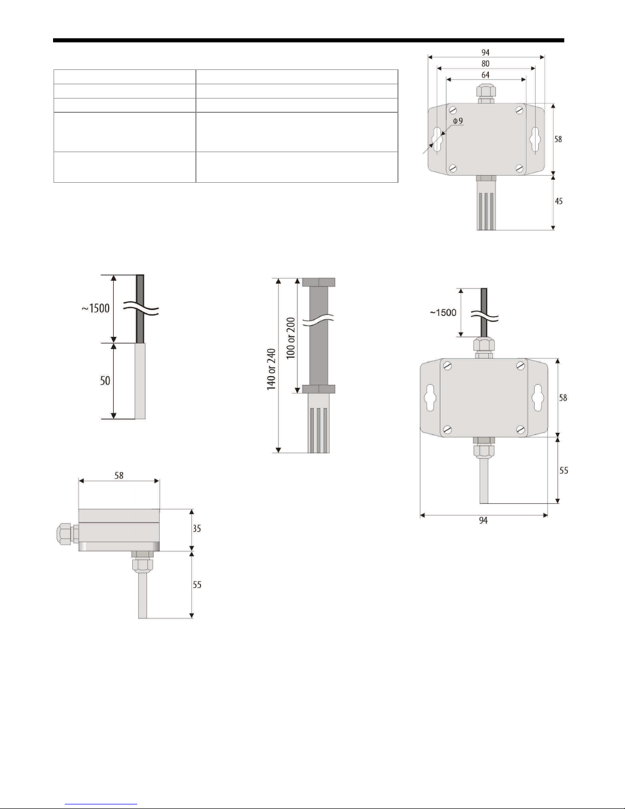
3. GENERAL CHARACTERISTICS OF THE TRANSDUCER
a probe integrated with the enclosure, external probe with a wire, external in the enclosure with a wire
or external on a stainless steel pipe
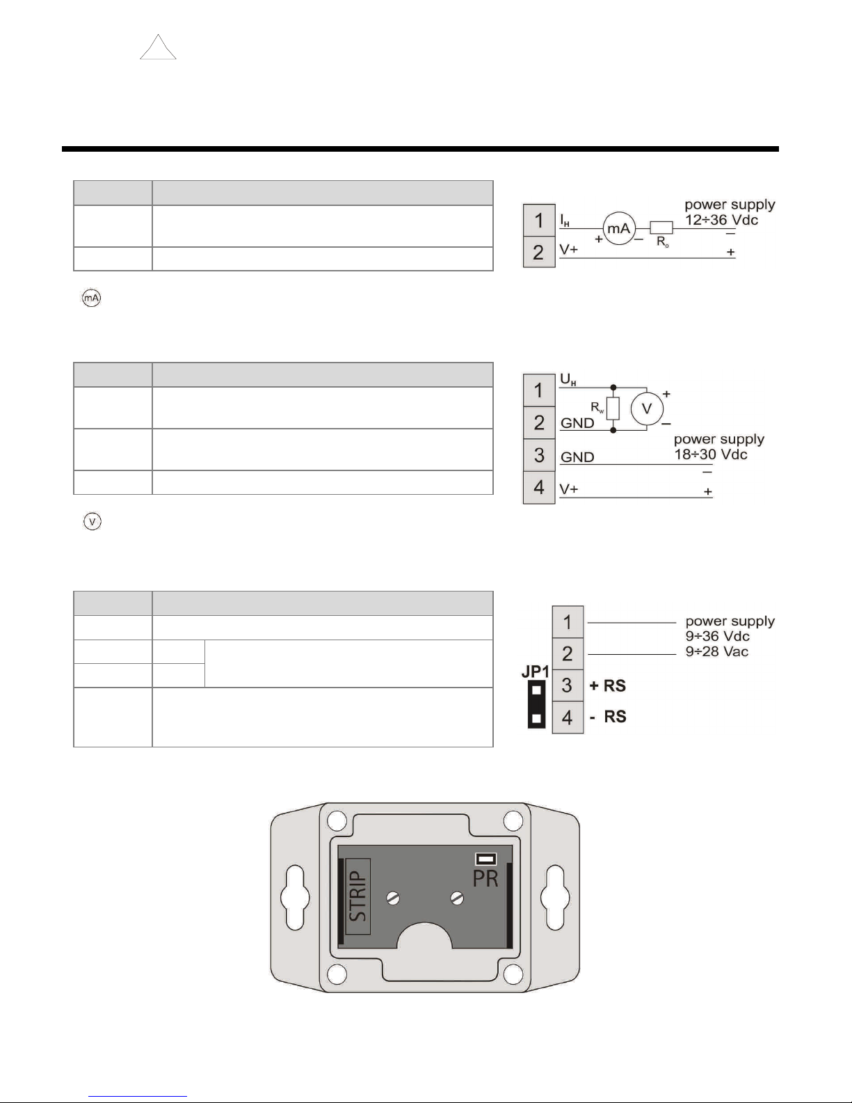
a current output 4- 0 mA ( -wire, with power supply from the current loop); a voltage output 0-10 V
(3-wire), or an RS485 interface
programmable processing ranges for temperature
without galvanic separations outputs/power supply
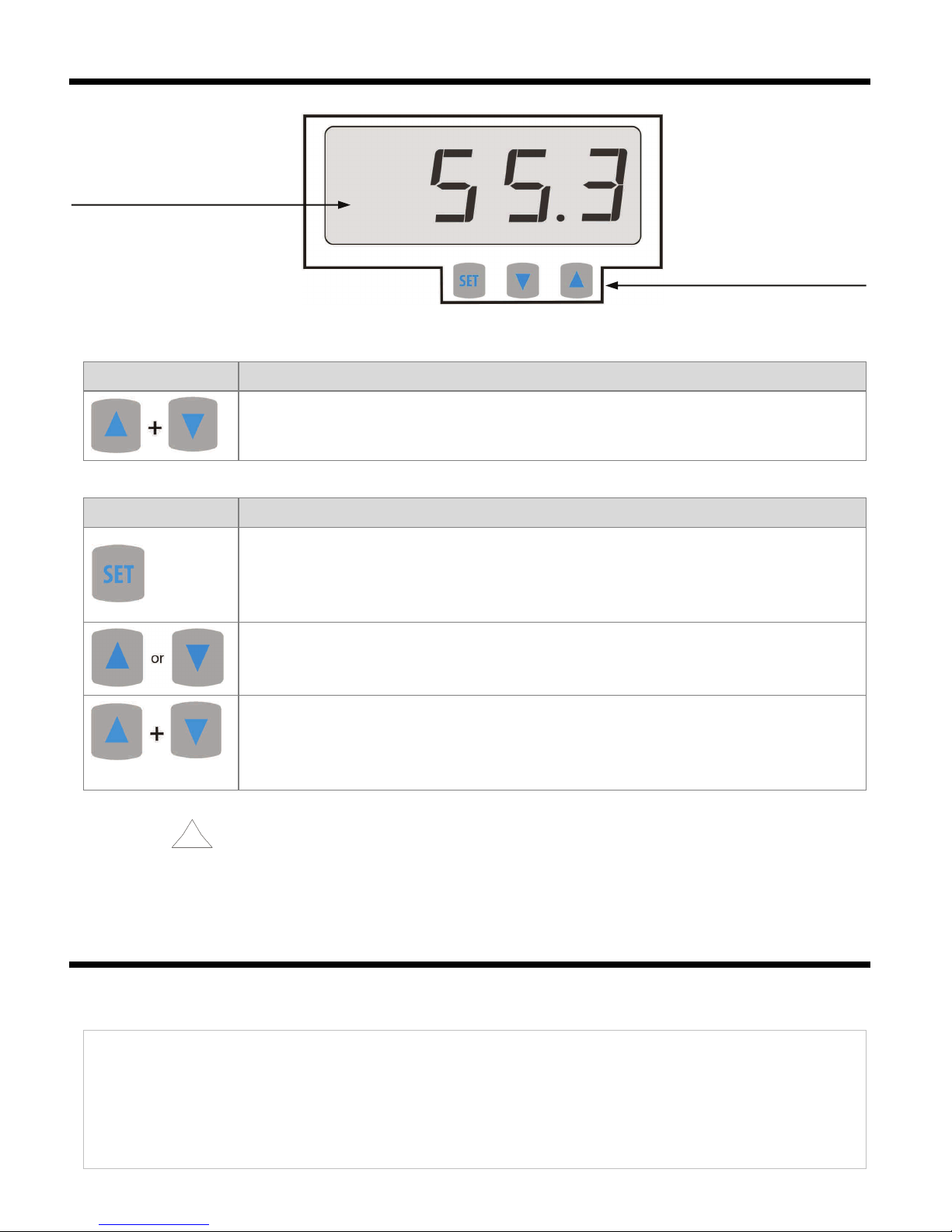
an LCD display with a keypad (option) that enables configuration of parameters;
configuration of parameters with the keypad, through the RS485 or PRG port (programmer AR956 or AR955)
and free ARsoft-CFG software that enables quick setting and copying of all configuration parameters
protection rating IP65 provided by the enclosure which improves reliability of operation thanks to high
resistance to penetration of water and dust and surface condensation of steam inside of the device
possible power supply from the programmer AR956 during configuration parameters
!
!

4
NOTE:
- before you s ar working wi h he device, become familiar wi h his user ins ruc ion and make sure he
elec rical and mechanical sys ems have been made properly and he correc parame ers have been se ;
- if he parame ers of he ransducer have been se using he AR956 programmer, he ARsof -CFG sof ware
mus be configured properly.
A de ailed descrip ion of he configura ion parame ers of he ransducer can be found in chap er 9.
4. CONTENTS OF THE SET
the transducer;
a user instruction;
a warranty card.
5. TECHNICAL DATA
Measuremen range
-
30÷80 °C (
-
50÷1 0 °C, only for external probe with
a
wire)
Processing range
programmable in measurement range, default
-
30÷60 °C
Measuremen accuracy
±0.5 °C in range
-
10÷85 °C, ± °C
remaining range
Measuremen resolu ion
0.1 °C
Measuremen period
1 s
LCD display (op ion)
4 digits,
1
0 mm high
Analog ou pu s
(without galvanic
separation from power
supply)
current 4
-
0 mA
maximum resolution approx. 14.5 µA;
load capacity R
o
< (Usup-1 ) / mA
voltage 0
-
10 V
max. resolution
~
9.1 mV, load capacity Io<4.5 mA (Ro> .5 k
Ω)
output error
basic < 0.1%;
additional ±0.01%/°C of the output range
Communica ion
in erfaces (RS485 and
PRG, do not use
simultaneously)
PRG programming
connection, standard
-
speed .4 kb/s (0.6÷115. kb/s for version with RS485 interface)
- character format 8N1 (8 data bits, 1 stop bit, no parity bit)
- MODBUS-RTU protocol (SLAVE)
- without galvanic separation from power supply
RS485, only in the RS
version
Power supply
version 4
÷
0 mA
1
÷
36 VDC (supply from the current loop)
version 0
÷
10 V
18
÷
3
0 VDC, current consumption without load on outputs:
approx. 7 mA (with and without an LCD)
version RS485
9
÷
8 VAC or 9
÷
36 VDC, current consumption approx. 5 mA (with
and without an LCD)
Ra ed opera ing
condi ions
without an LCD
-
30 to 80 °C
for humidity <100 %RH
(no condensation)
with an LCD
-
0 to 70 °C
Enclosure pro ec ion ra ing and moun ing
me hod
IP65,
wall mounted
Opera ing posi ion
any
Weigh
approx. 1 0 g (with integrated probe)
Elec romagne ic compa ibili y (EMC)
immunity: according to the PN
-
EN 61000
-
6
-
standard
emission: according to the PN
-
EN 61000
-
6
-
4 standard
!

5
6. ENCLOSURE DIMENSIONS AND INSTALLATION DATA
a) general data and dimensions of the standard version (integrated probe)
b) dimensions for external probes in different designs
b.1) An external probe with a wire b. .) A probe on a stainless steel pipe b.3) An external probe
AR553/ AR553/L150 or AR553/L 50 in an enclosure with a wire
AR553/3
b.4) A probe integrated with
the enclosure in the back
(channel) design AR553/T
c) installation of cabling
−cu off he power supply before making any changes o he cabling
−remove the 4 screws in the front cover and take it off the device
−in version with an LCD, carefully take out display from bolt connectors (perpendicularly to the front surface)
−terminals to connect power supply cables, outputs cables, and signal cables become accessible – see chapter 7
−the electric cables must be inserted into the enclosure through cable glands
−after the device has been mounted and the cabling has been installed, assemble the device carefully
performing the work in the reverse order
−in order to achieve the IP65 rating, the nuts of the cable glands and the enclosure cover must be tightened
precisely
Enclosure ype
industrial IP65
Ma erial
polycarbonate
Enclos
ure dimensions
58 x 94 x 35 mm
Fixing me hods
x Φ9 mm holes, distance between the
holes 80 mm, narrower part of the hook
holder with max. diameter of 5 mm
Conduc or cross-sec ions 1.5 mm

6
CAUTION:
In order o avoid any mechanical and elec ros a ic damage, one mus be very careful when handling he
circui board of he display.
Table 7.1. Numbering and description of terminal strips - the version with the current output
Terminals
Descrip ion
1
current output (I
H
=4
÷
0 mA) for the measured
temperature value
supply input V+
- measuring device (miliamperometer)
Table 7. . Numbering and description of terminal strips - the version with the voltage output
Terminals
Descrip ion
1
voltage output (U
H
=0
÷
10 V) for the measured
temperature value
, 3
common earth (minus for the outputs and the power
supply)
4
supply input V+
- measuring device (volt meter)
Table 7.3. Numbering and description of terminal strips, version RS485
Terminals
Descrip ion
1
-
supply input VAC, VDC
3
+ RS
RS485 serial interface lines
4
-
RS
JP1
electrical jumper
terminating the line of the RS485
interface with a 1 0 Ω resistor (termination is on
when the JP1 is shorted)
Fig. 7. Location of the terminal strip and the programming socket PR
7. DESCRIPTION OF TERMINAL STRIPS AND ELECTRICAL CONNECTIONS
!

7
8. FUNCTIONS OF THE BUTTONS ON THE CONTROL PANEL
Fig. 8. Description of
the control panel
a 7-segment LCD display
programming buttons
a) button functions in the measurement display mode
Bu on
Descrip ion
[and marking in the contents of the instructions]
[UP] and [DOWN] (simultaneously): input in the parameter configuration menu (after
hold time longer than 1 s), chapter 9
b) button functions in the parameter configuration menu (chapter 9)
Bu on
Descrip ion
[and marking in the contents of the instructions]
[SET]
:
- selection of the item displayed in the configuration menu (entering a lower level)
- edits the current parameter (the parameter value blinks)
- approves and saves the edited parameter value
[UP]
or
[DOWN]
:
- moves to the next or previous parameter (submenu)
- changes the value of the edited parameter
[UP]
and
[DOWN]
(simultaneously):
- canceling changes to the edited value (the blinking stops) and return to the previous
menu (one level above);
- returns to the measurement display mode after hold time longer than 0.5 s.
CAUTION:
Connec ing o her devices han he AR955 or AR956 programmer o he PR socke may resul in damage
o he connec ed device and he ransducer.
9. SETTING OF THE CONFIGURATION PARAMETERS
All the configuration parameters of the device are stored in the non-volatile internal memory.
There are two parameter configuration methods:
1.
Using the keypad on the control panel:
−from the mode where the input measurements are displayed in the configuration menu (press the [UP]
and [DOWN] buttons simultaneously for more than 1 second) until the ConF message appears
−after entering the main configuration menu (with the message ConF ) the display shows a mnemonic name
of the parameter (rbot <-> rtop <-> caLo <->, etc.)
−press the [UP] or [DOWN] button to go to the relevant parameter
!

8
−
to change the value of the current parameter, press briefly the [SET] button (the parameter blinks in the
edition mode)
−use buttons [UP] or [DOWN] to change the value of the edited parameter;
−approve the changed value of the parameter by pressing the [SET] button or cancel it by pressing the [UP]
and [DOWN] buttons (briefly press them simultaneously) - by pressing the [UP] and [DOWN] buttons
again, you will return to the main configuration menu (one level above)
−to exit the configuration: press the [UP] and [DOWN] buttons for a long moment or wait approx. minutes
2.
Use the AR956 programmer and the ARSOFT-CFG software to:
−connect the device to a computer port and to start and configure the ARSOFT-CFG application;
−after the connection has been established, the current measured values and are displayed in the software’s
window;
−setting and viewing of the device parameters is possible in the parameter edition window;
−new parameter values must be approved with the App ove changes button;
−the current configuration can be saved in a file or set using values read from a file;
NOTE:
−before disconnecting the device from a computer, press the Disconnect device button (ARSOFT-CFG);
−in the event of no response:
•in the P og am options check the configuration of the port and the MODBUS add ess of the device
(transmission speed ,400 bit/s, address MODBUS=1);
•make sure that the serial port drivers in the computer have been properly installed for the AR956
programmer;
•disconnect for a few seconds and then reconnect the AR956 programmer;
•restart the computer;
•if the AR955 programmer is used instead of the AR956 programmer, connect the power supply
voltage to the transducer.
If a difference is found between the indications and the actual measured values, it is possible to tune the zero and
the sensitivity for the specific sensor: parameters cALo (calibration of the zero point) and cALg (calibration of the
inclination).
In order to restore the default settings, use the file with the default configuration in the ARSOFT-CFG software.
Table 9.1. Configuration parameters for the version with the 4- 0 mA current output or the 0-10 V voltage output
Parame er Range of variabili y of he parame er and descrip ion
Default
settings
0: rbot the lower value of the
measurement range of the
output I
H
or U
H
-50.0 ÷ 120.0
temperature value for 4mA or 0V
-30.0
[°C]
1: rtop the upper value of the
measurement range of the
output I
H
or U
H
-50.0 ÷ 120.0
temperature value for 0mA or 10V
60.0
[°C]
: cALo calibration of the zero
point for temperature
[°C]
-20.0 ÷ 20.0 zero point offset 0.0 [°C]
3: cALg calibration of the
inclination for temperature [
%]
85.0 ÷ 115.0 sensitivity (gain) 100.0 [%]
!

9
Table 9. . Configuration parameters for the RS485 version
Parame er Range of variabili y of he parame er and descrip ion
Default
settings
0: cALo calibration of the zero
point for temperature
[°C]
-20.0 ÷ 20.0 zero point offset 0.0 [°C]
1: cALg calibration of the
inclination for temperature [
%]
85.0 ÷ 115.0 sensitivity (gain) 100.0 [%]
: Addr MODBUS address 1 ÷ 247 MODBUS address of the device 1
3: br transmission speed 0.6 ÷ 115.2
transmission speed [kb/s], for the RS485 and the AR956
programmer 2.4
10. MESSAGES AND ERROR SIGNALING
a) measurement errors:
Code
Possible causes of error
^^^^
the measurement range of the sensor is exceeded from the top
____
the measurement range of the sensor is exceeded from the bottom
----
no communication with the sensor (the sensor is defective or the electrical connections are broken)
b) other messages:
Code
Descrip ion of message
ConF
the parameter configuration menu was accessed
11. CONNECTING THE CONTROLLER TO A COMPUTER AND AVAILABLE SOFTWARE
It may be useful (or necessary) to connect the transducer to a computer in order to configure parameters, which
also enables copying the setting to other transducers of the same type.
As a standard, the transducers are equipped with a PR port which enables connection to a computer using an
AR956 programmer using the MODBUS-RTU communication protocol and the following transmission parameters:
speed = ,400 bit/s, MODBUS address = 1.
The following application is available (on a CD supplied with the AR956 programmer or to be downloaded from
the Internet at www.apa .pl, “Download” section, for operating systems Windows Vista/7/8/10):
Name
Sof ware descrip ion
ARsoft-CFG
(free)
-
display of current measurement data from the connected device
- setting configuration parameters, such as the measurement range of the output,
the communication options, etc.
- creation on the disk of a "cfg" file with the current configuration of the parameters for
future use (copying of configuration)
- the software requires communication with the device via the PR port (AR956 or AR955)
A detailed description of the aforementioned application can be found in the installation folder.
NOTE:
Before a connection is established, make sure that the MODBUS address and the transmission speed in the options
of the ARsoft software are the same as the settings of the device (this applies to the version with the RS485).
Moreover, in the options of the ARsoft software, set the number of the COM serial port in use (in the case of the
AR956/AR955 programmer or the RS485/USB converter, it is the number assigned by the operating system during
installation of the drivers).
!

10
12. RS485 COMMUNICATION INTERFACE (acc. to EIA RS-485)
The installation specification for the RS485- standard interface is the following:
- maximum cable length - 1 km (observe the installation guidelines, chapter , sub-items b, c, and d)
- maximum number of devices in a RS485 line - 30, in order to increase the number, use RS485/RS/485 amplifiers
- termination and polarizing resistors when the MASTER is at the start of the line (Fig. 1 ):
- at the start of the line - x 8 0 Ω to the ground and +5 V of the MASTER and 150 Ω between lines
- at the end of the line - 150 Ω between lines
- termination and polarizing resistors when the MASTER is in the center of the line:
- at the converter - x 8 0 Ω, to the ground and +5 V of the converter
- at both ends of the line - 150 Ω each between lines
Equipment from different manufacturers that form the RS485 network (e.g. RS485 converters/USB) may have
integrated polarizing and terminating resistors; in such a case there is no need to use external elements.
Fig. 1 . Pictorial diagram of the RS485 network
13. MODBUS–RTU SERIAL TRANSMISSION PROTOCOL (SLAVE)
Character format : 8 bits, 1 stop bit, no parity bit
Available functions : READ - 3 or 4, WRITE - 6
Table 13.1. Query frame forma for he READ func ion (frame length - 8 bytes):
address of
the device
function
4 or 3
read register address:
0 ÷ 3
n
umber of read registers:
1 ÷ 4 CRC check sum
1 byte
1 byte
bytes (HB
-
LB)
bytes (HB
-
LB)
bytes (L
B
-
HB)
Example 13.1. Reading of a register with address 0: 0x01 - 0x04 - 0x0000 - 0x0001 - 0x31CA
Table 13.2. Query frame forma for he WRITE func ion (frame length - 8 bytes):
address of
the device function 6
write register address:
0 ÷ 3 write register value CRC check sum
1 byte
1 byte
bytes (HB
-
LB)
bytes (HB
-
LB)
bytes (LB
-
HB)
Example 13.2. Entry in a register with address 10 (0xA) with the 0 value: 0x01 - 0x06 - 0x000A - 0x0000 - 0xA9C8

11
Table 13.3. Response frame forma for he READ function (minimum frame length - 7 bytes):
address of
the device
function
4 or 3
number of bytes in the
data field (max. 4* =8
bytes)
data field - register value CRC check sum
1 byte
1 byte
1 byte
÷
8
bytes (HB
-
LB)
bytes (LB
-
HB)
Example 16.3. Response frame for register value equal to 0: 0x01 - 0x04 - 0x0 - 0x0000 - 0xB930
Table 13.4. Response frame forma for he WRITE function (frame length - 8 bytes):
copy of the claim frame for the WRITE function (Table 16. )
Table 13.5. Special answer (errors: function field = 0x84 or 0x83 in the case of the READ function and 0x86 in the
case of the WRITE function):
Error code
(HB-LB in the data field)
Error descrip ion
0x0001
non
-
existing register address
0x000
wrong write register value
0x0003
im
proper function number
Example 13.5. Error frame for a non-existing read register address:
0x01 - 0x84 - 0x0 - 0x0001 - 0x5130
Table 13.6. Maps of regis ers for he MODBUS-RTU pro ocol for he ransducer version wi h he RS485
Regis er
address
HEX (DEC)
Value
(HEX or DEC)
Descrip ion of regis er and access ype
(R- read only register, R/W - read and write register)
0x00 -500 ÷ 1 00 measured value temperature [ °C]
value in the
U2 code
, without
a decimal point
(resolution 0.1 [ °C] )
R
0x01 ÷ 0x13 0 not used or reserved
R
Configura ion parame ers (chap er 9, Table 9.2)
0x14 ( 0) - 00 ÷ 00 parameter 0: cALo calibration of the zero point for temperature
R/W
0x15 ( 1) 850 ÷ 1150 parameter 1: cALg calibration of the inclination for temperature
R/W
0x16 ( ) 1 ÷ 47 parameter : Addr MODBUS address R/W
0x17 ( 3) 0 ÷ 9 parameter 3: br transmission speed R/W

12
14. USER'S NOTES
Table of contents
Other APAR Transducer manuals
Popular Transducer manuals by other brands

t.a.c.
t.a.c. CP-8551 General instructions

Airmar
Airmar P19 Owner's guide & installation instructions

Solartron Metrology
Solartron Metrology MACH 1 Series User Leaflet

ROCTEST
ROCTEST FOP Series instruction manual

S+S Regeltechnik
S+S Regeltechnik THERMSGARD RGTM2 Series Operating Instructions, Mounting & Installation

TE Connectivity
TE Connectivity M3200 installation manual

Setra Systems
Setra Systems 224 installation guide

mensor
mensor CPT6140 operating instructions

Siedle
Siedle Novotechnik LWG Series Instructions for use

Simrad
Simrad LiveSight 000-14458-001 quick guide

R/Evolution
R/Evolution Multiducer SSP6 installation guide

Deif
Deif TAS-331DG Installation and start-up instructions