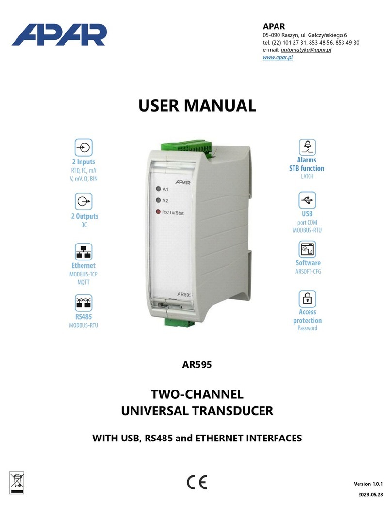
APAR AR550 User manual

TABLE OF CONTENTS
1. SAFETY RULES .............................................................................................. 3
2. INSTALLATION RECOMMENDATIONS ......................................................... 3
3. GENERAL SPECIFICATION OF TRANSDUCERS ........................................ 3
4. TECHNICAL DATA .......................................................................................... 4
5. HOUSING DIMENSIONS AND INSTALLATION SPECIFICATION ................ 5
6. DESCRIPTION OF THE TERMINAL BLOCK AND ELECTRICAL
CONNECTIONS .............................................................................................. 5
7. CONNECTORS – ARRANGEMENT AND DESCRIPTION ............................. 5
8. PROGRAMMING CONFIGURATION PARAMETERS .................................... 6
9. OUTPUT CONFIGURATION ........................................................................... 7
10. INDICATION OF MEASURING ERRORS ....................................................... 7
11. NOTES ............................................................................................................. 7
12. TRANSDUCER CONNECTION METHODS .................................................... 8
Thank you for choosing our product.
This manual will facilitate proper operation, safe use
and full utilization of this device.
Thoroughly read and understand this instruction manual before
commencing installation and start-up.
Should you have any additional questions, feel free to contact our technical advisers.
- 2 -
The manufacturer reserves the right to modify the device design and software without degrading technical parameters.

1. SAFETY RULES
n read this instruction manual thoroughly before commencing to use this device
nbefore switching on the power supply, make sure that all cables are appropriately connected to avoid
device damage
nensure suitable operating conditions in line with the device specification (supply voltage, humidity,
temperature)
nswitch off power supply before attempting any modification of connected cables
2. INSTALLATION RECOMMENDATIONS
The device has been designed to ensure a suitable level of immunity to the majority of disturbances that
can occur in an industrial environment. In environments where the level of interference is unknown it is
recommended to use the following measures preventing the potential interference of instrument operation:
n do not supply the voltage from the same lines as high power devices without using appropriate line filters
n use screened supply, sensor and signal cables, the screens should be earthed on one end only as close
to the instrument as possible
n uavoid laying supply and signal cables directly next to and in parallel to electrical power cables
and supply cables
n it is recommended to twist signal cables in pairs
n in the case of resistance sensors with 3-cable connections identical cables should be used
n avoid installing the instrument in proximity to remotely controlled devices, electromagnetic measuring
instruments, high power loads, loads with phase or group power control and other devices generating
impulse interference
n earth or neutrally ground metal bars on which bar instruments are mounted
3 . GENERAL SPECIFICATION OF TRANSDUCERS
n linear processing of the measured temperature to a current or voltage signal
n universal input :
- thermoresistance ... Pt100
- thermocouple ......... J, K, S, N, E
n analogue input proportional to the measured temperature
- current 4÷20mA or 20÷4mA (2-cable with current loop supply) or
- voltage 0÷10Vdc (3-cable)
n 581 - current output only
n housing
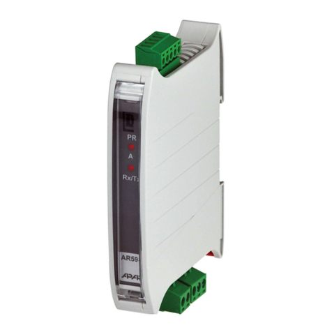
- AR580, AR581 - for installing on a TS35 bar (DIN bar)
- AR550 - industrial IP65, 94x58x35 mm
n processing range, input type and other parameters configured using the AR950 programmer
or the AR956 programming set
n exceeded processing range or sensor error signalled with a LED
n high accuracy and immunity to interference
CAUTION:
When configuring transducer parameters using the AR956 programmer, set the following transmission
parameters in ARSOFT-CFG WZ1 options:
- COM port number: specified by Windows after the AR956 driver is installed, go to “Device Manager” group
“Ports (COM & LPT)”, see “Quick start programmers AR955 and AR956”
- transmission rate (bit/s) 2400 bit/s
- MODBUS address = 1
A detailed description of configuration parameters can be found in Chapter 8 (page 6).
AR
!
!
- 3 -
!

- 4 -
4. TECHNICAL DATA
Universal input (programmed with :inP parameter) measuring range
- Pt100 (3- or 2-cable) ....................................................... -100 ÷ 850 °C
- thermocouple J ............................................................... -5 ÷ 800 °C
- thermocouple K .............................................................. -5 ÷ 1200 °C
- thermocouple S .............................................................. -5 ÷ 1600 °C
- thermocouple N .............................................................. -5 ÷ 1300 °C
- thermocouple E .............................................................. -5 ÷ 700 °C
Cold ends temperature compensation ............................ automatic or fixed
- programmed with parameters cJtY and cJtE ................ see chapter 8, Table 1
Lead resistance for Pt100 .................................................. Rd < 25 - each line with 3-cable connection
Pt100 resistance input current
Processing range (programmable) ..................................... within the input measuring range
- processing range minimum width ................................... 40°C
- measuring resolution ...................................................... 0,1 °C
Current output (programmable) ......................................... 4÷20 mA, 20÷4 mA
- load characteristics ......................................................... Robc < (Uzas-10V) / 21mA < 1238
mA
- maximum resolution ....................................................... 2mA
- nonlinearity ..................................................................... < 0,04%
Voltage output (programmable) .......................................... 0÷10 lub 10÷0 Vdc
- load characteristics ......................................................... Iobc < 4mA (Robc > 2500 )
- rmaximum resolution ....................................................... 1,25mV
- nonlinearity ...................................................................... < 0,04%
Offset and slope correction ............................................... parameters cALo (zero offset)
and cALG (sensitivity)
Processing intrinsic error (25°C)
- for Pt100 input ................................................................. < 0,2% of the full measuring range
- for thermocouple input ..................................................... < 0,3% of the full measuring range
- processing resolution error (%) ....................................... ± 0,1°C x 100 / processing range [°C]
Additional errors
- cold ends temperature compensation ............................ < 2°C (thermocouple inputs only)
- cables resistance compensation ..................................... < 0,1% Pt100 input measuring range
- environment temperature variation ................................. < 0,01 % measuring range / °C
Rated operating environment
- supply (+Vz) - transducer with current output ................. 10÷36Vdc (>10[V]+Robc[ ]x0.021[A])
- supply (+Vz) - transducer with voltage output ................ 18÷36Vdc, Iobc < 4mA
- operating temperature and relative humidity range
AR580, AR581 ....................................................... 0÷60°C, 0÷ 90%RH (no condensation)
AR550 .................................................................... -30÷60°C, 0÷100%RH (no condensation)
Response time (10÷90%) ..................................................... programmable within range 350÷1600 ms
Indication of detected errors
- optical .............................................................................. red LED
- current output signal ........................................................ 3,8 or 21 mA
- voltage output signal ....................................................... 10,6 V
Housing AR580 for TS35 bar (MODULBOX 1MH53) ............... dimensions 18x90x58 mm ~20g
Housing AR581 for TS35 bar (GUIDEBOX COMPACT) ........... dimensions ~20g
~100g
Electromagnetic compatibility (EMC)
- immunity : wg normy PN-EN 61000-6-2:2002(U)
- emissivity : wg normy PN-EN 61000-6-4:2002(U)
Factory setting .................................................................... see Chapter 8, Table 1
CAUTION - programmable parameters can be configured with the AR950 programmer or the AR956
programming set
- programming port in AR550 can be accessed after the face cover is removed
W
......................................... ~300 mA
W
- output current resolutions ............................................... 16000[ ] / (processing range [°C])
W
- output voltage resolutions ............................................... 10000[mV] / (processing range [°C])
W
, weight
- protection rating ............................................................ IP40 (housing), IP20 (terminals)
6,2x76,9x99,1 mm, weight
- protection rating ............................................................ IP40 (housing), IP20 (terminals)
Housing AR550 (industrial) ................................................ dimensions 94x58x35mm, weight
- protection rating ............................................................ IP65

- 5 -
5. HOUSING DIMENSIONS AND INSTALLATION SPECIFICATION
AR580, AR581
AR580 - MODULBOX 1MH53 ........... 18x90x58 mm
AR581 - GUIDEBOX COMPACT .......
Installation on bar ............................ TS35 (DIN EN 50022-35)
Connecting loads and supply ........ screw terminals
AR550 (figure in Chapter 7)
Dimensions ...................................... 94x58x35mm
6,2x76,9x99,1 mm
Material ............................................. policarbonate, IP65
Mounting holes ................................ 2 holes Φ9mm
or 2 clamps <5mm,
span 80mm
58
90
7. CONNECTORS – ARRANGEMENT AND DESCRIPTION
!
CAUTION :
Connecting devices other than AR950 or AR956
programmer can cause permanent damage
to the connected device and to the transducers
programming
ports
LEDs
AR580
6 5 4
1 2 3
AR580
3
2
1
4
5
AR581
AR580
AR581
6. DESCRIPTION OF THE TERMINAL BLOCK AND ELECTRICAL CONNECTIONS
terminals descriptions
1-2-3 Pt100 input, 2- or 3-wire
2-3 termocouple input TC (J, K, S, N, E)
4 supply input +Vz
5 4÷20mA current or 0÷10Vdc voltage output
6 voltage output ground
6
5
+Vz
OUT
4
GND
1
2
3
+
-
TC
Pt100
(2-w)
(3-w)
IN
OUT
AR581 - current output only
AR550
inside with face cover removed
3 cable model
INPUT
SUPPLY
OUTPUT
programming
port
5 8
3
2
1
6
5
4
+
-
+Vz
OUT
GND
dioda LED
Φ9
80
94
64

8. PROGRAMMING CONFIGURATION PARAMETERS
All the configuration parameters of the device are stored in the non-volatile internal memory.
When the device is switched on for the first time, an error may occur due to the lack of a sensor or the fact
that the sensor that is connected is not one that is factory-programmed. In such a situation, the appropriate
sensor or analog signal should be connected or the parameter configuration must be performed.
Methods of parameter configuration via the PR socket (accessible by opening the transparent front cover):
1. Use the AR956 programmer and the ARSOFT-CFG software to:
-connect the device to a computer port and to start and configure the ARSOFT-CFG application
-after the connection has been established, the current measured value is displayed in the window
of the software
-setting and viewing of the device parameters is possible in the parameter configuration window
-new parameter values must be approved with the Approve changes button
-the current configuration can be saved in a file or set using values read from a file
NOTE:
-before disconnecting the device from a computer, press the Disconnect device button (ARSOFT-CFG)
-in the event of no response:
-in the Program options check the configuration of the port and the MODBUS address of the device
(transmission speed 2,400 bit/s, MODBUS address=1)
-make sure that the serial port drivers in the computer have been properly installed for the AR956
programmer
-disconnect for a few seconds and then reconnect the AR956 programmer
-restart the computer
- if the AR955 programmer is used instead of the AR956 programmer, connect the power supply voltage
to the transducer (put it in the current loop)
2. Use the autonomous AR950 programmer to:
-connect the power supply voltage to the transducer;
-use the cable included in the set to connect the AR950 programmer to the device being configured
(an AR5xx series transducer);
-the programmer can be connected both before the power supply is switched on and during operation
of the device;
-enter the configuration parameters programming mode by pressing (for about 2 s) the CONF button until
the ConF message briefly appears on the display and then the mnemonic name of the first parameter
is displayed ( inP ); by pressing the button, you can move to the next parameter, and by pressing
the button - to the previous parameter ( :inP FiLt :dot …); a list of configuration parameters
can be found in the user instruction of the device being configured;
-in order to change or view the value of the current parameter, press SET (edition of the parameter);
-by using or , you can change the value of the current parameter;
-by pressing SET again, you can save the edited value and return to the parameter name display
(e.g. FiLt );
-in the parameter edition mode, by pressing ESC for a short time, you can cancel the changes and return
to the parameter name display mode;
-you can exit the configuration parameters programming mode by pressing the ESC button for a long time
(approx. 1 s); otherwise, the mode is switched off after approx. 2 minutes;
-in the normal mode, the measured value is displayed;
Detailed information can be found in the user instruction of the AR950 programmer.
In the event of indications different than the actual value of the input signal, the zero and the sensitivity of
a sensor can be tuned: parameters 7: cALo (zero offset) and 8: cALG (sensitivity).
In order to restore the default settings, use the file with the default configuration in ARSOFT-CFG software.
- 6 -
!

11. NOTES
10. INDICATION OF MEASURING ERRORS
The transducer detects the following measuring errors:
- low or high processing range exceeded
- connected sensor differs from the one set in configuration parameters
- sensor circuit damaged
Indication of measuring errors:
- LED flashes
- 7 -
9. OUTPUT CONFIGURATION
Input signal is directly proportional to the measured signal within the range set with parameters 5: rbot
and 6: rtoP. Figures below present the principle of operation of the analogue output.
Remarks: (1) - dla FiLt=2 response time is about 0,35s, for FiLt=15 about 1,6s. A higher filtering level
corresponds to a smoother measurement value and longer response time
(2) - this applies to displaying data on the AR950 programmer
Reverse characteristics can be obtained by setting rbot > rtop
for AR553: rbot = -30.0, rtop = 60.0
0 :inPinput type RTD 0 = Pt100 0 =
(sensor) Thermocouples 1 = J, 2= K, 3 = S, 4= E, 5 = N Pt100
1 FiLtfiltration level (1) 2 ÷ 15 8 = 0,9s
2 :dotindication resolution (2) 0 = 1°C, 1 = 0,1°C 1 =0,1°C
3 cJtYcold end temperature 0 = automatic, 0
compensation type 1 = fixed, value in acc. with parameter 4 cJtE
4 cJtEcold ends temperature 0.0 ÷ 50.0 °C (for thermocouples for cJtY=1) 25.0 °C
5 rbottemperature for 4mA/0V in the measuring range of input type 0.0°C
6 rtoptemperature for 20mA/10V in the measuring range of input type 100.0°C
7 cALozero offset /00.0 ÷ 100.0 °C or /000 ÷ 1000 units (1) 0.0°C
8 cALGamplification -85.0 ÷ 115.0 % 100.0%
Table 1. Configuration parameters
No Name Parameter description Parameter value and change range factory user
Settings
21mA
output 4 20mA÷
20mA
4mA
3,8mA
rbot rtoP
measured value
output 20 mA÷4
21mA
20mA
4mA
3,8mA
rtoP rbot
measured value
direct characteristic : rbot < rtoP reverse characteristic : rbot > rtoP

- 8 -
- Pt100 temperature sensor connected to terminals 1, 2 and 3, thermocouples to terminals 2 and 3
- supply cable to terminal +Vs (4)
- instrument current or voltage input cable to terminal OUT (5)
12.1. Connecting the sensor, power supply and output of a 2-cable transducer
(transducer supplied from the instrument)
2-cable
transducer
4÷20mA
supply
meter
or
controller
Supply output +24V
Current input 1
3
2
5
4
OUT
+Vz
sensor
3-cable
transducer
supply
meter
or
controller
Supply output +24V
Current or voltage input 1
3
2
5
4
OUT
+Vz
sensor
Supply ground 6
GND
- Pt100 temperature sensor connected to terminals 1, 2 and 3, thermocouples to terminals 2 and 3
- supply cable to terminal +Vs (4)
- instrument measuring ground cable to terminal GND (6)
- instrument current or voltage input cable to terminal OUT (5)
12.3. Connecting the sensor, power supply and output of a 3-cable transducer
(transducer supplied from the instrument)
- Pt100 temperature sensor connected to terminals 1, 2 and 3, thermocouples to terminals 2 and 3
- power supply cable +24V to terminal +Vs (4)
- power supply cable -24V to instrument measuring ground
- instrument current or voltage output cable to terminal OUT (5)
12.2. Connecting the sensor, power supply and output of a 2-cable transducer
(with an external power supply)
2-cable
transducer
4÷20mA
supply
meter
or
controller
Current input 1
3
2
5
4
OUT
+Vz
sensor
- 24V +
External power
supply 24Vdc
Measuring ground
- Pt100 temperature sensor connected to terminals 1, 2 and 3, thermocouples to terminals 2 and 3
- power supply cable +24V to terminal +Vs (4)
- power supply cable -24V to terminal GND (6), then to instrument ground
- instrument current or voltage input cable to terminal OUT (5)
12.4. Connecting the sensor, power supply and output of a 3-cable transducer
(with an external power supply)
- 24V +
External power
supply 24Vdc
3-cable
transducer
supply
meter
or
controller
Current or voltage input 1
3
2
5
4
OUT
+Vz
sensor
Measuring ground 6
GND
12. TRANSDUCER CONNECTION METHODS
This manual suits for next models
2
Table of contents
Other APAR Transducer manuals
Popular Transducer manuals by other brands

Magpowr
Magpowr IP-80 instruction manual

Camille Bauer
Camille Bauer Gossen MetraWatt SINEAX DME 401 operating instructions

Balluff
Balluff BTL7-A501 Series Condensed guide

Mianyang Weibo Electronic
Mianyang Weibo Electronic WBV342U05-S user manual

Panametrics
Panametrics C-ET installation guide

LEM
LEM DK series installation guide