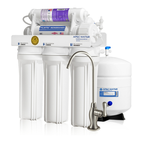
Apec Water Hydro Express Water Softener 30 Service manual

INSTALLATION INSTRUCTION
& OWNER’S MANUAL
All Rights Reserved © APEC Water Systems
www.FreeDrinkingWater.com
SOFTENER SERIES


Thank you for choosing APEC Water Softener.
Please read and become familiar with instructions and parts needed before proceeding with the
installation.
1. Use a licensed plumber to install this product.
2. Check with your state and local Public Works Department for plumbing and sanitation codes.
You must follow these guidelines as you install the water softener.
3. Inspect the system: Please take the system and all the components out of the box. Inspect the system
and all the connection fittings carefully, making sure nothing is damaged during shipping. If any part is
cracked or broken, please do not proceed with the installation and contact APEC or your distributor for an
exchange or diagnosis.
4. Review the following installation requirements.
1). Water Temperature Parameter: The system MUST NOT be installed in an area where it is exposed to
direct sunlight and must be protected against freezing and extreme heat.
• Maximum: 100° F (37.8° C)
• Minimum: 32° F (0° C)
2). Water Pressure Parameter: The maximum allowable inlet water pressure is 90 psi. If daytime pressure
is over 80 psi, night time pressure may exceed the maximum allowed water pressure. Use a pressure
reducing valve (PRV) to reduce the pressure if needed.
• Maximum: 90 PSI
• Minimum: 25 PSI
Please keep this Owner’s Manual for future reference.
It contains useful information on how to maintain and care for your
APEC Water Softener
WARNING:
For your safety, the information in this manual must be followed to minimize the risk of electric shock, prop-
erty damage or personal injury. Manufacturer warranty can be voided if the installation requirements are not
met.

3). Chlorine & Chloramine Tolerance: Softener resin may degrade in the presence of chlorine or chlo-
ramines. Feedwater that contains these contaminants will reduce the life of the resin. In these condi-
tions, a whole house carbon filtration system with chlorine, chloramine reducing media is recom-
mended.
• Maximum: 2 ppm
4). Pre-install environment checklist:
a. Not for use with microbiologically unsafe water. Pre-filtration to remove contaminants and heavy
sediment is recommended to ensure optimum performance and product life.
b. Properly ground to conform with all governing codes and ordinances. Use only lead-freesolder and
flux for all sweat-solder connections as required by state and federal codes.
c. Place the softener as close as possible to the pressure tank (well system) / water meter (city water).
d. Place the softener as close as possible to a floor drain, or other acceptable drain point (laundry
tub, sump, standpipe, etc.) to prevent air breaks and back flow.
e. Place softener in a place where water damage is least likely to occur if a leak develops.
f. The brine tank should be located no more than 10 feet from the resin tank.
g. Connect the softener to the main water supply before the water heater. Do not run hot water
through the softener. The maximum temperature of softener water is 100º F.
h. Outside faucets and irrigation systems should be supplied with pre-softened water. If this is not pos
sible, be sure to bypass the softener when watering grass or plants. Chronic soft water exposure can
be detrimental to plant life.
i. An electric outlet must be within 6 feet of the softener. The transformer has an included
8 feet power cable. Be sure the electric outlet and transformer are protected from water and wet
weather.
j. If installing outside, necessary steps must be taken to ensure the softener, installation plumbing, wir
ing, etc. are protected from the elements and contamination sources.
k. Handle with care when moving the water softening system. Do not drop, drag, or set on areas with
sharp protrusions.
l. The system works on a standard 120v power plug only. Do not use any other transformer except the
one that is included with the system.
m. The transformer must be plugged into an indoor, grounded outlet.

n. Use only clean water softening salt with at least 99.5% purity. Extra course grade or crystal salt is
recommended. Do not use rock, block or granulated salts. These contain contaminants that could
cause problems during maintenance.
o. Always keep the salt lid in place on the softener unless servicing or refilling the unit.
p. Some applications may not have a level surface to place the tank. The floating base allowsthe tank
to be leveled within the base and ensure proper operation.

TABLE OF CONTENTS
1
01 Parts List ...................................................................................... page 2
02 Installation Overview ................................................................... page 5
03 Salt Tank Preparation .................................................................. page 7
04 Connect the Softener .................................................................... page 10
05 Digital Control Valve Installation .................................................. page 11
06 Bypass Operation ........................................................................ page 14
07 Digital Control Valve Display ....................................................... page 15
08 Manual Regeneration ................................................................. page 18
09 Technical Specifications ................................................................ page 18
10 Limited Product Warranty ............................................................. page 19

PARTS LIST
2
Bypass Valve (With By-
pass Valve Connector X2)
X 1
Digital Control Valve
X 1
Bypass Valve Connector
X 2
Digital Control
Valve Transformer
X 1
Softener Tank
X 1
Parts List for APEC Water Softener Installation Kit (2 packages):
Package #1: Softener tank.
Package #2:
Digital control valve and installation kit.
Bypass Valve Locking Clip
X 4
Salt Tubing Connector
and Adapter
X 2 Sets

3
Tank Grille
X 1
Overflow Adapter
with Lock Nut
X 1
Salt Tank
X 1
Bypass Valve Connector
O-ring (Black color)
X 2
Brine Line Flow
Controller (Red color)
X 1
Digital Control Valve
O-ring (Black color)
X 1
Drain Connector O-
ring (Black color)
X 1
Drain Connector
X 1
Salt tank and installation kit.

4
Salt Well Clamp
X 1
Tank Cup
X 4
Salt Well
X 1
Salt Well Lid
X 1
Tank Tube Adapter
Lock Nut
X 1
Salt Tank Tubing
X 1

5
INSTALLATION OVERVIEW
Top view
Brine tank installation
Side view
In
Out

6
Required Tool List for System Installation
• Channel Locks
• Screwdriver
• Plumber’s Tape
• Utility Knife
• Two Adjustable Wrenches
• Please note the modification to home plumbing may require the use of additional tools.
Required Components not Included with the System
• 80 lbs Extra Course Grade Salt Pellets are needed to fill the brine tank. The softener system will use any
kind of salt formulated for water softener use, but it is advised to use the pellet-shaped salt as it tends to
dissolve more evenly. (Potassium can be used for a salt-free alternative)
SITE REQUIREMENTS:
• Water pressure: 25-90 psi.
• Water temperature: 40° F - 100° F.
• The tanks should be on a firm, level surface.
• Electrical: Use a 100-240v, 60Hz uninterrupted outlet.
• Use 1” (or 3/4” depending on system) copper, brass, or PEX pipe and fittings. Some plumbing codes may
also allow PVC plastic pipe.
• Current draw is 0.25 amperes.

7
SALT TANK PREPARATION
1. Install 4 tank cups to the tank grille.
2. Install the tank grille on the bottom of the salt tank.
3. Install the salt well into the tank grille.
Preparing salt tank for installation. Please follow the steps below:

8
4. Install salt well clamp on the salt well. Put the tank tube adapter lock nut on the outside of the tank.
5. Unscrew to remove the salt tubing connector and adapter from the salt well, insert the salt tubing through
the salt well clamp.
6. Install salt tubing connector and adapter to the salt tank tubing. Screw and connect the salt tubing con-
nector back to the salt well with tubing.

9
IMPORTANT! This optional brine tank overfill connection step is not required. It’s for addi-
tional security against leaks and prevention of disrupted service purposes only.
Optional Brine Tank Overfill Connection:
Below the brine hose connection you will notice a 90-degree barbed connection facing downward. This
connection is optional since the brine well is equipped with an automatic float valve shutoff.
If you still want to utilize the overfill connection, lubricate the barbed connection with silicone grease or any
food-grade oil. You will need to purchase an additional ½” plumbing hose and place the hose onto the
connection for a secure seal. Typically, the other end of the hose will feed off into a floor drain, laundry style
sink, or dedicated drain connection.
Note:
Make sure the brine line is secure to the connection provided on the brine tank. If the brine
line is not secure and sealed, it may not be able to perform a proper system regeneration
when needed, and can potentially cause overfill in the brine tank and result in leaks.
7. Install overflow adapter to the salt tank and close with the well lid.

10
CONNECTING THE SOFTENER
IMPORTANT: Please review before installation.
1. On copper plumbing systems, be sure to install a grounding wire between the inlet and outlet piping to
maintain grounding.
2. Make sure the brine line is secure to the connection provided on the brine tank. If the brine line is not se-
cure and sealed, it may not be able to perform a proper system regeneration when needed, and can poten-
tially cause overfill in the brine tank and result in leaks.
3. A direct connection into a waste drain is not recommended. A physical air gap of at least 1.5” should be
used to avoid bacteria and wastewater traveling back through the drain line into the softener.
4. Any solder joints being soldered near the valve must be done before connecting any piping to the valve.
Always leave at least 6” (152 mm) between the control valve and joints being soldered when soldering pipes
that are connected to the valve. Failure to do this could cause damage to the valve.

11
1. Unscrew tank cap from the top of the tank and remove tube cover.
DIGITAL CONTROL VALVE INSTALLATION
Assembled view with bypass valve
Bypass installation parts diagram

12
4. Detach both bypass valve connectors from bypass valve and verify the flow sensor is properly in place
then install both bypass valve connector o-ring.
5. Screw the bypass valve connectors to the digital control valve.
6. Push the bypass valve into the bypass connectors securely to install the bypass locking clips.
2. Obtain the digital control valve and install the digital control valve o-ring on the bottom of digital control
valve.
3. Screw the digital control valve tightly onto the top of the tank.
Flow sensor preinstalled

13
8. Plug the digital control valve into an electrical outlet and connect the leak detector to the bypass valve to
complete this installation then proceed with pipe connections.
7. For the brine tank connection, please obtain a small screw driver or pen and place the brine line flow
controller (red color) on the tip with the cone side facing toward the brine line connection then properly
install the salt tank tubing.
Leak Detector
Leak detector connection

14
BYPASS OPERATION
To shut off water to the system, please position arrow handle as shown in the bypass operation diagram to
the right. If your valve doesn’t look like the diagram, contact your service technician for instructions on how
to shut off water.
Water turned on Water turned off
(Bypassed)

15
DIGITAL CONTROL VALVE DISPLAY
Lock Symbol (top left corner) Light is on indicates the timer buttons are locked. To unlock, press and hold
both and button for 5 seconds until Lock symbol light is off you will hear a “DI” sound.
UpDownManual/Return
Menu/Confirm
Display Screen
Button Area
Water
Cur. F. R. : 0. 00 gpm
11 : 16 : 39
In-Service
Water System
Water
Cur. F. R. : 0. 00 gpm
11 : 16 : 39
In-Service
Water System
Recommended:
Remove The plastic screen protector after installation.
This manual suits for next models
3
Table of contents
Other Apec Water Water Dispenser manuals
Popular Water Dispenser manuals by other brands

WaterLogic
WaterLogic CUBE manual

Thermo Concepts
Thermo Concepts Celsius instruction manual

Omnifilter
Omnifilter BF35 installation instructions

Halsey Taylor
Halsey Taylor WM8 Series owner's manual

WaterLogic
WaterLogic WL400 Series Installation procedures

SpectraPure
SpectraPure MAXCAP RO/DI Installation and operating manual

Huawei
Huawei NetCol5000-C030 Series quick guide

MARLO
MARLO MR Series Installation, operation and maintenance manual

First Sales
First Sales NC Series Installation instructions and owner's manual

Elkay
Elkay EFY8 1A Series Installation, care & use manual

UNIPRODO
UNIPRODO UNI WATER 03 user manual

Elkay
Elkay EZSTL8S2JOC Installation & use manual