Superior Water 32-2010 User manual

1
MODEL 32-2010 & 48-2010
OWNER’S MANUAL
Congratulations on having purchased a quality and well built Superior Water Softener. On a
normal installation, your water softener should be connected to all of your plumbing with the
exceptions of your kitchen cold side and your outside faucets. The plumbing connection is
made by using three valves that are generally located directly above the water softener. These
three valves constitute the bypass, which look like the letter “H” when looking at it. In the event
that you should have to shut the water off to the water softener due to a leak, continue with the
following instructions.
TO SHUT THE WATER OFF ON THE SOFTENER
1.) Directly above the water softener are three valves. Turn the left and right valves
in a clockwise direction until they are completely closed.
2.) Turn the middle valve open by turning it counter clockwise. The water should
now be turned off on the water softener and you should have water to your house.
THE SALT AND WATER LEVEL INSIDE THE SALT TANK
It is recommended that the salt level not fall more than 3"(inches) below the water level inside
the salt tank. The water level inside a round salt tank is generally one to one-half feet deep. The
square salt tanks are generally about half to two-thirds full of water. Should the softener run out
of salt or you allow the salt level to drop down too far, you may experience hard and/or salty
water. To avoid this, we recommend keeping the salt tank full of salt or at least keeping the salt
level above the water level at all times. Should you experience salty water coming through your
plumbing, the quickest way to flush it out is running the cold water inside your bathtub until the
salt is all flushed out.
Your water softener will function with any type of salt; however our experience has shown us
that fewer problems will occur when using salt pellets. Salt pellets are cleaner, rarely have any
debris and they do not have a tendency to form salt bridges as does rock salt. Also rock salt has
a tendency to carry more dirt and debris with it, which in turns make your salt tank appear very
dirty inside and at times cause it to have a foul odor. However, this dirt will not harm the water
softener.
OPERATING THE WATER SOFTENER
GENERAL INFORMATION
The control valve is designed to initiate regeneration according to the installer’s customized
parameters. Following the instructions contained in this section will allow the homeowner to
change the time of day, initiate the Holiday Mode program or to initiate a Delayed Regeneration.
These instructions are also found on the front of the control valve, behind the flip down cover.
The control valve utilizes a super capacitor to maintain time for minimum of 2 hours in the event
of a power loss. Should the power be out longer than 2 hours, it may be necessary to reset the
unit to the correct time of day.

2
NOTE: The control valve is an electronic item and therefore is sensitive to power surges just
like any other electronic item. For this reason, it is recommended that you have a surge
protector installed for the water softener.
PROGRAMMING THE TIME OF DAY
Pressing the scroll button enters the Time of Day programming mode. Once pressed the time of
day will start flashing. To adjust the time, press the up arrow or down arrow
IMMEDIATE REGENERATION
When the control valve is in service, the user requests an immediate regeneration by pushing the
scroll buttons three times. “REGENERATION IN 10 SEC “ message will show. The
regeneration will occur when the second counter reaches zero
HOLIDAY MODE
Regeneration is not allowed when the control valve is in the Holiday Mode. The word Holiday will
blink when scrolled to on the control board. After sixty seconds, the unit enters the Holiday Mode.
The only way the unit comes out of Holiday Mode is a flow rate greater that 1.5 gallons per minute or
if an immediate regeneration is started. Scrolling out of Holiday Mode is the last way to exit. After
exiting, the unit will go into an immediate regeneration.
DELAYED REGENERATION
While in service mode, the user requests a delayed regeneration by scrolling to the
“REGENERATION AT 02:00 “ message, by pushing the scroll button four times. Leave the
setting in this mode in order to initiate a delayed regeneration. Regeneration will occur when the
time clock reaches the delayed regeneration time. After the regeneration takes place, the clock will
return to the time of day.
NOTE: If at any time you have experienced hard water due to a malfunction of the equipment or
having ran low or out of salt, the water softener will need to be manually regenerated three nights in-
a-row or three times in-a-row with a minimum of two hours in between each manual regeneration.
To start a manual regeneration, follow the instructions for IMMEDIATE REGENERATION.

3

4
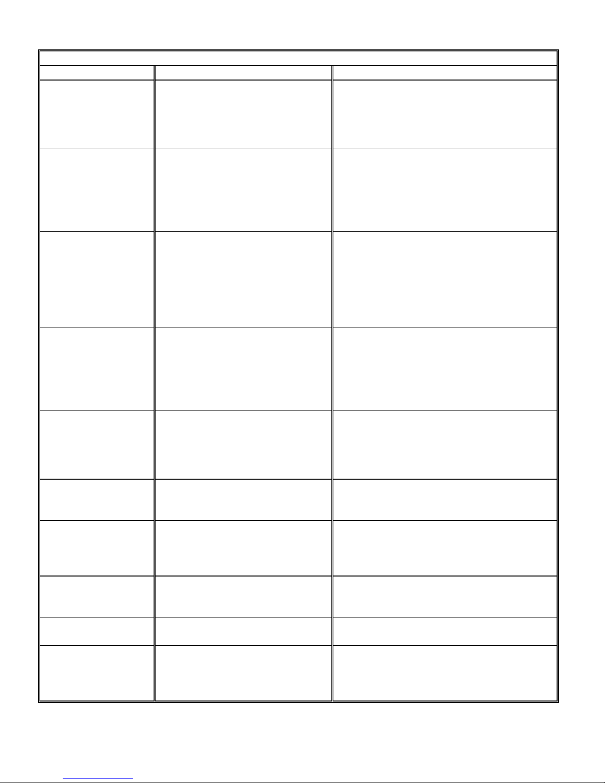
TROUBLE SHOOTING GUIDE
PROBLEM POSSIBLE CAUSE CORRECTION
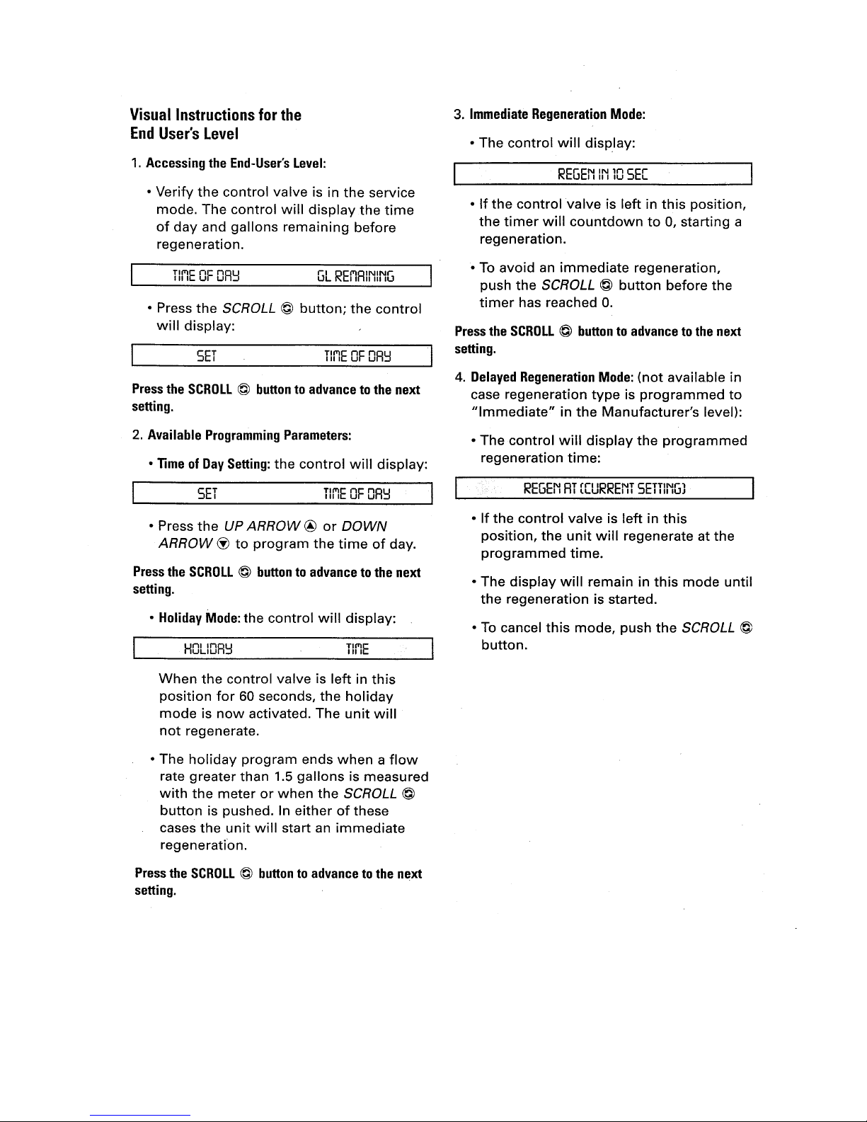
Softener will not
regenerate.
A. Bad electrical connection.
B. Broken motor
C. Broken or stripped gears.
D. Gallon counter not counting
A. Check electrical connection.
B. Replace motor.
C. Replace gears.
D. Remove debris or replace part. (Located
on outlet port of control valve)
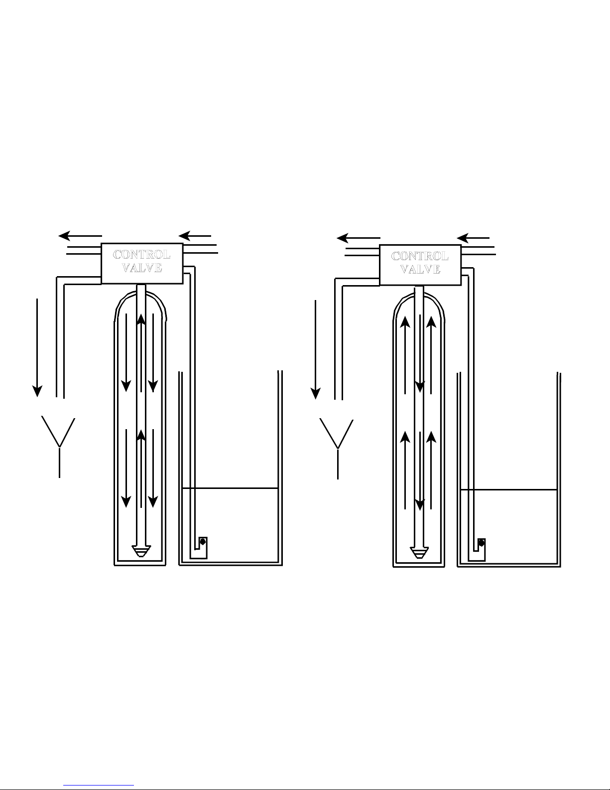
Drain opens but water
does not leave salt
tank.
A. Low inlet water pressure.
B. Broken or torn diaphragm.
C. Retaining ring missing.
D. Foreign material on stem or
internal seats.
E. Drain line kinked or restricted.
A. Increase inlet water pressure.
B. Replace diaphragm.
C. Add retaining ring.
D. Clean stem and seat on main
body.
E. Straighten or un restrict drain line.
Softener does not
draw brine.
A. Plugged injector screen.
B. Plugged or worn injector.
C. Inadequate backwash.
D. Low inlet water pressure.
E. Broken or plugged brine float
F. Kinked or restricted drain line.
A. Clean or replace.
B. Clean or replace.
C. Adjust backwash flow rate with
backwash adjuster.
D. Increase water pressure.
E. Clean or replace.
F. Straighten or unrestraint drain line.
Low or inadequate
capacity after
regeneration.
A. Plugged injector.
B. Plugged injector screen.
C. Increase in water consumption.
D. Insufficient quantity of brine.
E. Ran out of salt at one time.
F. Leaking toilets or faucets.
A. Clean or replace.
B. Clean or replace.
C. Increase frequency of regeneration.
D. Raise float level on brine valve.
E. Regenerate softener 3 nights in-a-row.
F. Repair leak.
Water chatter at unit
during regeneration
A. High backwash rate.
B. Low water pressure.
C. Diaphragm spring not properly
located on stem.
D. Restricted drain line.
A. Adjust backwash flow adjuster
B. Increase water pressure.
C. Locate spring on tip of stem assembly.
D. Straighten or un restrict drain line.
Water flows to drain
when not regenerating.
A. Foreign matter trapped in drain
valve.
B. Drain paddle out of adjustment.
A. Attempt to flush out by putting unit into
regeneration.
B. Replace drain paddle.
Salt in lines after
regeneration.
A. Rinse rate to low.
B. Excessive brine in salt tank.
C. Insufficient rinse time.
A. Change to larger injector disk.
B. Lower float setting or check for leak on
float.
C. Increase length of regeneration cycle.
Valve leaking between
body and head
assembly or back cap.
A. Torn diaphragm or pinched
outlet gasket.
A. Replace items.
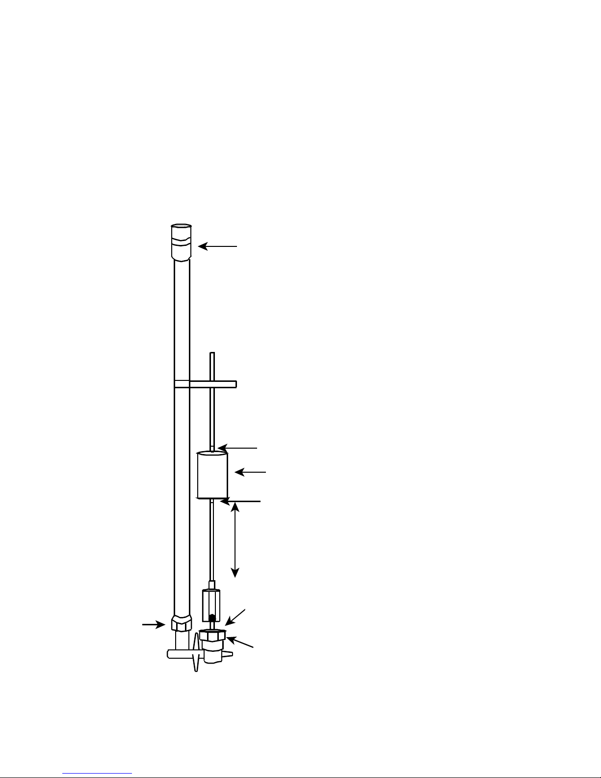
Too much water brine
tank
A. Foreign matter in brine float.
B. Loose brine float fittings.
A. Clean or replace brine float.
B. Tighten or replace brine float fittings.
No water in brine tank A. Brine float set to low A. Adjust brine float to allow 1 ft. to 1½ ft.
of water into Round and 15x15 Square salt
tanks only. On 11x11 Square salt tanks, set
float to approximately fill tank half full.

5
Brine Level
DRAIN
Brine Level
DRAIN
BACKWASH
The backwash cycle position directs water
to flow down through the distributor tube
and up throught the filter media and to
drain. Foreigh material and media fines are
flushed from the mineral tank during this
cycle to prepare the media for filtering.
OUTLET INLET OUTLET INLET
SERVICE
WATER FLOW
The service cycle position directs
untreated water to flow down through
the filter media in the mineral tank and
up through the distributor tube. The
water is conditioned when passing
through the media.

6
BRINE FLOAT
6" to 8"
Water enters and
leaves from here
Used to adjust
water level
Can be unscrewed
to remove debris
from inside
A.
B.
C.
Fitting
D. John Guest fitting
E. Rubber gromet
F. Rubber gromet
A. Used to adjust water level. In round salt tanks, and 15x15 square salt tanks the water level
should be anywhere from 1 ft. to 1½ ft. In 11x11 square tanks, the tank should be ½ to 2/3
full of water.
B. Unscrewing this nut allows you enter the chamber where debris can be easily removed
C. Compression fitting.
D. John Guest fitting.
E & F. Rubber gromets that hold float ball in place on the fiberglass rod.

7

8

9
This manual suits for next models
3
Table of contents
Other Superior Water Water Dispenser manuals
Popular Water Dispenser manuals by other brands

EcoWater
EcoWater Comfort Series instructions

Hill
Hill 3900 Service manual

Acqua Brevetti
Acqua Brevetti MiniDUE Installation and operating manual

Grunbeck
Grunbeck GENO-mat duo WE-X 65 Operation manual

Follett
Follett 25CI425A/W Installation, operation and service manual

Elkay
Elkay EFA4 1D Series Installation, care & use manual

Elkay
Elkay LZO Series Installation & use manual

First Sales
First Sales FSN10 Installation instructions and owner's manual

Kolin
Kolin KWD-BLC-2088B owner's manual

Elkay
Elkay VRCGRN8 Series Installation & use manual

Connect
Connect 23 A RI Installation, use and maintenance handbook

Sharp
Sharp SWD-78EHL-SL Service manual