Apeks 1500-5L User manual

1500-5L AND 1500-20L
BOTANICAL OIL EXTRACTION SYSTEM
OWNER’S MANUAL
WARNING
FAILURE TO FOLLOW THE SETUP AND OPERATION PROCEDURE
PROVIDED IN WITHIN THIS MANUAL MAY VOID THE EXTRACTION
SYSTEM’S WARRANTY
Apeks LLC
150 Commerce Blvd.
Johnstown OH 43031
614-809-1160
www.apekssupercritical.com

Updated 8/8/2018 Copyright Apeks LLC, 2014
2
Table of Contents
1. Critical Safety Overview.........................................................................................................3
2. Unpacking Instructions...........................................................................................................4
2.1. Shipping Crate Inspection................................................................................................4
2.2. Unpacking Instructions....................................................................................................5
3. System Requirements............................................................................................................7
3.1. General System Specifications........................................................................................7
3.2. Facility .............................................................................................................................7
3.3. Electrical..........................................................................................................................7
3.4. Recirculating Water Chiller/Heater ..................................................................................8
4. Setup and Assembly..............................................................................................................8
4.1. Leveling Feet...................................................................................................................8
4.2. Coolant Connections.......................................................................................................8
4.3. CO2Connections...........................................................................................................10
4.4. Air System Connections ................................................................................................11
4.5. Electrical Connections...................................................................................................11
4.6. Chiller/Heater Setup......................................................................................................12
5. System Operation ................................................................................................................13
5.1. 1500-5L and 20L Overview............................................................................................13
5.2. Automation Systems Overview......................................................................................14
5.3. Pre-Cleaning..................................................................................................................15
5.4. Opening Extraction Vessel ............................................................................................15
5.5. Loading Botanical or Other Media.................................................................................16
5.6. Closing Extraction Vessel..............................................................................................16
5.7. Chiller Start Up..............................................................................................................17
5.8. Evacuating the System..................................................................................................17
5.9. Conducting an Extraction...............................................................................................18
5.10. Removing Spent Botanical ............................................................................................19
5.11. Oil Collection .................................................................................................................19
6. Troubleshooting ...................................................................................................................22
6.1. Ice On Separator...........................................................................................................22
6.2. Opened Bottle Too Early...............................................................................................22
6.3. Low Extractor Pressure.................................................................................................22
6.4. Extractor Overpressure – Orifice Clog...........................................................................22
6.5. Low Separator Pressure – Orifice Clog.........................................................................23
6.6. Low Separator Pressure – Wrong Orifice Size..............................................................23
6.7. High Separator #1 Pressure (>350-psi) and Low Separator #2 Pressure......................25
7. System Maintenance............................................................................................................27
8. Replacement and Spare Parts List.......................................................................................29
Appendix A. 1500-5L and 20L Automated System Screen Shots...............................................30
Appendix B. 1500-5L and 1500-20L Piping and Instrumentation Diagram.................................34
Appendix C. CO2Phase Diagram...............................................................................................36
Appendix D. Pre-Training Checklist............................................................................................37
Updated 8/8/2018 Copyright Apeks LLC, 2014
3
1. Critical Safety Overview
Throughout these instructions, this symbol is used to indicate that the
instructions are critically important to your safety and the safety of your system.
Failure to follow the instructions as written can result in a rapid release of high
pressure CO2potentially causing equipment or personnel damage.
WARNING
Subcritical and Supercritical CO2systems operate under high pressure. Operators must be fully
trained and familiar with the system. Failure to operate the system can result in equipment
damage and/or bodily injury.
WARNING
Subcritical and Supercritical CO2systems use large amounts of CO2during operation. Ensure
that system is installed in a well-ventilated area to prevent buildup of CO2 which can cause
asphyxiation. Use of a CO2monitor is strongly recommended.
WARNING
Opening a vessel under pressure can result in a rapid release of pressure and ejection of the
material inside the vessel. DO NOT ATTEMPT TO OPEN A VESSEL UNDER PRESSURE!
Always make sure a vent path for the vessel is opened and the corresponding pressure gage
reads zero prior to loosening the vessel closure bolts.
WARNING
Subcritical and Supercritical CO2systems are designed to operate in doors. Extreme
temperatures (below 50°F and above 85°F) will negatively impact the functionality of the system.
The environmental temperature range is for the system, chiller, pump and CO2bottles.
WARNING
Only use Propylene Glycol and distilled water in the chiller and cooling system. Never use
Deionized Water in the chiller or cooling system.
WARNING
Never turn on the chiller without the thermocouple probe installed and connected to the chiller.

Updated 8/8/2018 Copyright Apeks LLC, 2014
4
2. Unpacking Instructions
Apeks 1500-5L and 1500-20L systems are shipped in three separator crates. One containing
the chiller, one containing the air compressor and one containing the botanical extraction
system. Following are the steps for removing the system from the crates and making service
connections for initial use.
2.1. Shipping Crate Inspection
2.1.1. Prior to opening the crate(s), verify that that there was no external damage caused
to the wood crate. If damage is found, do not accept the delivery from the
shipping company without first opening the crate to verify that there was no
damage to the system. Additionally, call Apeks at 614-354-4451 to report damage
and start the reporting process with the shipping company.
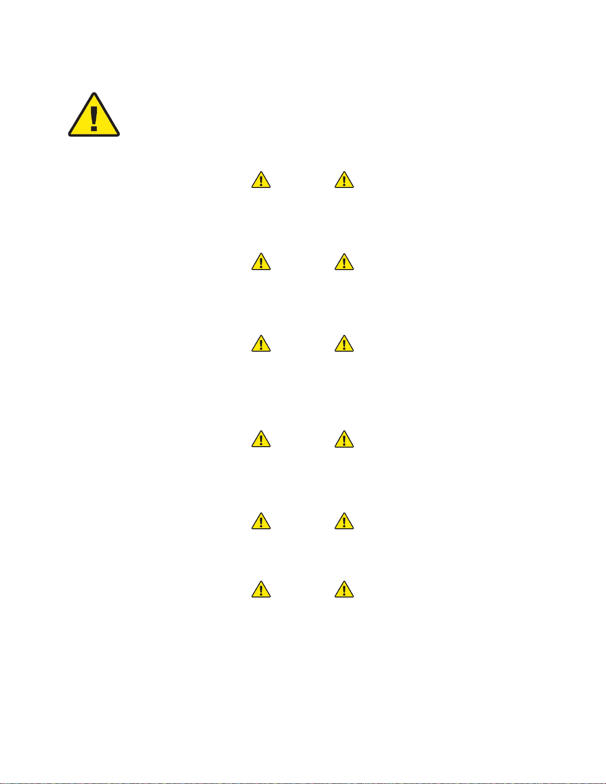
Figure 1. Approximate appearance of 1500-5L and 1500-20L Shipping Crate
2.1.2. Locate the two TiltWatch Plus sensors on the outside of the crate. Ensure that the
crate has not exceeded 30° in any direction. If the crate has exceeded 30°, do not
accept the delivery from the shipping company until contacting Apeks at 614-354-
4451.
Figure 2. TiltWatch Sensor
Updated 8/8/2018 Copyright Apeks LLC, 2014
5
2.2. Unpacking Instructions
2.2.1. Remove the plywood from the all four sides and the top of the crate using a
Phillips head screwdriver.
Figure 3. Appearance of crate with top removed
2.2.2. Remove the support hardware inside the crate. Support hardware should include
a cordless impact wrench, impact wrench socket, 11/16-in open end wrench, 5/8-
in ratchet wrench, aluminum funnel, two O-rings, four sanitary gaskets, a flexible
metal hose, a vacuum hose, vacuum pump and four rubber coated leveling feet.
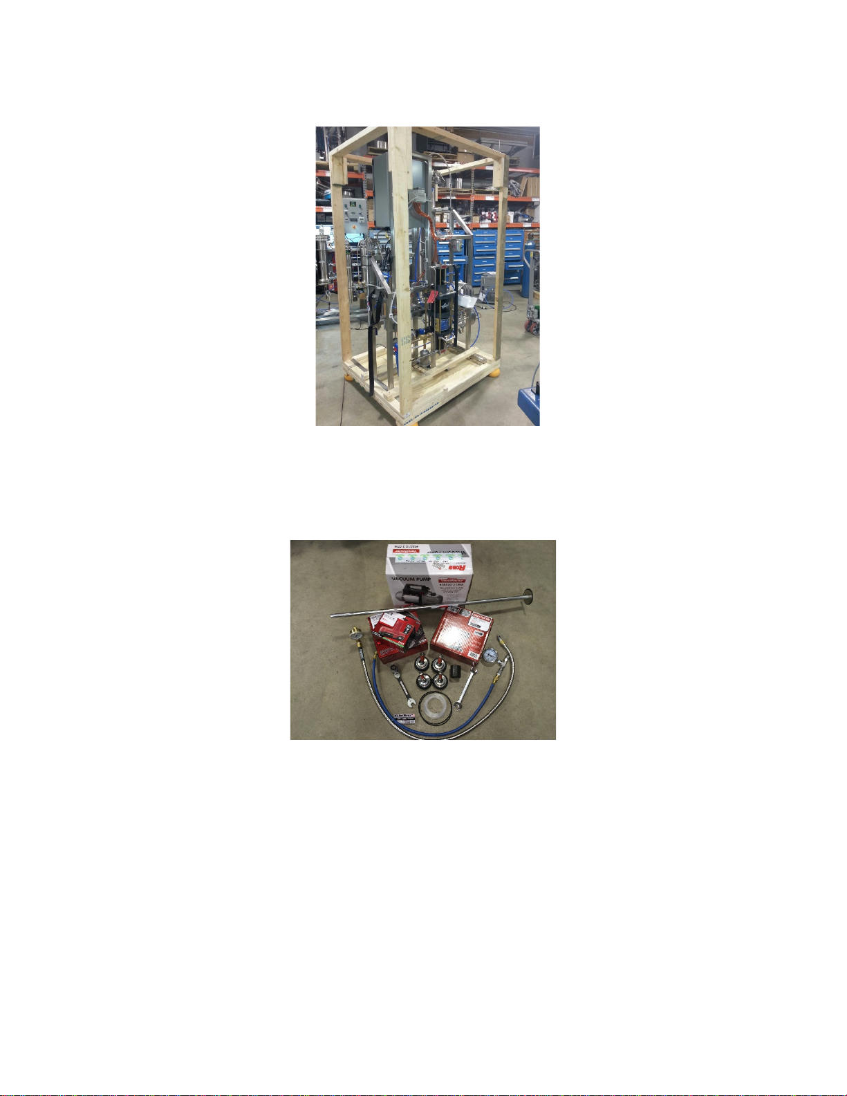
Figure 4. Overview image of support hardware
2.2.3. Remove the horizontal 2x3s from the top of the crate using a hammer or crowbar.
2.2.4. Remove the vertical 2x4s from the four corners of the crate using a hammer or
crowbar.
2.2.5. Remove the two 2x3s running across the top of the system frame and the two
2x3s running alongside the system frame using a Phillips head screwdriver.
Updated 8/8/2018 Copyright Apeks LLC, 2014
6
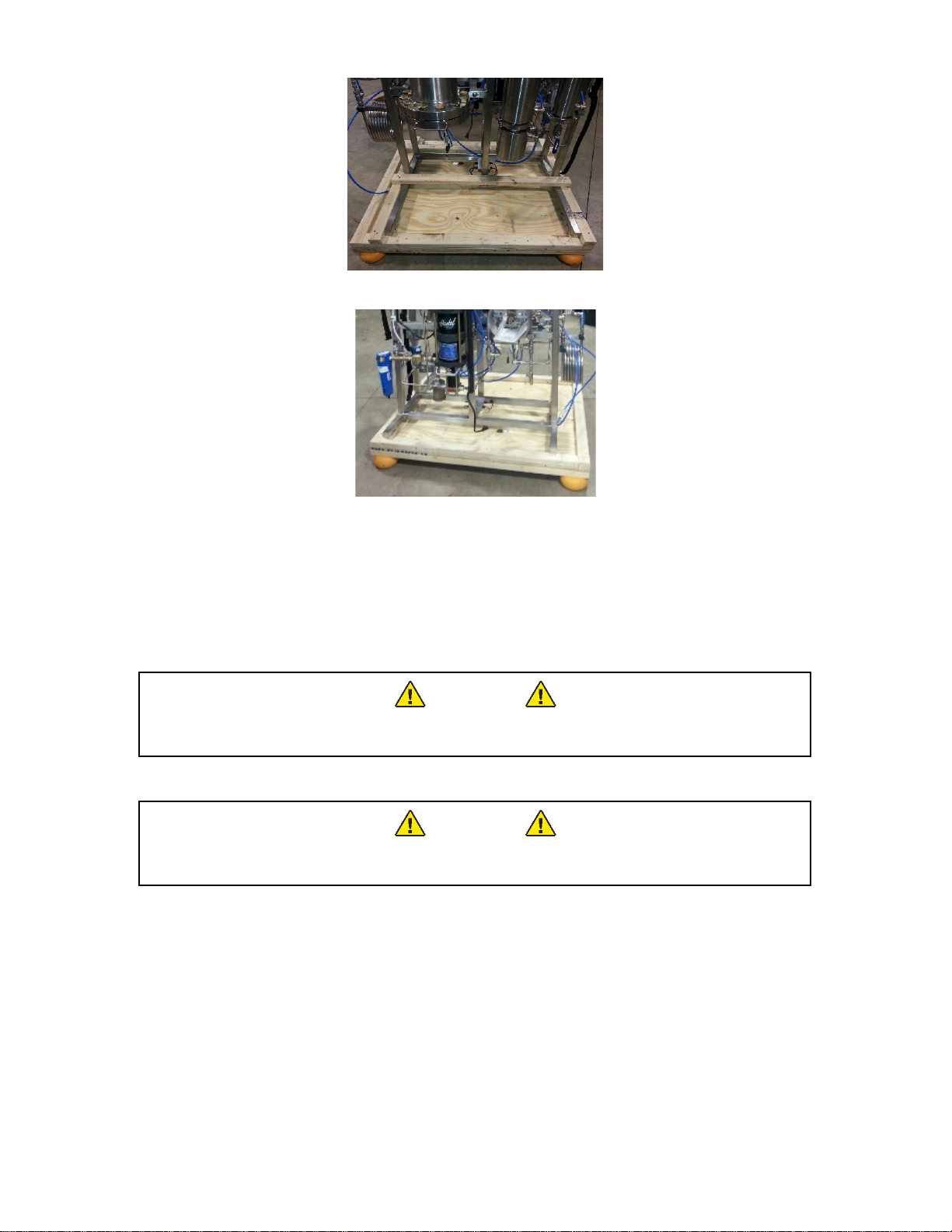
Figure 5. Image of 2x3s support top and sides of system frame
Figure 6. Appearance of crate with 2x3s removed
2.2.1. Using a forklift or pallet jack lift the system off the base of the crate. It may be
necessary to tip the system slightly towards the back in order to slide the forks
under the stainless steel horizontal frame support members.
2.2.1.1. The system weighs in excess of 600-lbs, take extreme caution when lifting or
moving the system. Do not attempt this step without adequate help.
WARNING
The system weighs over 600-lbs (275-kg), use a minimum of three
people to stabilize the system while moving.
2.2.2. Remove the chiller (in cardboard box) from the second crate.
WARNING
The chiller over 120-lbs, use a minimum of two people or a lift cart
when moving the chiller assembly.
2.2.3. Retain the crate and all packing materials for future shipping should the system
ever need to be moved to another facility or shipped back to Apeks.

Updated 8/8/2018 Copyright Apeks LLC, 2014
7
3. System Requirements
3.1. General System Specifications
1500-5L
Extraction System
Chiller/Heater
System
Compressor
Vessel Size (liter)
5-L
15-L
80-Gal
Max Pressure (psi)
1500-psi
100-psi
125-PSI
Operating Temperature (F)
14°F - 122°F
14°F - 122°F
N/A
Dimensions (in)
45 X 30 X 77
28 X 15 X 23
54 X 29 X 61
Weight (lbs)
460-lbs
168-LBS
1000-LBS
Power (V/A/Phase)
110/15/1PH
230/12/1PH
230/40/3PH
1500-20L
Extraction System
Chiller/Heater
System
Compressor
Vessel Size (liter)
20-L
45-L
80-Gal
Max Pressure (psi)
1500-psi
100-psi
125-PSI
Operating Temperature (F)
14°F - 122°F
14°F - 122°F
N/A
Dimensions (in)
45 X 30 X 77
28 X 15 X 23
54 X 29 X 61
Weight (lbs)
460-lbs
168-LBS
1000-LBS
Power (V/A/Phase)
110/15/1PH
230/12/1PH
230/60/3PH
3.2. Facility
3.2.1. Temperature – The 1500-5L and 1500-20L are designed to run in a climate
controlled facility, where the temperature is maintained between 50°F and 85°F.
3.2.2. Dust Control – The 1500-5L and 1500-20L should not be placed in an environment
that has excess dust from other manufacturing operations.
3.2.3. Location – The system is designed to be installed on a concrete or similarly stable
and flat floor.
3.2.4. Compressed Air – Compressed air must be non-lubricated and should be filtered
to between 5μ and 40μ and have a dew point between 0°F and 50°F
3.3. Electrical
3.3.1. The 1500-5L and 1500-20L have three independent electrical requirements; a
110V, 15A, 60Hz, 1 phase NEMA 5-15 male plug for the systems controller, a
220V, 15A, 60Hz, 1 phase NEMA 6-15 male plug for the chiller/heater, and a
hardwired 230-V, 3 phase connection for the air compressor. See chiller and air
compressor manuals for additional electrical requirements.
3.3.1.1. Note that the air compressors can also be ordered prewired for 440-V to
480-V circuits.
WARNING
Do not modify the power connections.
Updated 8/8/2018 Copyright Apeks LLC, 2014
8
3.4. Recirculating Water Chiller/Heater
3.4.1. Recirculating chiller/heater fluid should be a mixture of 50/50 distilled water and
propylene glycol.
WARNING
Do not use Deionized Water
4. Setup and Assembly
1500-5L and 1500-20L system, chiller and air compressor come fully assembled and require
only facility hookup and system interconnect installation.
4.1. Leveling Feet
4.1.1. Use a fork lift or pallet jack to raise the system approximately 6-in off the ground,
use clamps or tie down straps to secure the system to the forks/jack to prevent it
from tipping.
4.1.2. Insert the supplied leveling feet into the four threaded holes on the bottom of the
extraction system. Ensure that the leveling feet are not threaded into the scale
receiver too far or they will hit the frame and negate scale functionality.
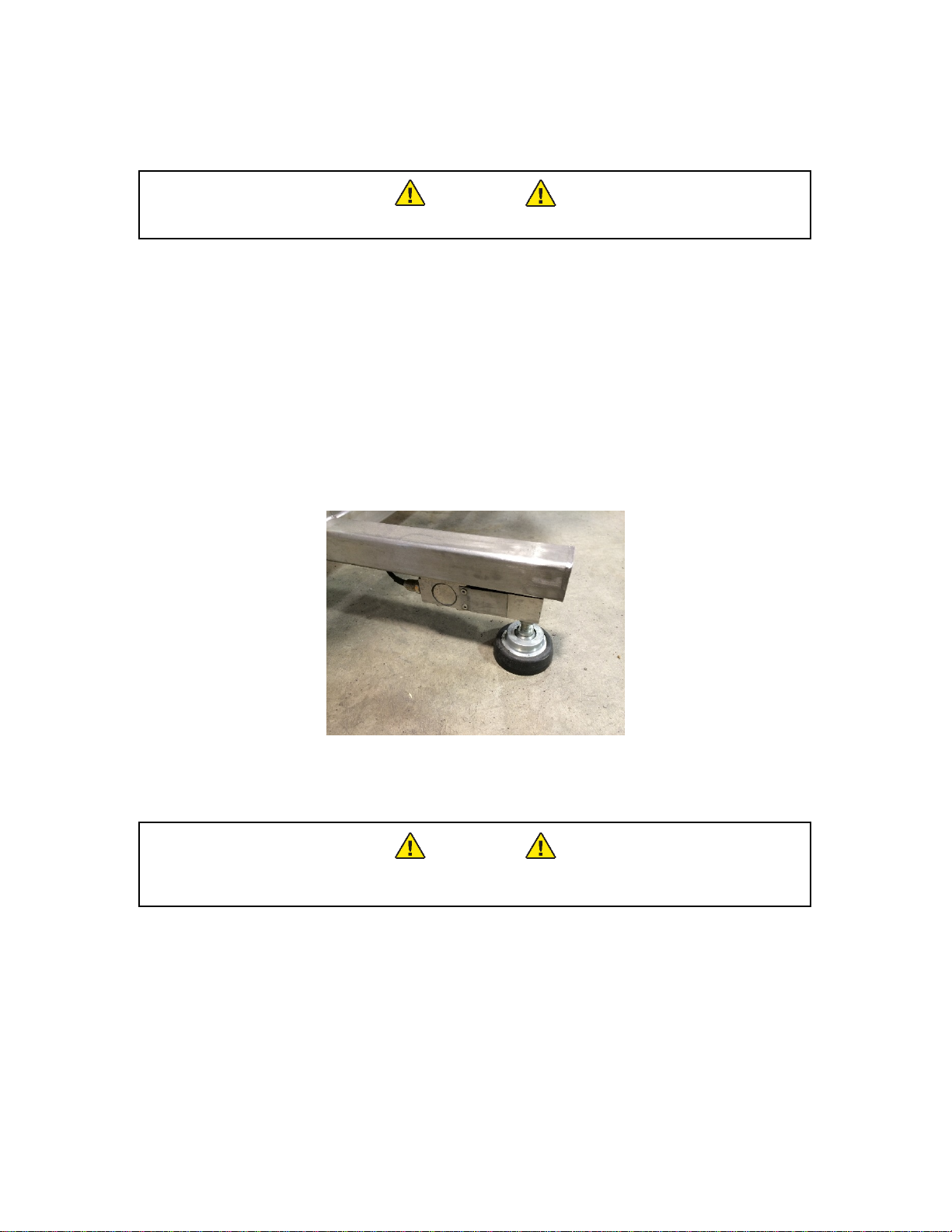
Figure 7. Extraction system leveling feet.
4.2. Coolant Connections
WARNING
Never turn on the chiller without the remote temperature probe
installed and connected to the chiller.
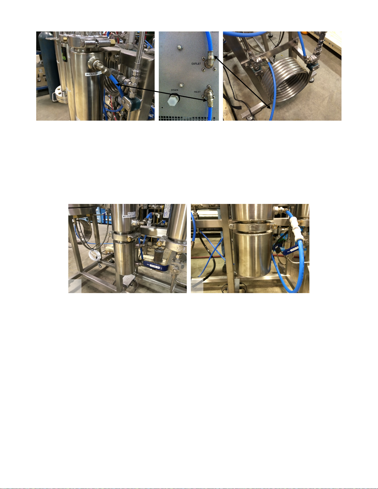
4.2.1. Connect the blue cooling lines to the back of the chiller.
4.2.1.1. Connect the free end of the coiled heat exchanger blue cooling line to the
outlet port on the back of the chiller. Connect the free end of the upper
separator #2 blue cooling line to the inlet port on the back of the chiller.
Updated 8/8/2018 Copyright Apeks LLC, 2014
9
Figure 8. Location and orientation of coolant lines
4.2.2. The separator side of the extraction system will be pre-assembled. In the event
that adjustments need to be made or the system gets taken apart during use, the
water flow path should always be from bottom to top in any vertically oriented
vessel.
4.2.2.1. For systems with a 4-in separator upgrade. The collection cup has baffles
installed that control the coolant flow path. Therefore either cooling line port
on the collection cup can be connected to the inlet or outlet.
Figure 9. Image of separator coolant lines; a) standard separator b) 4-in separator
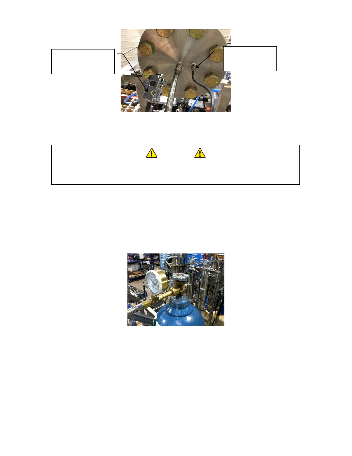
4.2.3. The remote temperature probe is typically pre-assembled into the bottom of the
1500-5L and 1500-20L extraction vessels. If it is not installed or it was removed
after receipt of the system, install the probe into the tube fitting located off center
on the bottom flange of the extraction vessel. The nut on the tube fitting should be
tighten 1/8-turn past finger tight or until it is leak free. Additional instructions
regarding these tube fittings is available at
http://www.swagelok.com/downloads/webcatalogs/EN/MS-13-151.pdf
a
b
Updated 8/8/2018 Copyright Apeks LLC, 2014
10
Figure 10. Location of remote temperature probe on bottom of extraction vessel
4.3. CO2Connections
WARNING
CO2cylinders are under high pressure. Use proper storage and
handling procedures to prevent damage and sudden release of CO2
from the cylinder
4.3.1. CO2used with the 1500-5L and 1500-20L system should be a 99% purity or better
(medical or food grade typically suffice), gas feed, 50-lb, 75-lb or 100-lb high
pressure cylinder.
4.3.1.1. The CO2cylinder connection is a standard CGA-320 and is provided with
the system.
4.3.2. The supplied hose should be connected directly to the CO2cylinder valve. No
regulator is required. A supplied CGA-320 plastic gasket is required to seal the
connection between the hose and the CO2cylinder.
Figure 11. CO2cylinder connection
4.3.3. The CO2line is typically preassembled on the 1500-5L and 1500-20L systems. If
the line was not connected or was removed for cleaning/shipping, reconnect the
line to the tube fitting located on top of Valve 12. The connection is a metal-to-
metal seal and does not require any thread sealant. Tighten 1/8 turn past finger
tight or until leak free.Additional instructions regarding these tube fittings is
available at http://www.swagelok.com/downloads/webcatalogs/EN/MS-13-151.pdf.
Remote
Temperature
Probe
Remote
Temperature Probe
RS232 Connection

Updated 8/8/2018 Copyright Apeks LLC, 2014
11
Figure 12. CO2Hose Connection
4.4. Air System Connections
4.4.1. The air filter and solenoid valve assembly is typically preassembled on the system.
If the assembly was not connected or was removed for cleaning/shipping,
reconnect the assembly using two large crescent wrenches. The fittings are brass
metal to metal seals. Do not over tighten.
Figure 13. Air filter and solenoid assembly
4.4.2. Connect the air compressor to the blue filter using a ½-in male NPT fitting.
4.4.2.1. CO2system air connection is ½” NPT female. Connection to compressed
air should be made through a minimum ½” inner diameter pipe or flexible
hose. Runs longer than 20 feet should be ¾” minimum inner diameter.
4.4.2.2. Always follow the air compressor manufacturer’s operating instructions to
insure proper performance of the compressed air system.
4.5. Electrical Connections
4.5.1. Hardwire the compressor in accordance with the manufacturer’s specifications.
4.5.1.1. Ensure that both the compressor and the refrigerant drier are wired
correctly.
4.5.1.2. The compressor will typically be 230-V or 460-V, 3-Phase. The refrigerant
drier is typically 110-V, 1-Phase.
4.5.2. Plug the extraction system control panel into a 110-V, 15-A standard outlet.
4.5.3. Insert and tighten the remote temperature probe’s RS232 connection into the back
of the chiller in the Remote Probe port.
4.5.3.1. The remote temperature probe and the chiller must be connected whenever
the chiller’s main circuit breaker switch is on. Failure to connect the
thermocouple probe will cause the chiller to stop working and require
CO
2
Cylinder
Hose Connection

Updated 8/8/2018 Copyright Apeks LLC, 2014
12
maintenance from the manufacturer. Damaged caused by operating the
chiller without the remote temperature probe installed and connected will
not be covered by warranty.
WARNING
Do not turn plug in or turn on the chiller with remote probe
disconnected or disconnect the probe while the chiller is under power
Figure 14. Chiller/Heater Remote Temperature Probe Connection
DO NOT TURN ON CHILLER WITH REMOTE PROBE DISCONNECTED OR DISCONNECT PROBE WHILE
CHILLER IS UNDER POWER!
4.6. Chiller/Heater Setup
4.6.1. Attach the supplied cord to the back of the chiller. See Figure 14.
4.6.2. Plug the chiller into a 220-V, 15-A outlet.
4.6.3. It may be necessary to adjust the chiller settings for Remote Probe Control mode.
4.6.3.1. To verify chiller is in Remote Probe Control mode, press the Menu button 5
times until the left display shows “P1” or “P2”
4.6.3.2. If left display shows “P1”, then chiller is in Remote Probe Control mode and
no other adjustments are necessary. Press menu 1 time so the left display
shows water pressure in “psi”.
4.6.3.3. NOTE: When “P1” is displayed on the left screen, the temperature of the
water inside the chiller displayed on the right screen.
4.6.4. If left display shows “P2”, then press and hold menu button for ~3 seconds, press
menu button 6 times until “rP” is displayed on the left, and use the temperature
control knob to adjust the right display setting to “rPC”. Wait for 10 seconds for the
chiller to reset out of the menu mode.
4.6.5. Coolant fluid (50/50 mix of distilled water and propylene glycol) is added to the
system through the reservoir cap on the top of the chiller.
4.6.5.1. After the system is operational, recheck the coolant level (while the system
is running) and add more coolant as necessary.
4.6.6. More detailed operating instructions for the heater/chiller can be found in the
manufacturer’s operating instructions.
Updated 8/8/2018 Copyright Apeks LLC, 2014
13
5. System Operation
The following operating instructions are for the 1500-5L and 1500-20L CO2-basedBotanical Oil
Extraction systems. Instructions assume that chiller and CO2Booster Pump are OEM supplied.
Failure to follow the instructions provided below may void the warranty of the 1500-5L and 1500-
20L systems.
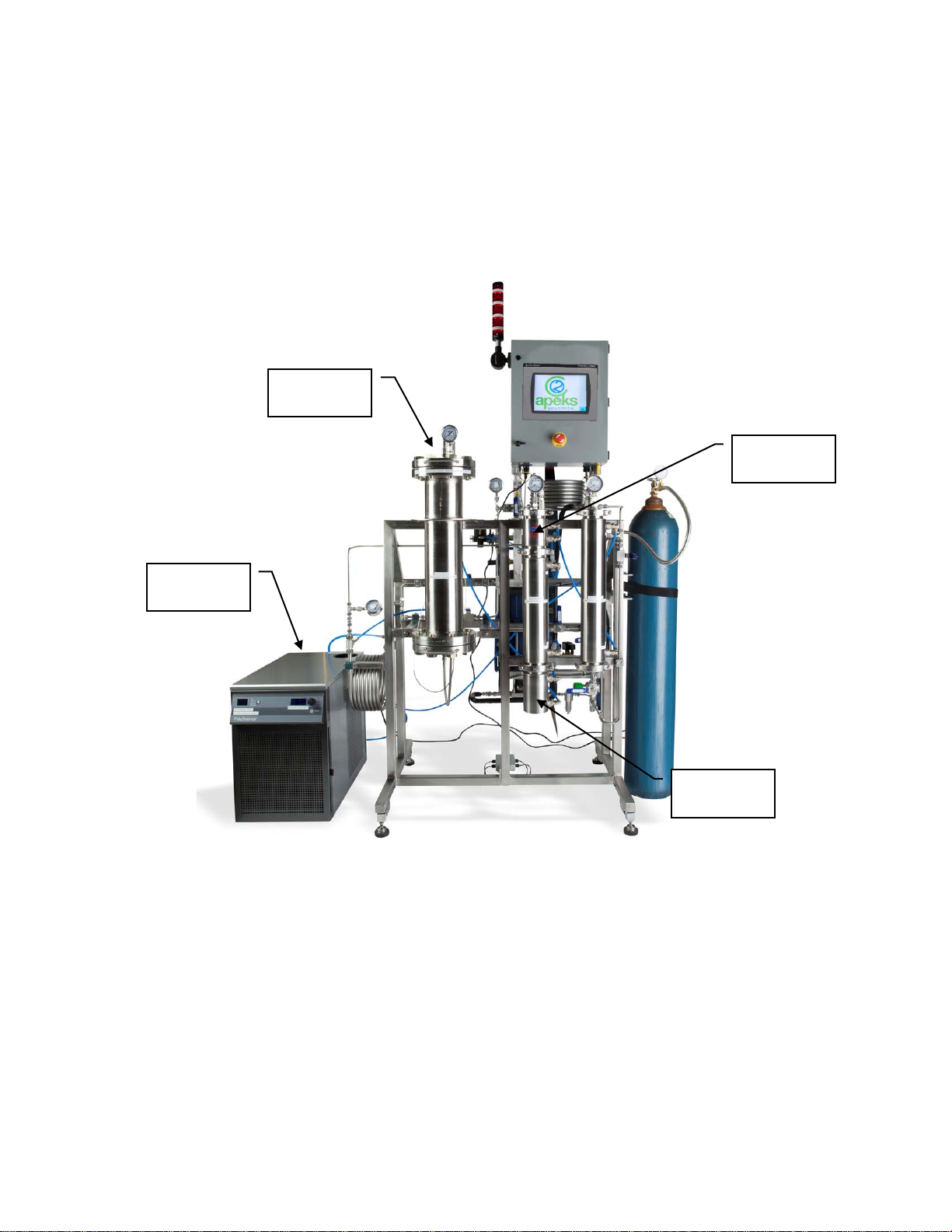
5.1. 1500-5L and 20L Overview
Chiller
Separation
Vessels
Collection
Cup
Extraction
Vessel

Updated 8/8/2018 Copyright Apeks LLC, 2014
14
5.2. Automation Systems Overview
5.2.1. The Human Machine Interface (HMI) is a touch screen. Almost all of the inputs,
outputs and human/machine interactions are managed through the HMI. The
features not controlled or reported through the HMI are the Air Compressor
maintenance schedule and the chiller/heater temperature setting. Refer to their
respective owners manuals for additional operational instructions.
5.2.2. The HMI has two functions; 1) to provide information and 2) to accept inputs from
the operator. The ways to determine if an action is required by the user are
defined below.
5.2.2.1. If a display value or message is colored Red or Orange, an operator must
take and action before progressing forward.
5.2.2.1.1. Red indicates messages indicate that a component of the system has
either failed to reach the minimum operating pressures or temperatures
or that it exceeded the programmed operating limits.
5.2.2.1.2. Orange indicates that an operator activity is required before the Start
button can be depressed. Typically, messages highlighted Orange are
indicative of a scheduled maintenance interval being reached.
5.2.3. Any variable or message that needs to be (or can be) controlled by the operator
are graphically raised to illustrate that the “message” is a button. An example of
the different graphical representations is shown below.
Figure 15. Chiller/Heater Remote Temperature Probe Connection
5.2.1. The controller has safety interlocks preprogrammed into it. These safety interlocks
prevent unsafe operations from occurring by always monitoring the systems
parameters and by removing unsafe action/input control buttons from the HMI.
When buttons appear to be missing from the home screen, it is because the
system is performing an operation that would be unsafe in combination with the
missing button/action.
5.2.2. The HMI will provide message popups (in yellow boxes) to instruct the operator
what steps are required next in order in to complete any action selected. Most
message popups are also acknowledgement buttons that must be pressed before
any further action can be taken.
5.2.3. The primary operating valves on the 1500-5L and 1500-20L are air actuated
valves controlled by the systems controller. In the event of an air compressor
failure or a power failure all air actuated valve will close automatically.
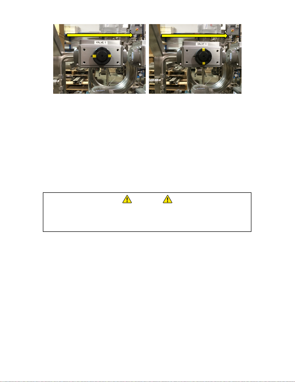
5.2.4. Each air actuated valve has an indicator on the top to inform the operator which
valves are open and which ones are closed. The indicator lines correspond with
the flow direction. The following figure illustrates both and open and closed valve.
Note that it does not matter which way the air actuator is oriented, rather the
direction of CO2flow is important.
Title/Output Display
Input Button
Updated 8/8/2018 Copyright Apeks LLC, 2014
15
Figure 16.a) Valve 1 in the open position, b) Valve 1 in the closed position
5.3. Pre-Cleaning
5.3.1. The 1500-5L and 20L systems are constructed from 304 and 316 stainless steel
and can be cleaned with any cleaner that is compatible with both stainless steel
and your extracted product. Simple Green cleaner, ethanol and acetone work well
for most applications.
5.3.2. The system should be cleaned to the appropriate level (determined by your
application and corresponding regulations) prior to processing each batch of
botanical material.
5.3.2.1. Apeks takes great care to clean all systems prior to shipping, however, it is
the user’s responsibility to ensure that the system meets their required level
of cleanliness.
5.4. Opening Extraction Vessel
WARNING
DO NOT ATTEMPT TO OPEN A VESSEL UNDER PRESSURE!
Always make sure a vent path for the vessel is opened and the
corresponding pressure gauge(s) reads zero prior to loosening the
vessel closure bolts.
5.4.1. This operation cannot be performed during an extraction. The extraction must be
stopped prior to opening the Extraction vessel
5.4.2. From the home screen (see Figure 29), press “Go To Manual Screen” button.
5.4.3. From the manual screen (see Figure 30), press the “Open Extractor Vessel”
button.
5.4.3.1. If the extractor is under pressure, the system will require the operator to
acknowledge that they want to vent all the CO2in the extractor.
5.4.4. When the extractor vessel gauge on top of the vessel and on the home screen
both read zero, it is safe to move to the next step.
5.4.5. Used the supplied impact wrench to remove the bolts from the top or bottom
flange.
5.4.6. Pivot the flange toward the back and let it rest on the integral hinge stops.
5.4.6.1. Use caution not to scratch or otherwise damage the O-ring sealing surfaces
on the flanges.
CO2Flow Direction
CO2Flow Direction

Updated 8/8/2018 Copyright Apeks LLC, 2014
16
Figure 17. Appearance of extractor vessel in open condition, note bolt
can be placed in bolt rack below the flange
5.5. Loading Botanical or Other Media
5.5.1. Material to be extracted is loaded directly into the extraction vessel. The supplied
funnel can be used to help minimize spillage.
5.5.1.1. Typically botanicals perform best in CO2extractions when ground to a
particle size between 50 µin and roughly the consistency of coffee grounds.
5.5.1.2. Any amount of material can be loaded into the Extraction Vessel – the
vessel does not have to be full in order to operate correctly
5.5.2. Gentle compression or packing can be used to increase the amount of material
loaded in the vessel, however heavy compaction should be avoided because it will
cause channeling of CO2during the extraction process.
5.6. Closing Extraction Vessel
5.6.1. Ensure all sealing surfaces are clean and free of debris
5.6.2. Check the O-ring for any visible damage or defects. Replace as necessary
5.6.2.1. The O-ring does not require any lubrication
5.6.3. Close the vessel flange and install each of the closure bolts hand tight
5.6.4. Using the supplied impact wrench and socket, tighten the bolts in a star pattern.
Use the supplied impact wrench with 1-2 second bursts to deliver approximately
50 ft-lbs of torque to each bolt. Heavy torqueing of the bolts is not required.
Figure 18. Torque sequence for 1500-5L and 1500-20L extraction vessels
1
2
3
7
5
8
4
6
2
3
7
8
5
6
4
1
9
10
11
12

Updated 8/8/2018 Copyright Apeks LLC, 2014
17
5.7. Chiller Start Up
5.7.1. Verify chiller’s cooling lines are connected to the extraction system.
5.7.2. Turn chiller on
5.7.2.1. The main power switch is located on the back of the chiller see Figure 14
5.7.2.2. The operations power button is located below the black knob on the front of
the chiller
5.7.3. Set the target temperature to 65°F by quickly depressing the control knob on the
chiller and turning it to the appropriate temperature.
5.7.3.1. In the event that the chiller is displaying temperatures in Celsius, turn off the
main power switch, press and hold the menu button on the front of the
machine and turn on the main power. Then let off the menu button. The
chiller will briefly display dF indicating it is set to display temperature in
degrees Fahrenheit.
5.8. Evacuating the System
5.8.1. From the Home Screen (see Figure 29), click the Manual Screen Button.
5.8.2. From the Manual Screen (see Figure 30), click the Evacuate Button.
5.8.3. Verify that all the gauges on the system display zero pressure.
5.8.4. Verify that the supplied vacuum pump is filled with the appropriate oil.
5.8.4.1. Refer to the vacuum pump owners manual for more detailed information.
5.8.5. Connect the vacuum gauge, blue vacuum hose and vacuum pump to Valve 10 on
the bottom of Separator #2.
Figure 19. Appearance of correctly connected vacuum
gauge, blue vacuum hose and vacuum pump
5.8.1. Open Valve 10.
5.8.2. Turn on the vacuum pump.
5.8.3. Allow the pump to run for approximately 10-min.
5.8.3.1. If the vacuum gauge does not reach -20 in.Hg, either the pump is faulty or
there is a leak in the system.
5.8.4. Close Valve 10.
5.8.5. Turn off the vacuum pump.
5.8.6. Disconnect the vacuum gauge, blue vacuum hose and pump.
5.8.7. Press the message button acknowledging that the evacuation is complete
5.8.7.1. The acknowledgement message button will appear on the Manual Screen
after pressing the Evacuate Button.
5.8.8. Press the Blue Arrow Buttons to select the Go To Home option on the Manual
Screen and press the Return button “enter”.
Updated 8/8/2018 Copyright Apeks LLC, 2014
18
5.9. Conducting an Extraction
5.9.1. Press the Go To Auto Mode Button on the upper left hand corner of the Home
Screen.
5.9.1.1. This resets the controller and enables it to start a new cycle/extraction.
5.9.1.2. The first time you run the system, immediately following a loss of power, or
after any abnormal run conditions the system will default to Manual Mode
for safety.
5.9.2. Verify the chiller is on and target temperature is set to 65°F.
5.9.3. Verify that a 50-lb, 75-lb or 100-lb cylinder of CO2with a sufficient amount of CO2
is connected to the system.
5.9.4. Verify that material is loaded into extraction vessel and extraction vessel is
properly closed
5.9.4.1. The system can be run with no material in the extraction vessel. This can
be used as a way to clean the stainless steel tubing upstream of the
separation vessel.
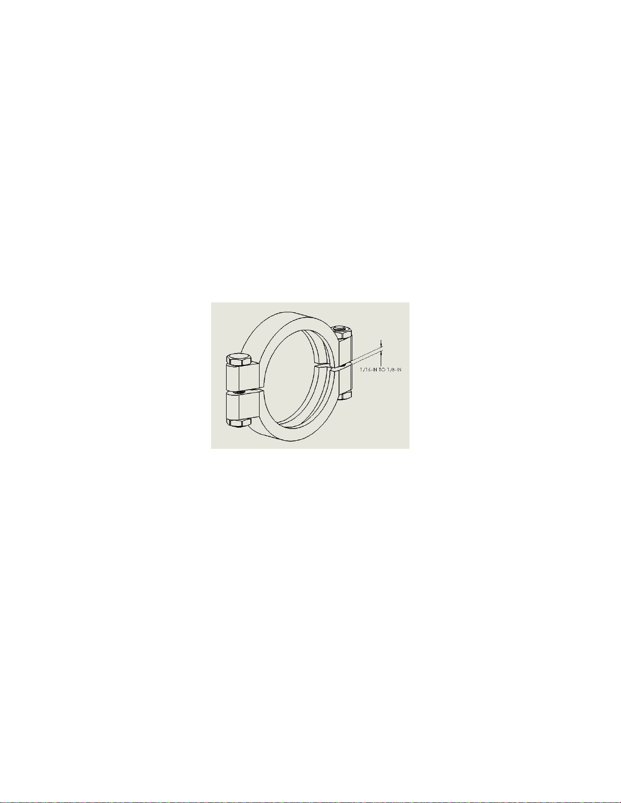
5.9.5. Verify that the Separator vessels are both closed and sanitary clamps are tight
(clamps are considered tight when there is a 1/16-in to 1/8-in between opposing
sides of the clamp)
Figure 20. Appearance of tight sanitary clamp
5.9.6. Press the Start button on the home screen, Figure 29.
5.9.7. After pressing start the system will prompt the operator to;
5.9.7.1. Set Extractor Pressure (between 900-psi and 1400-psi)
5.9.7.1.1. The recommended starting extractor pressure is 1200-psi
5.9.7.2. Set the System Run Time (between 1-hour and 48-hours)
5.9.7.2.1. The recommended run time is 2 hours per pound of botanical
5.9.7.3. Verify the Extractor is properly closed
5.9.7.4. Verify the Separator is properly closed
5.9.7.5. Close Valve 10
5.9.7.6. Open the CO2Bottle
5.9.8. The system will start filling the vessels with CO2to the target extractor pressure.
5.9.8.1. During the filling stage the Home Screen will display a blue box labeled
“Filling” to inform the operator of the systems current activities.
5.9.9. Once the target extractor pressure is reached, the system information box will
change from “Filling” to “Running”. An additional information box will appear
indicating the direction of the flow, either “Forward Flow” or “Reverse Flow”.

Updated 8/8/2018 Copyright Apeks LLC, 2014
19
5.9.9.1. The system routinely switches the flow direction to keep the filters from
clogging with plant material and to prevent the CO2from forming flow
channels inside the plant material.
5.9.10. The system will continue in run mode until it reaches the target run time, at
which point it will begin recovering the CO2into the CO2cylinder. The
information box will switch from “Running” to “Recovering”.
5.9.10.1. The system will prompt the operator to turn up the chiller/heater to 110-F.
This helps to speed up the recovery process.
5.9.10.2. It is not a required step, the system will recover without turning up the
temperature or acknowledging the message.
5.9.10.2.1.Note that increases the chiller/heater temperature also increases the
temperature of the oil in the collection cup.
5.9.11. At the end of recovery the system will have approximately 70-psi in all the
vessels. The system will provide message boxes to instruct the operator
through the final shut down process. The prompts are;
5.9.11.1. Close the CO2cylinder
5.9.11.2. Open Valve 10.
5.9.12. Once the operator acknowledges that the CO2cylinder and Valve 10 are closed,
the system will open all valves, vent any trapped CO2and wait for the next
command.
5.10.Removing Spent Botanical
5.10.1. From the home screen (see Figure 29), press “Go To Manual Screen” button.
5.10.2. From the manual screen (see Figure 30), press the “Open Extractor Vessel”
button.
5.10.2.1. If the extractor is under pressure, the system will require the operator to
acknowledge that they want to vent all the CO2in the extractor.
5.10.3. When the extractor vessel gauge on top of the vessel and on the home screen
both read zero, it is safe to move to the next step.
5.10.4. Used the supplied impact wrench to remove the bolts from the top or bottom
flange.
5.10.5. Pivot the flange toward the back and let it rest on the integral hinge stops.
5.10.5.1. Use caution not to scratch or otherwise damage the O-ring sealing surfaces
on the flanges.
5.10.6. Once the extraction vessel is open, the spent botanical material can be
removed with a dust collector or stainless steel vacuum.
5.10.6.1. Alternatively, the bottom vessel closure can be opened using the same
instructions provided above. With the bottom closure open the botanical
will fall out of the vessel and can be collected in a bag or other collection
device.
5.11.Oil Collection
WARNING
DO NOT ATTEMPT TO OPEN A VESSEL UNDER PRESSURE!
Always make sure a vent path for the vessel is opened and the
corresponding pressure gauge(s) reads zero prior to loosening the
vessel closure bolts.
Updated 8/8/2018 Copyright Apeks LLC, 2014
20
5.11.1. Verify that both Separator vessel gauges read zero and that Valve 10 is open.
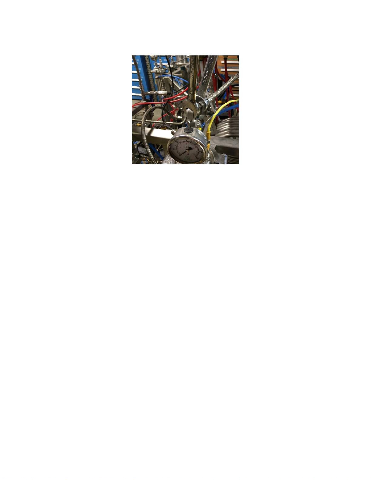
5.11.2. Remove the flexible metal lines from the top of the separators. Use two
wrenches to prevent the NPT fittings from loosening in the separator cap.
Figure 21. Illustration of using two wrenches to remove flexible metal lines
5.11.3. Remove the yellow wire connected to the Separator #1 thermocouple.
5.11.4. Use the 5/8-in ratchet wrench to remove the high pressure sanitary clamps from
the top of both the separator vessels.
5.11.5. Remove the caps from the top of both separator vessels.
5.11.6. Collect any available oil from the separator caps.
5.11.7. Use acetone or alcohol to clean the caps and orifice tube.
5.11.7.1. Separator caps must be cleaned every run.
5.11.8. Use the supplied round squeegee to push any residual oil from the sides of the
separators down to the bottom of the separators.
5.11.9. Use the 5/8-in ratchet wrench to remove the high pressure sanitary clamps from
the bottom of the separator vessels.
5.11.10. Turn off the chiller/heater
5.11.11. Disconnect the two blue water line quick connects on the back of the collection
cup.
5.11.12. Remove the collection cup from Separator #1 and the bottom cap from
Separator #2
5.11.13. Collect the oil from inside the collection cup.
5.11.13.1.Note: there is typically residual dry ice in the collection cup mixed in with the
oil. The dry ice will sublimate without any additional heat. It is sometimes
more efficient to remove the dry ice/oil mixture and place it in collection
device (like a Pyrex dish).
This manual suits for next models
1
Table of contents
Other Apeks Ventilation Hood manuals


Popular Ventilation Hood manuals by other brands


Zanussi
Zanussi ZHG51260GA user manual

GE
GE Monogram ZV1050 installation instructions

CONSTRUCTA
CONSTRUCTA CD939652 Instructions for installation and use

Cooke & Lewis
Cooke & Lewis CLICGS90 manual

Kuppersbusch
Kuppersbusch IKD 976.1GE Instructions for use and installation instructions

NEFF
NEFF I25CBS8W0 Series User manual and installation instructions


