Apeks Force User manual

Version 1, January 2020
Apeks LLC ©
THE FORCE® 5000psi 2 STAGE
Botanical Oil Extraction System
Installation Manual

Apeks Supercritical: The Force® 2 Stage Installation Manual
Scan this QR code to get the most recent version of
the installation instructions:

Apeks Supercritical: The Force® 2 Stage Installation Manual
Table of Contents
1. Critical Safety Overview.................................................................................................................................................... 4
2. Facility Requirements....................................................................................................................................................... 6
Temperature .................................................................................................................................................................... 6
Ventilation and Dust Control ........................................................................................................................................... 6
Foundation ...................................................................................................................................................................... 6
Custom Layout ................................................................................................................................................................. 6
3. When the System Arrives ................................................................................................................................................. 7
Verifying Apeks System Contents List ............................................................................................................................. 7
Receiving the Crates ........................................................................................................................................................ 8
Apeks Labeling .......................................................................................................................................................... 8
TiltWatch and ShockWatch ....................................................................................................................................... 9
Inspecting Crates for Damage ................................................................................................................................... 9
System Layouts............................................................................................................................................................... 10
Unpacking Instructions................................................................................................................................................... 12
Uncrating Extractor Stand and Separator/Control Stand ....................................................................................... 12
Uncrating Diaphragm Compressor .......................................................................................................................... 14
Setup and Assembly ....................................................................................................................................................... 15
Coolant Line and TCU Setup..................................................................................................................................... 15
CO2Connections ...................................................................................................................................................... 20
CO2Vent Connections.............................................................................................................................................. 22
Air Connections ....................................................................................................................................................... 23
Jib Crane Connections.............................................................................................................................................. 25
Electrical Requirements ........................................................................................................................................... 26
Electrical Connections.............................................................................................................................................. 28
Temperature Control Units...................................................................................................................................... 32
E-mail Alerts and Software Updates ........................................................................................................................ 33
4. General Overview and Nomenclature............................................................................................................................ 34
System Overview............................................................................................................................................................ 34
Extractor Vessel Stand ............................................................................................................................................. 36
General System Specifications ....................................................................................................................................... 37
5. References .................................................................................................................................................................... 37
6. Appendices .................................................................................................................................................................... 38
Appendix A: Torque Requirements ............................................................................................................................... 38

Apeks Supercritical: The Force® 2 Stage Installation Manual 4
1. Critical Safety Overview
Please read these IMPORTANT SAFEGUARDS carefully before installing, operating or performing any user-
maintenance activities on the system, and SAVE THESE INSTRUCTIONS to refer to them as needed to ensure continued
safe operation. These instructions are critically important to your safety and proper operation of the system. Failure
to follow these instructions may result in damage to equipment and/or bodily injury.
•Ensure that a qualified safety officer oversees all installation, operation and user-maintenance activities
in accordance with this instruction manual.
•Ensure that only qualified personnel perform all installation, operation and user-maintenance activities in
accordance with this instruction manual.
Note:Qualified personnel are given documented training and should be qualified by the extractor
manufacturer or its designee, or as otherwise required by the Authority Having Jurisdiction (AHJ), prior to
performing any installation, operation or user-maintenance activities. Qualified personnel are to be
experienced in such work and must be aware of and take all safety precautions.
•Our subcritical and supercritical CO2extraction systems operate under high pressure. Operators must be
fully trained and familiar with the systems. Failure to operate these systems correctly can result in a rapid
release of high-pressure CO2and may cause equipment damage and/or bodily injury.
•Our subcritical and supercritical CO2extraction systems use large amounts of CO2during operation. These
systems should be installed in a well-ventilated area to prevent buildup of CO2, which can cause
asphyxiation. Always use a CO2monitor to ensure safe operations.
•WARNING - RISK OF INJURY: Opening a vessel under pressure can result in a rapid release of pressure
and ejection of material from inside the vessel. DO NOT ATTEMPT TO OPEN A VESSEL UNDER PRESSURE!
Always make sure a vent path for the vessel is opened and the corresponding pressure gauge reads zero
prior to loosening the vessel closure. If the handles are difficult to open, this may indicate that the
pressure vessel is still pressurized. Do not force it open. Any pressure in the pressure vessel can be
hazardous.
•WARNING – MAY CAUSE BURNS: Liquified gases are normally stored under pressure. When these liquids
are released to atmospheric pressure, rapid evaporation occurs resulting in reduced temperatures at the
point of evaporation. Exposure of tissue to evaporating liquid can result in freezing and tissue damage.
Precautions should be taken to avoid contact of liquid with eyes, skin, or respiratory system. Tissue
damaged by exposure to evaporating liquid should be treated as frozen tissue (i.e., frostbite). Reference
the Safety Data Sheet (SDS) for more detailed information.
•WARNING – RISK OF INJURY: Check that all components are secured before operating the extraction
system.
•Our subcritical and supercritical CO2extraction systems are designed to operate indoors in a temperature-
controlled environment. Extreme temperatures (below 60°F and above 80°F) will negatively impact the
functionality of the system, chiller, pump and CO2bottles.
•For indoor chiller and cooling system applications, only use propylene glycol and distilled water. Never
use deionized water in the chiller or cooling system for indoor applications. For outdoor chiller and
cooling system applications, use propylene glycol and clean tap water.

Apeks Supercritical: The Force® 2 Stage Installation Manual 5
•Extraction system components can weigh in excess of 2,000 lb. and must be moved carefully. Do not
attempt to move system pieces without the proper equipment, as this could result in serious injury
or death.
•Personal Protective Equipment (PPE) is recommended for persons during setup, operation,
disassembly, and clean-up of the equipment. It is recommended that operators wear the following
PPE:
oChemical-resistant safety goggles;
oGloves;
oEar protection devices;
oFlame-resistant clothing (when working with flammable solvents or in an otherwise
hazardous location);
oClose-toed foot protection; and
oRespirator mask.
•For CE Code-based installations and NEC-based installations, please refer to the following instructions,
as applicable:
oFor CE Code-based installations: “Installations shall be in accordance with the manufacturer’s
installation instructions and CSA C22.1, Canadian Electrical Code, Part 1 (CE Code), National
Fire Code of Canada (NFC), and CSA B149.1, Natural Gas and Propane Installation Code.”
oFor NEC-based installations: “Installation shall be in accordance with the manufacturer’s
installation instructions and NFPA 70, National Electrical Code (NEC), International Fire Code
(IFC), NFPA 1, Fire Code, and NFPA 58, Liquified Petroleum Gas Code.”
•It is the responsibility of the AHJ to verify the suitability of the extractors in the end installation in
accordance with all applicable codes, together with these installation instructions.
FAILURE TO FOLLOW THE INSTALLATION AND OPERATION PROCEDURES PROVIDED IN THIS MANUAL MAY
VOID THE EXTRACTION SYSTEM’S WARRANTY.

Apeks Supercritical: The Force® 2 Stage Installation Manual 6
2. Facility Requirements
Temperature
The Force® 2 Stage system is designed to run in a climate-controlled facility where the temperature is maintained
between 60°F and 80°F. System performance will decrease outside this temperature range, getting progressively
worse as temperatures deviate farther from the recommended range.
Ventilation and Dust Control
The Force® 2 Stage system should be placed in a well-ventilated environment that is free from excess dust from
other manufacturing operations.
Foundation
The Force® 2 Stage systems are designed to be installed on a concrete (or similarly stable) flat floor.
Custom Layout
The Force® 2 Stage systems are designed to be able to be located in different rooms or areas to isolate different
portions of the process. This modulation should be stated during the purchase process, otherwise additional costs
and delays may occur.

Apeks Supercritical: The Force® 2 Stage Installation Manual 7
3. When the System Arrives
Verifying Apeks System Contents List
Every Apeks machine is sent with a system contents list that contains a quality control checklist and a packing slip,
such as the one shown in Figure 3-1.
VERIFY THAT ALL ITEMS ON THE PACKING SLIP HAVE BEEN RECEIVED BEFORE CONTINUING WITH
UNPACKING AND INSTALLATION. CONTACT US IF ANY ITEMS ARE MISSING.
Figure 3-1: Packing Slip

Apeks Supercritical: The Force® 2 Stage Installation Manual 8
Receiving the Crates
Apeks Labeling
An Apeks sticker (such as the one shown in Figure 3-2) should be displayed on the outside of each crate. If the crate
delivered to you does not have an Apeks sticker, please contact us to ensure the crate came directly from Apeks.
Figure 3-2: Shipping Label

Apeks Supercritical: The Force® 2 Stage Installation Manual 9
TiltWatch and ShockWatch
Each crate should have TiltWatch Plus sensors and ShockWatch stickers (such as those shown in Figure 3-3) affixed
on the outside. The TiltWatch Plus Sensors indicate the degree to which the crate may have tilted to the right or
left or if the crate overturned completely during shipping. If the sensors show the crate tilted beyond 30° to the
right or left or overturned completely, please contact us. The ShockWatch sticker is an additional sticker that
indicates if the crate has been mishandled. If the indicator on the ShockWatch sticker is red, please contact us.
Inspecting Crates for Damage
Prior to opening any crate, you should verify that there is no visible external damage. If you notice your crate has
been damaged, be sure to note the damage on the applicable Proof of Delivery, and please contact us to report the
damage.
Figure 3-3: TiltWatch Label and ShockWatch Sticker

Apeks Supercritical: The Force® 2 Stage Installation Manual 10
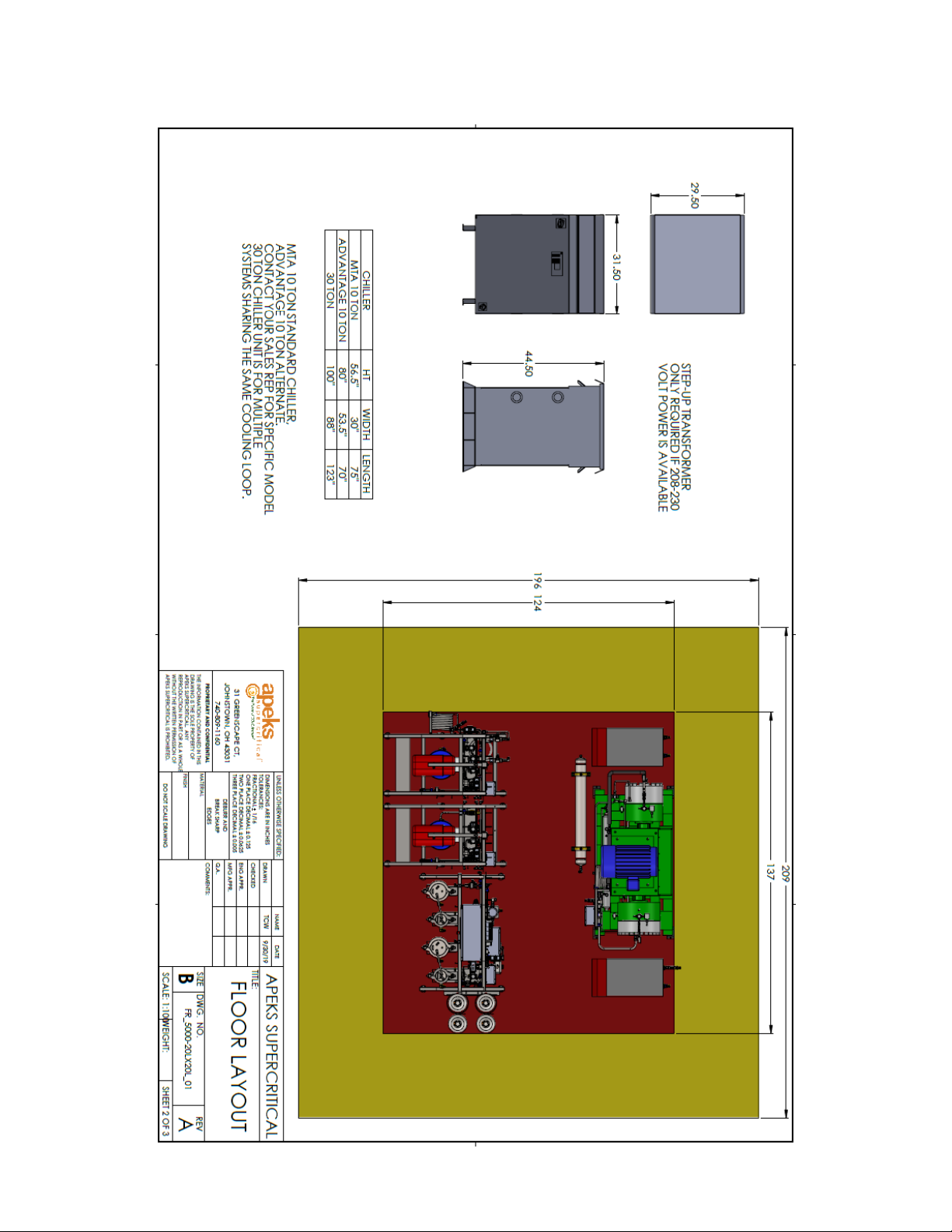
The Force® 5000psi 2 Stage Standard Layout
Applicable to 20Lx20L and 40Lx40L Systems
Apeks Supercritical: The Force® 2 Stage Installation Manual 11
The Force® 5000psi 2 Stage Floor Layout
Applicable to 20Lx20L and 40Lx40L Systems
Apeks Supercritical: The Force® 2 Stage Installation Manual 12
Unpacking Instructions
WARNING:Each crate contains heavy components. Do not attempt to lift without the proper equipment.
Uncrating Extractor Stand and Separator/Control Stand
To uncrate the extractor and separator/control stand, first, remove the sides and top of the shipping crate. Then,
remove the wooden tie downs that keep the system attached to the skid. See Figure 3-4.
Figure 3-4: Wood Tie-Downs
Wood Tie-Downs
Apeks Supercritical: The Force® 2 Stage Installation Manual 13
Carefully use a forklift to remove the stand from the skid. The stand has features designed specifically to be used
with a forklift to properly remove the stand from the skid. See Figure 3-5.
WARNING:Lifting the extractor and/or separator/control stands from anywhere but the labeled pickup
locations can lead to equipment damage and/or serious injury or death.
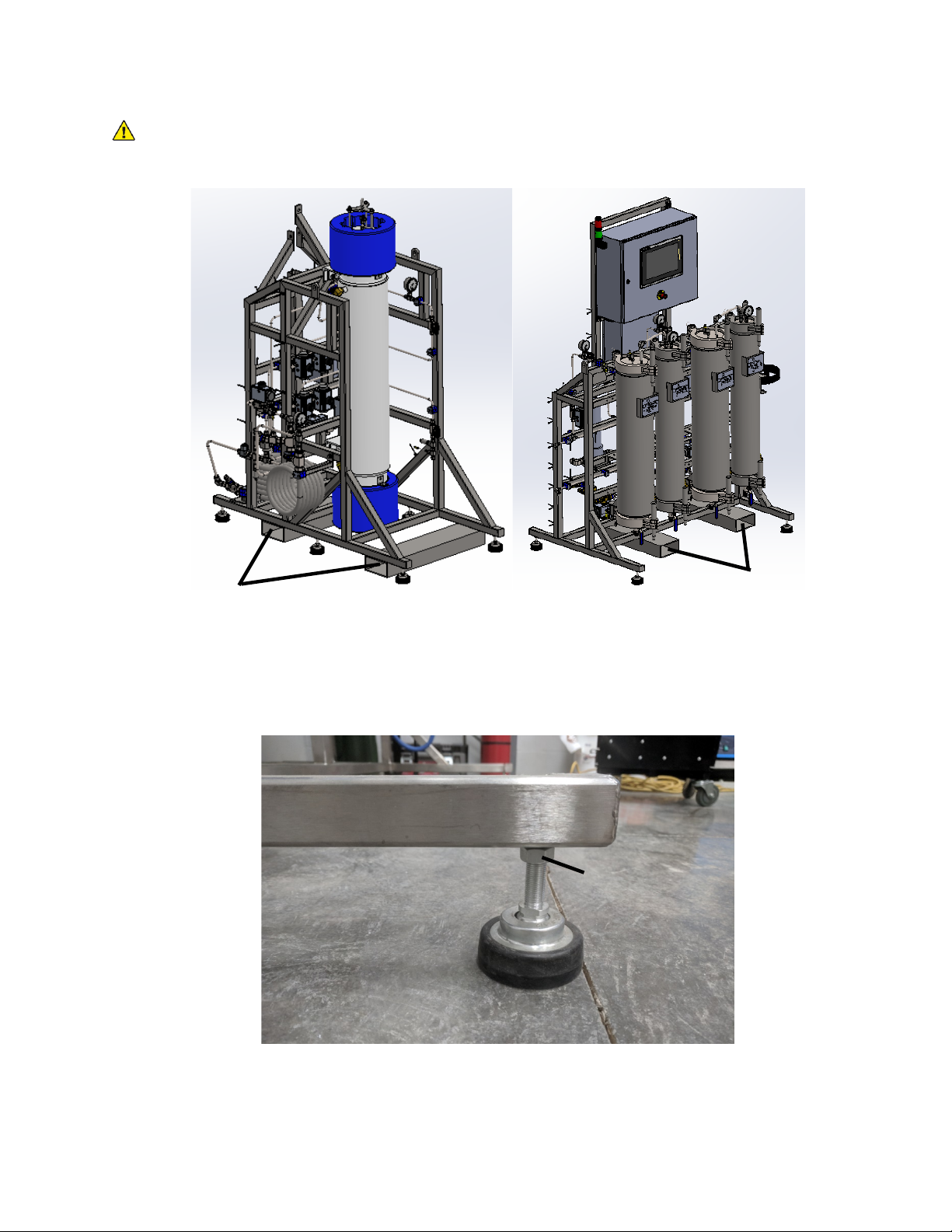
Attach the four leveling feet to each stand before lowering the stand. Once the system is on the ground, use the
leveling feet to level the system and then snug the jam nut against the stand to secure the feet. See Figure 3-6.
Jam Nut
Figure 3-6: Leveling Feet
Figure 3-5: Forklift Insert Features
Insert Forklift Here
Insert Forklift Here

Apeks Supercritical: The Force® 2 Stage Installation Manual 14
Uncrating Diaphragm Compressor
To uncrate the diaphragm compressor, first, remove the sides and top of the shipping crate. Then, remove the lag
screw/bolts that keep the diaphragm pump attached to the skid. See Figure 3-7.
Carefully use a forklift to remove the diaphragm compressor from the shipping crate. The diaphragm compressor
stand is labeled with proper forklift pickup locations.
WARNING:Lifting the diaphragm compressor from anywhere but the labeled pickup locations can lead to
equipment damage and/or serious injury or death.
Once the diaphragm compressor is off the shipping crate, attach the four rubber vibration dampening feet to the
four corners of the pump. See Figure 3-8. Anchor the diaphragm compressor to the floor with concrete lags or
other suitable hardware.
Figure 3-7: Diaphragm pump on skid, in partially disassembled crate
Figure 3-8: Vibration Dampening Feet

Apeks Supercritical: The Force® 2 Stage Installation Manual 15
Setup and Assembly
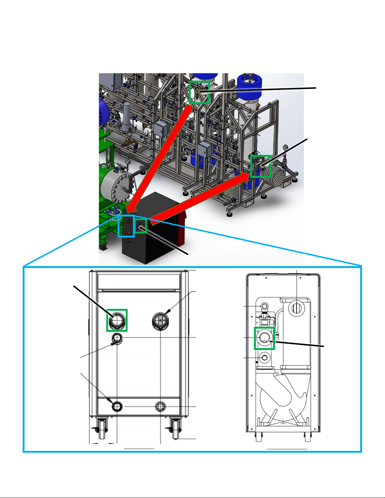
Coolant Line and TCU Setup
The separator coolant loop will incorporate the Separator Temperature Control Unit (TCU), the diaphragm
compressor, and the separator vessel/control stand.
The hose on the separator TCU delivery will connect to the water flow switch on the separator stand.See Figure
3-9.
Separator TCU
Separator TCU Delivery
Water Flow Switch
Figure 3-9: Separator TCU Delivery to Water Flow Switch
Apeks Supercritical: The Force® 2 Stage Installation Manual 16
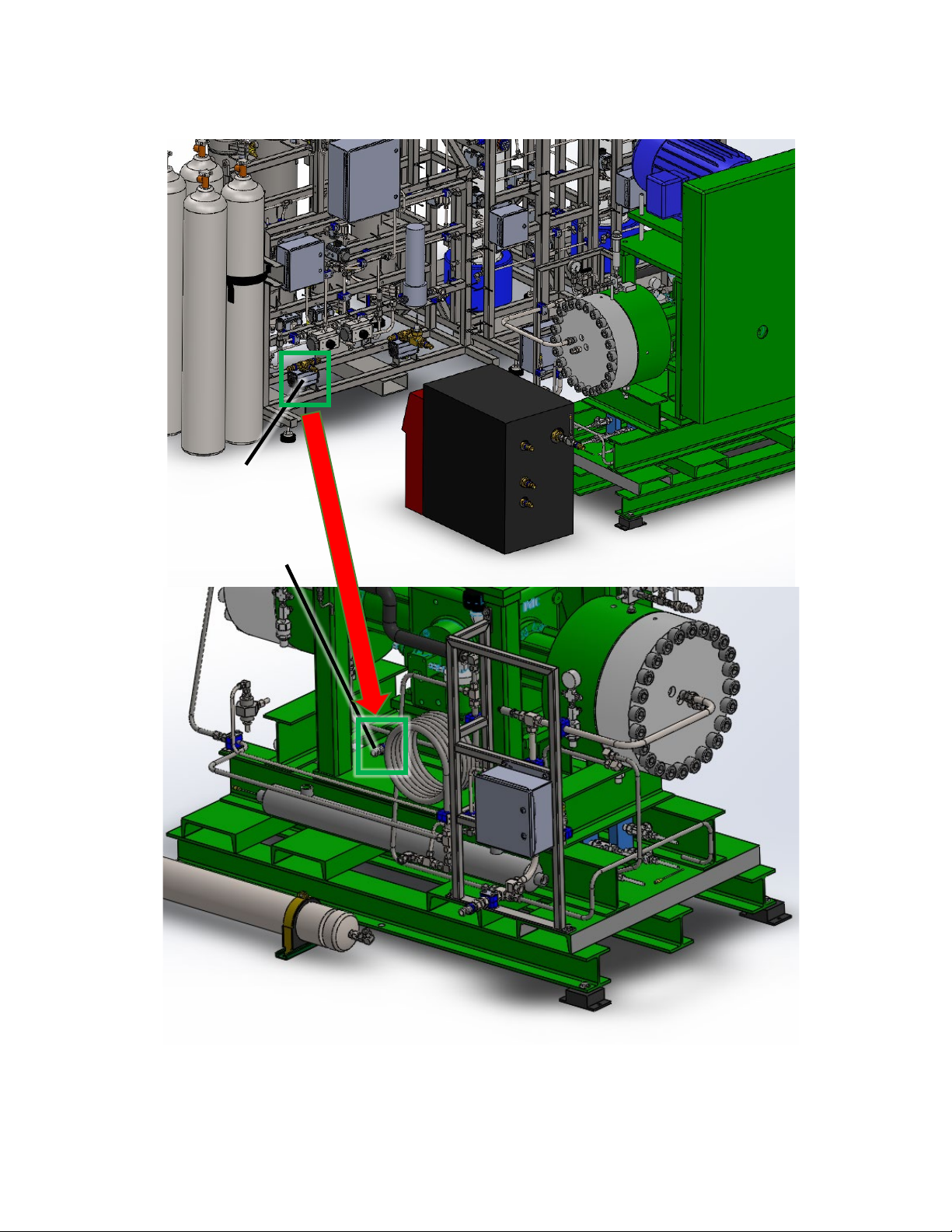
The hose from the back of the separator stand at valve 18B will connect to the oil heat exchanger on the base of the
diaphragm compressor stand. See Figure 3-10.
Valve 18B
Oil Heat Exchanger Inlet
Figure 3-10:Valve 18B to Oil Heat Exchanger Inlet

Apeks Supercritical: The Force® 2 Stage Installation Manual 17
The hose from the regenerative heat exchanger on the diaphragm compressor will connect to the process return
line on the separator TCU.The return line connection to the TCU will depend on the installed TCU. See Figure 3-11.
Regenerative Heat
Exchanger Outlet
Separator
TCU
Return
Figure 3-11:Regenerative Heat Exchanger Outlet to Separator TCU Return
OR
Separator
TCU
Return
Delta T TCU
Advantage TCU
Apeks Supercritical: The Force® 2 Stage Installation Manual 18
The extractor coolant loop will incorporate the extractor TCU and the extractor vessel stand.
The hose on the extractor TCU delivery will connect to the temperature control heat exchanger on the extractor
stand. The hose from the flow switch on the extractor stand will connect to the process return line on the extractor
TCU. The return line connection to the TCU will depend on the installed TCU. See Figure 3-12.
Extractor TCU Delivery
Extractor TCU
Return
Temperature
Control Heat
Exchanger
Flow Switch
Figure 3-12:Extractor TCU Coolant Line Setup
OR
Extractor
TCU
Return
Delta T TCU
Advantage TCU
Apeks Supercritical: The Force® 2 Stage Installation Manual 19
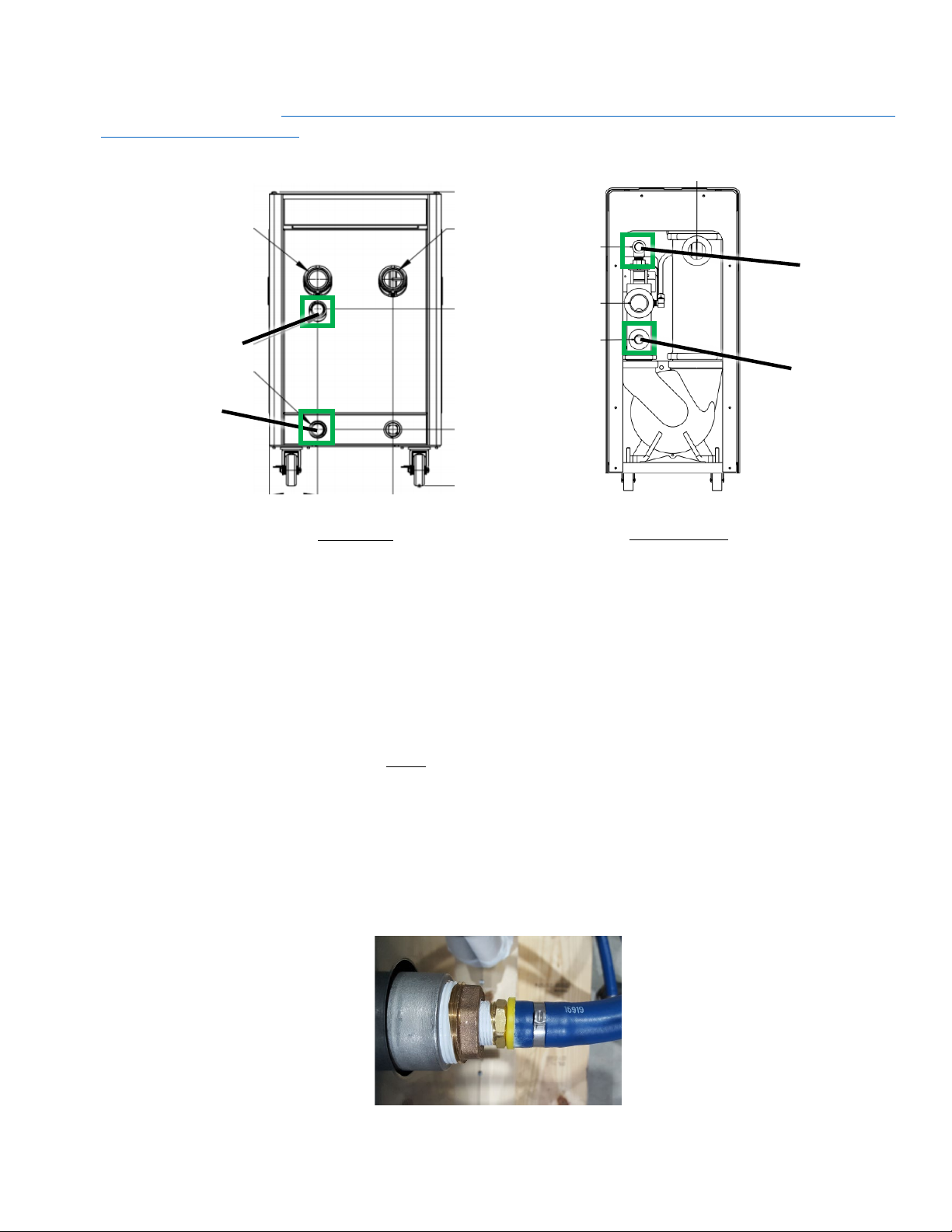
For outdoor chillers, please refer to the Outdoor Chiller Layout Guide.The Outdoor Chiller Layout Guide can be
found on our website: https://www.apekssupercritical.com/wp-content/uploads/2019/10/OUTDOOR-CHILLER-
LAYOUT-GUIDE_10.2019.pdf
Water supply and drain lines for outdoor chiller setups should be connected via the connections shown in Figure 3-
13. Connections will differ based on the installed TCU.
Water drain and supply hoses require additional setup instructions for installation onto the extractor and separator
TCUs.
Tools and supplies recommended for installation:
•Tube cutters
•Silicone lubricating grease
•Hose clamp for 1.07” outer diameter hose
•Clamp tool for tightening clamp (Note: Tool will depend on clamp applied.)
Water Drain and Supply Hose Installation Steps:
1. Cut hose to necessary length for facility.
2. Place clamp over hose. DO NOT TIGHTEN CLAMP.
3. Apply silicone lubricant on the inner diameter of hose.
4. Insert hose over barb fitting on TCU.
5. Slide clamp up tube until it is situated over barbed fitting.
6. Tighten clamp.
Installed hose connection will look like that shown in Figure 3-14.
Figure 3-13:Outdoor Chiller TCU Coolant Line Setup
Water
Supply
Water Drain
Delta T TCU
Advantage TCU
OR
Water Drain
Water Supply
Figure 3-14:TCU Water Drain and Supply Hose Connection

Apeks Supercritical: The Force® 2 Stage Installation Manual 20
CO2Connections
Use supplied CO2bottle valve gaskets when connecting bottles to the system. There are 13 CO2lines to be
connected on The Force® 2 Stage system.Avoid kinks and abrasion when routing the CO2hoses.
There is one braided stainless-steel line (in the standard configuration) from the separator stand to the diaphragm
compressor suction line. This connection is a 36" long stainless steel braided flexible line with ¾" compression
fittings. See Figure 3-15.
There are two 36” long black nylon flexible lines with ½" compression fittings. One hose goes between the outlet of
the diaphragm compressor and one port on the accumulator vessel. One hose goes between the other port on the
accumulator vessel and the inlet port on extractor B. See Figure 3-16.
Figure 3-15:Separator Stand to Compressor
Figure 3-16:Diaphragm Compressor to Extraction Vessel
Accumulator
Table of contents
Other Apeks Ventilation Hood manuals


Popular Ventilation Hood manuals by other brands

Bosch
Bosch DWW092460B Installation Instructions Operating and installation instructions

AEG
AEG DF7190 user manual

Broan
Broan Elite EI5936SS instructions

Whirlpool
Whirlpool GZ5730XR Series Dimensions

Westinghouse
Westinghouse QR061W owner's manual

Franke
Franke FTU 3807 W Installation instructions use and care guide


