ApenGroup PCH Series Manual

1cod. HG0131.10GB ed.A-2205
PCH
ErP
2021
Compliant
EU/2016/2281
EN Maintenance and service manual of
PCH condensing warm air heater module
This manual cannot be copied in part or in full for disclosure to third parties without the prior written consent by Apen Group s.p.a.
NEW VERSION
CPU G26800
TRANSLATION OF ORIGINAL Manual

Condensing warm air heater module PCH
APEN GROUP SPA reserves the right to make changes deemed to be required to its products or documentation
2
cod. HG0131.10GB ed.A-2205 PCH 3cod. HG0131.10GB ed.A-2205
PCH
VER. 01.2020
CODE SERIAL NUMBER
Dichiarazione di Conformità
Statement of Compliance
APEN GROUP S.p.A.
20060 Pessano con Bornago (MI)
Via Isonzo, 1
Tel +39.02.9596931 r.a.
Fax +39.02.95742758
Internet: http://www.apengroup.com
Il presente documento dichiara che la macchina:
With this document we declare that the unit:
Модели:
Model:
Generatore d’aria calda: modulante a condensazione PCH
Warm Air Heater: PCH modulating and condensing
è stata progettata e costruita in conformità con le disposizioni delle Direttive Comunitarie:
has been designed and manufactured in compliance with the prescriptions of the following EC Directives:
Regolamento Apparecchi a Gas 2016/426/UE
Gas Appliance Regulation 2016/426/UE
Direttiva compatibilità elettromagnetica 2014/30/UE
Electromagnetic Compatibility Directive 2014/30/UE
Direttiva Bassa Tensione 2014/35/UE
Low Voltage Directive 2014/35/UE
Regolamento ErP 2281/2016/UE
ErP Regulation 2281/2016/UE
Direttiva ROHS II 2011/65/UE e ROHS III 2015/863/UE
ROHS II 2011/65/UE and ROHS III 2015/863/UE Directives
è stata progettata e costruita in conformità con le norme:
has been designed and manufactured in compliance with the standards:
EN17082:2019
EN60335-1
EN60335-2-102
EN60730-1
EN 60068-2-1
EN 60068-2-2
EN55014-1
EN55014-2
EN61000-3-2
EN61000-3-3
Organismo Notificato:
Notified body:
Kiwa Cermet Italia S.p.A
0476
PIN 0476CQ0451
La presente dichiarazione di conformità è rilasciata sotto la responsabilità esclusiva del fabbricante
This declaration of conformity is issued under the sole responsibility of the manufacturer
Pessano con Bornago
01/10/2020 Apen Group S.p.A.
Un Amministratore
Mariagiovanna Rigamonti

APEN GROUP SPA reserves the right to make changes deemed to be required to its products or documentation
Condensing warm air heater module PCH
2
cod. HG0131.10GB ed.A-2205 PCH 3cod. HG0131.10GB ed.A-2205
PCH
VER. 07.2022
CODE SERIAL NUMBER
UK Declaration of Conformity
APEN GROUP S.p.A.
20042 Pessano con Bornago (MI)
Via Isonzo, 1 - ITALY
Tel +39.02.9596931 r.a.
Fax +39.02.95742758
Internet: http://www.apengroup.com
With this document we declare that the unit:
Model:
Warm Air Heater: PCH modulating and condensing
has been designed and manufactured in compliance with the prescriptions of the following Regulations:
Regulation 2016/426 on gas appliances as brought into UK law and amended
Electromagnetic Compatibility Regulations 2016
Electrical Equipment (Safety) Regulations 2016
The Restriction of the Use of Certain Hazardous Substances in Electrical and Electronic Equipment
Regulations 2012
ErP Regulation 2016/2281/UE
has been designed and manufactured in compliance with the standards:
EN17082:2019
EN60335-1
EN60335-2-102
EN60730-1
EN 60068-2-1
EN 60068-2-2
EN55014-1
EN55014-2
EN61000-3-2
EN61000-3-3
Notified body:
Kiwa UK
0558
PIN 0476CQ0451
This declaration of conformity is issued under the sole responsibility of the manufacturer
Pessano con Bornago
19/07/2022 Apen Group S.p.A.
Un Amministratore
Mariagiovanna Rigamonti

Condensing warm air heater module PCH
APEN GROUP SPA reserves the right to make changes deemed to be required to its products or documentation
4
cod. HG0131.10GB ed.A-2205 PCH 5cod. HG0131.10GB ed.A-2205
PCH
INDEX
SECTION 1. GENERAL CAUTIONS ................................................................. 5
SECTION 2. SAFETY INSTRUCTIONS ............................................................ 5
2.1 Fuel............................................................................................................ 5
2.2 Gas Leaks ................................................................................................. 5
2.3 Power Supply ............................................................................................ 6
2.4 Use ............................................................................................................ 6
2.5 Maintenance .............................................................................................. 6
2.6 Transport and handling.............................................................................. 6
2.7 Unpacking.................................................................................................. 7
2.8 Disposal and demolition ............................................................................ 7
2.9 Installation ................................................................................................. 7
SECTION 3. TECHNICAL DATA........................................................................ 8
3.1 Regulation (EU) 2016/2281 ....................................................................... 11
SECTION 4. OPERATING CYCLE .................................................................... 12
4.1 Air/gas premixing operation....................................................................... 13
SECTION 5. USER INSTRUCTIONS................................................................. 14
5.1 Operation of the Heater ............................................................................. 14
5.2 Interface Panel .......................................................................................... 14
5.3 Reset ......................................................................................................... 16
5.4 Flame Indication LED ................................................................................ 16
5.5 Modulation PCB parameters ..................................................................... 19
5.6 Analysis of Lockouts - Exx......................................................................... 24
5.7 Connections to the Flue............................................................................. 27
5.8 Condensate drain ...................................................................................... 29
5.9 Gas Connection......................................................................................... 30
....................................................................... 35
5.11 Combustion Analysis ................................................................................. 36
5.12 Conversion to LPG .................................................................................... 36
5.13 Conversion to gas G25 - G25.1 - G27....................................................... 37
5.14 Conversion to gas G2.350......................................................................... 37
5.15 Replacing the gas valve ............................................................................ 37
5.16 CPU modulation PCB replacement ........................................................... 38
SECTION 6. MAINTENANCE ............................................................................ 38
SECTION 7. WIRING DIAGRAMS..................................................................... 40
SECTION 8. ANALYSIS OF FAULTS ................................................................ 41
SECTION 9. LIST OF SPARE PARTS............................................................... 42
9.1 Parts for the electrical panel ...................................................................... 42
9.2 Parts for the burner unit............................................................................. 43
9.3 Other spare parts available ....................................................................... 44

APEN GROUP SPA reserves the right to make changes deemed to be required to its products or documentation
Condensing warm air heater module PCH
4
cod. HG0131.10GB ed.A-2205 PCH 5cod. HG0131.10GB ed.A-2205
PCH
1. GENERAL CAUTIONS
This manual is an integral part of the product and must always
accompany it.
Should the equipment be sold or passed on to someone else,
always make sure that this manual is supplied with the equipment
for future reference by the new owner and/or installer.
The manufacturer shall not be held civilly or criminally responsible
for injuries to people or animals or damages to things caused
by incorrect installation, calibration and maintenance or by
failure to follow the instructions contained in this manual or by
This product must be used only for the applications for which
it was designed or approved. Any other use must be regarded
as hazardous. Improper use may impair the operation, service
life and safety of the unit.
During the installation, operation and maintenance of the
equipment described in this manual, the user must always
strictly follow the instructions given in all the chapters of this
use and instruction manual.
The condensing warm air heater must be installed
in compliance with current regulations, according to
the manufacturer's instructions and by qualied sta,
technically specialised in the heating eld.
ATTENTION:Due to the physics of the thermal exchange
and the intrinsic functioning of the PCH modules, the
surface temperatures of the exchanger, as they depend
on dierent factors such as the installation of the module
inside the AHU/Roof-top unit and the dimensioning of
the air distribution ducts and/or terminals cannot be
guaranteed by the controls on board the PCH alone.
If the PCH modules are used in combination with
ammable or slightly ammable refrigerant gases (A2L),
precautions must be taken to ensure that accidental
refrigerant leaks do not lead to dangerous situations. In
case of doubt, please contact APEN GROUP SPA
maintenance operations must be carried out only by suitably
requisites required by the regulations in force in their country.
Maintenance must be carried out with methods and timescales
in compliance with the regulations in force in the country where
the appliance is installed.
For Italy, the “technical service” tab ofApen Group website www.
apengroup.com indicates several Technical Service Centres
and maintenance of the product carried out according to law
37/2007 (ex 46/90)
For more information, visit our website www.apengroup.com or
contact Apen Group directly.
supplied with this equipment.
2. SAFETY-RELATED WARNINGS
This chapter describes the safety instructions to be followed
by machine operators.
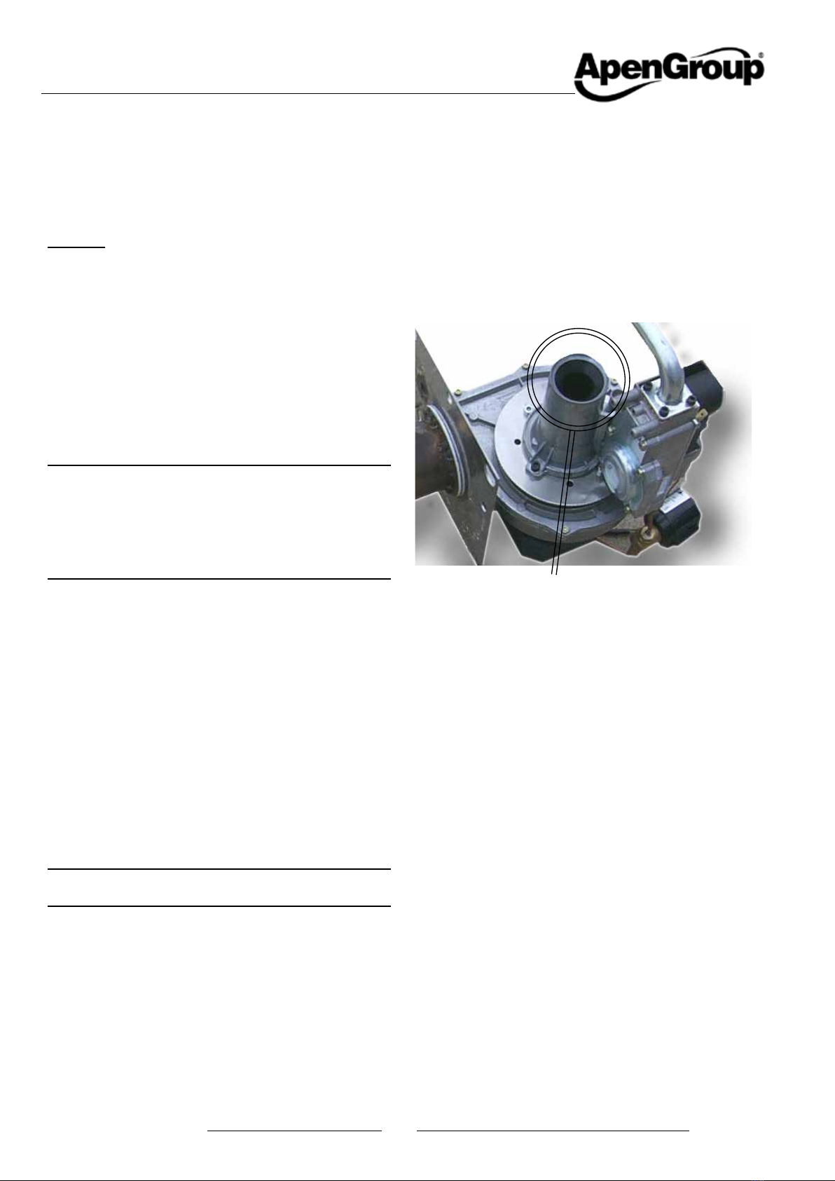
2.1. Fuel
Before starting up the heater, make sure that:
• the gas mains supply data are compatible with the data
stated on the nameplate;
•
• the combustion air is supplied in such a way as to avoid
even partial obstructions of the intake grille (caused by
leaves etc.);
• the gas seal of the feeding system has been tested and
approved in compliance with the applicable standards;
• the heater is supplied with the same type of fuel it has
been designed for;
•
applicable standards;
• the inside of the gas pipes and air distribution ducts for
ducted heaters have been thoroughly cleaned;
•
heater;
•
on the nameplate.
2.2. Gas Leaks
If you smell gas:
• do not operate electrical switches, the telephone or any other
•
to vent the gas out of the room;
• close the gas valves;
•
the unit;
• move away from the unit
• call for qualied sta.
• call the Fire Brigade.
NOTE: IT is strictly prohibited to supply gas to the circuit
with pressures higher than 60 mbar. Such pressures
could cause the valve to break

Condensing warm air heater module PCH
APEN GROUP SPA reserves the right to make changes deemed to be required to its products or documentation
6
cod. HG0131.10GB ed.A-2205 PCH 7cod. HG0131.10GB ed.A-2205
PCH
HG0030.00_IM 001
2.3. Power supply
system, made in compliance with current regulations (IEC 64-8,
applies to Italy only).
Cautions.
•
• Check that the mains power supply is the same as the
power input stated on the equipment nameplate and in
this manual.
• Do not mistake the neutral for the live wire.
• The heater can be connected to the mains power supply
with a plug-socket only if the latter does not allow live and
neutral to be swapped.
•
section, must be suitable for the equipment maximum
power input, shown on the nameplate and in this manual.
• Do not pull electric cables and keep them away from heat
sources.
NOTE: IT is compulsory to install, upstream
of the power cable, a fused multipole
switch with contact opening wider than 3mm.
The switch must be visible, accessible
and less than 3m away from the control board.
All electrical operations (installation and maintenance)
must be carried out by qualied sta.
2.4. Use
Do not allow children or inexperienced people to use any
electrically powered equipment.
The following instructions must be followed:
• do not touch the equipment with wet or damp parts of your
body and/or with bare feet;
• do not leave the equipment exposed to the elements (rain,
sun etc...) unless it is adequately protected;
• do not use the gas pipes to earth electrical equipment;
•
gas duct;
•
• do not place any object over the equipment;
• do not touch the moving parts of the heater.
2.5. Maintenance
Maintenance operations and combustion inspections
must be carried out in compliance with current standards.
Before carrying out any cleaning and maintenance operations,
isolate the boiler from the mains power supply using the switch
located on the electrical system and/or on the shut-out devices.
and do not attempt to repair it yourself, but contact our local
Technical Service Centre.
All repairs must be carried out by using genuine spare parts.
Failure to comply with the above instructions could compromise
the safety of the equipment and invalidate the warranty.
If the equipment is not used for long periods, shut the gas
power supply.
If the heater is to be put out of service, in addition to the above
operations, potential sources of hazard on the unit must be
disabled.
It is strictly forbidden to obstruct the Venturi pipe inlet, located
on the burner-fan unit, with your hands or with any other objects.
DONOTCOVERIT WITHYOURHANDOR OTHER OBJECTS!
2.6. Transport and handling
The heater is delivered fastened to a pallet and covered with a
suitably secured cardboard box.
Unload the heater from the truck and move it to the site of
installation by using means of transport suitable for the shape
of the load and for the weight.
If the unit is stored at the customer’s premises, make sure a
suitable place is selected, sheltered from rain and from excessive
humidity, for the shortest possible time.
Any lifting and transport operations must be carried out by
procedures and safety regulations.
Once the equipment is moved to the correct position, the
unpacking operation can be started.

APEN GROUP SPA reserves the right to make changes deemed to be required to its products or documentation
Condensing warm air heater module PCH
6
cod. HG0131.10GB ed.A-2205 PCH 7cod. HG0131.10GB ed.A-2205
PCH
2.7. Unpacking
The unpacking operation must be carried out by using suitable
tools or safety devices where required. Recovered packaging
materials must be separated and disposed of according to
applicable regulations in the country of use. While unpacking the
unit, check that the unit and all its parts have not been damaged
during transport and match the order. If damages have occurred
or parts are found to be missing, immediately contact the supplier.
The manufacturer is not liable for any damages occurred
during transport, handling and unloading.
Packing material disposal
The packing safeguards the product from transport damages.
All the materials used are environmentally friendly and
recyclable. Please contact a specialised distributor or your local
administration for more information on waste disposal.
2.8. Dismantling and disposal
Should the machine be dismantled or demolished, the person
in charge with the operation shall proceed as follows:
Disposal of end-of-life products
This equipment is marked in compliance with
European Directive 2012/19/EU on waste
electrical and electronic equipment (WEEE).
recycling waste equipments throughout the entire
territory of the European Union.
WEEE contains both pollutants (that can
can be reused). IT is therefore necessary to subject WEEE to
appropriate treatments, in order to remove and safely dispose
of pollutants and to extract and recycle raw materials. IT is
forbidden to dispose of WEEE as unsorted waste. These
operations facilitate recovery and recycling of the materials,
thus reducing the environmental impact.
NOTE: All materials recovered will be processed and
disposed of according to what provided for by the laws
in force in the country of use and/or according to the
standards indicated in the safety sheets of the chemicals.
INFORMATION FOR DISPOSAL valid in ITALY (Legislative
Decree 49/2014)
The heaters and relating accessories are considered
“professional WEEE - waste electrical and electronic equipment”.
According to the legislation in force in Italy, professional WEEE
must be sent to treatment plants suitable for these types of
waste. Please contact the Apen Group for end-of-life products
so as to obtain all the information necessary for their correct
waste disposal, which is possible thanks to the Collective System
(Union) to which the company is associated. Please remember
that product disposal without complying with the mode described
above is a violation liable to administrative and penal sanctions.
INFORMATION FOR DISPOSAL valid abroad (EU COUNTRIES
except Italy).
The European Directive 2012/19/EC shall be implemented in
modalities for the various member states, even in terms of
modality for waste disposal depending on its type (House-hold
or Professional WEEE). To this regard at the end of the life of
the product, we highly recommend you call the distributor or
installer so as to obtain information on the correct disposal, in
compliance with the existing laws of the installation country.
2.9. Installation
The PCH heat exchanger must be used in the following
conditions:
• The fuel used must have a sulphur content according to
the European standard, namely: maximum peak, for short
periods, 150 mg/m3, annual average lower than 30 mg/m3;
• Combustion air must not contain chlorine, ammonia, alkalis,
sulphides or sulphur derivatives; for example, installation
near swimming pools or laundries exposes the unit to the
take air from the outside.

Condensing warm air heater module PCH
APEN GROUP SPA reserves the right to make changes deemed to be required to its products or documentation
8
cod. HG0131.10GB ed.A-2205 PCH 9cod. HG0131.10GB ed.A-2205
PCH
Model PCH020 PCH034 PCH045 PCH065 PCH080 PCH105
Type of equipment B23P - C13 - C43 - C53 - C63
EC approval PIN. 0476CQ0451
NOx Class Val 5
Type of fuel Gaseous
Heater Performance
min max min max min max min max min max min max
Furnace heat input (Hi) kW 4.75 19.00 7.60 34.85 8.50 42.00 12.40 65.00 16.40 82.00 21.00 100.00
Useful heat output [Pmin, Prated]* kW 4.97 18.18 8.13 33.56 8.97 40.45 13.40 62.93 17.77 80.03 22.77 97.15
ƞpl, ƞnom]* %104.63 95.68 106.97 96.30 105.50 96.30 108.06 96.82 108.35 97.60 108.40 97.15
ƞpl, ƞnom]* %94.26 86.20 96.37 86.76 95.07 86.76 97.36 87.22 97.62 87.93 97.68 87.52
Flue losses with burner on (Hi) %0.4 4.3 0.6 3.7 0.5 3.7 0.2 3.2 0.3 2.4 0.2 2.8
%<0,1 <0,1 <0,1 <0,1 <0,1 <0,1
Max. condensation (1) l/h 0.4 0.9 1.1 2.1 3.3 2.7
Flue gas emissions
Carbon monoxide - CO - (0% of O2) (2) ppm < 5 < 5 < 5 < 5 < 5 < 5
Emissions of nitrogen oxides - NOx*
(0% of O2) (Hi) (3)
29 mg/kWh -
16 ppm
51 mg/kWh -
29 ppm
36 mg/kWh -
20 ppm
45 mg/kWh -
25 ppm
31 mg/kWh -
18 ppm
40 mg/kWh -
23 ppm
Emissions of nitrogen oxides - NOx*
(0% of O2) (Hs) (4)
26 mg/kWh -
15 ppm
46 mg/kWh -
26 ppm
32 mg/kWh -
18 ppm
41 mg/kWh -
23 ppm
28 mg/kWh -
16 ppm
36 mg/kWh -
20 ppm
Pa 80 90 100 120 120 120
Flue gas temperature, CO2
pages
Electrical Characteristics
Supply voltage V230 Vac - 50 Hz single-phase
Rated power [elmin - elmax ]* kW 0.011 0.045 0.011 0.074 0.024 0.082 0.015 0.097 0.020 0.123 0.020 0.130
Protection Rating IP IP X5D
Operating Temperatures °C from -15°C to +40°C - for lower temperatures, a burner housing heating kit is required (6)
Connections
Ø gas connection UNI/ISO 228/1-
G 3/4"
UNI/ISO 228/1-
G 3/4"
UNI/ISO 228/1-
G 3/4"
UNI/ISO 228/1-
G 3/4"
UNI/ISO 228/1-
G 3/4"
UNI/ISO 228/1-
G 3/4"
Intake/exhaust pipes Ø mm 80/80 80/80 80/80 80/80 80/80 80/80
Air ow rate
(5) m3/h 2700 4300 4500 7800 9000 11100
Weight
Net Weight kg 39 48 58 72 98 118
3. TECHNICAL DATA
• A Single module (A System);
• B Horizontally combined modules (B System);
• C Vertically combined modules (C System).
A - PCH single modules (A System)
They consist of a single heat exchanger; the range includes six
models, i.e.: PCH020, 034, 045, 065, 080 and 105. The heat
output ranges from 5 to 97.2 kW produced.
The modules can be installed both horizontally and vertically,
NOTES:
* Symbol of conformity with Reg.EU/2281/2016.
(1) Max. condensation produced acquired from testing at 30%Qn.
(2) Value referred to cat. H (G20).
(6) If the burner housing heater kit is installed, add 105 W (230V) per module to the rated power value on the nameplate.

APEN GROUP SPA reserves the right to make changes deemed to be required to its products or documentation
Condensing warm air heater module PCH
8
cod. HG0131.10GB ed.A-2205 PCH 9cod. HG0131.10GB ed.A-2205
PCH
Model PCH130 PCH160 PCH210 PCH320 PCH420
Type of equipment B23P - C13 - C43 - C53 - C63
EC approval PIN. 0476CQ0451
NOx Class Val 5
Heater Performance
min max min max min max min max min max
Furnace heat input (Hi) kW 12.40 130.00 16.40 164.00 21.00 200.00 21.00 300.00 21.00 400.00
Useful heat output [Pmin, Prated]* kW 13.40 125.86 17.77 160.06 22.77 194.30 22.77 291.45 22.77 388.60
ƞpl, ƞnom]* %108.06 96.82 108.35 97.60 108.40 97.15 108.40 97.15 108.40 97.15
ƞpl, ƞnom]* %97.36 87.22 97.62 87.93 97.68 87.52 97.68 87.52 97.68 87.52
Flue losses with burner on (Hi) %0.2 3.2 0.3 2.4 0.2 2.8 0.2 2.8 0.2 2.8
%<0,1 <0,1 <0,1 <0,1 <0,1
Max. condensation (1) l/h 4.2 6.6 5.4 8.1 10.8
Flue gas emissions
Carbon monoxide - CO - (0% of O2) (2) ppm < 5 < 5 < 5 < 5 < 5
Emissions of nitrogen oxides - NOx*
(0% of O2) (Hi) (3)
45 mg/kWh -
25 ppm
31 mg/kWh -
18 ppm
40 mg/kWh -
23 ppm
40 mg/kWh -
23 ppm
40 mg/kWh -
23 ppm
Emissions of nitrogen oxides - NOx*
(0% of O2) (Hs) (4)
41 mg/kWh -
23 ppm
28 mg/kWh -
16 ppm
36 mg/kWh -
20 ppm
36 mg/kWh -
20 ppm
36 mg/kWh -
20 ppm
Pa 120 120 120 120 120
Flue gas temperature, CO2
and on the following pages
Electrical Characteristics
Supply voltage V230 Vac - 50 Hz single-phase
Rated power [elmin - elmax ]* kW 0.015 0.194 0.020 0.246 0.020 0.260 0.020 0.390 0.020 0.520
Protection Rating IP IP X5D
Operating Temperatures °C from 15°C to +40°C - for lower temperatures, a
burner housing heating kit is required (6)
Connections
Ø gas connection UNI/ISO 228/1-
G 1½"
UNI/ISO 228/1-
G 1½"
UNI/ISO 228/1-
G 1½"
UNI/ISO 228/1-
UNI/ISO 228/1-
Intake/exhaust pipes Ø mm 2 x 80/80 2 x 80/80 2 x 80/80 3 x 80/80 4 x 80/80
Air ow rate
(5) m3/h 15600 18000 22200 33300 44400
Weight
Net Weight kg 154 206 250 375 500
B - PCH Horizontally combined modules (B System)
They consist of two or more heat exchangers; the number of
heat exchangers.
The gas and electrical connection is the same for all modules.
The range includes two module models, PCH130, 160 and
210, the three module model, PCH320, and four module model
PCH420.
The heat output ranges from 13.4 to 388.8 kW produced.
Module operation is cascaded by means of 0/10 Vdc signal and/
or ON/OFF signal taken to the single module.
The modules can be installed both horizontally and vertically,
positioning.
NOTES:
* Symbol of conformity with Reg.EU/2281/2016.
(1) Max. condensation produced acquired from testing at 30%Qn.
(2) Value referred to cat. H (G20).
(6) If the burner housing heater kit is installed, add 105 W (230V) per module to the rated power value on the nameplate.

Condensing warm air heater module PCH
APEN GROUP SPA reserves the right to make changes deemed to be required to its products or documentation
10
cod. HG0131.10GB ed.A-2205 PCH 11 cod. HG0131.10GB ed.A-2205
PCH
Model PCH132 PCH162 PCH212
Type of equipment B23P - C13 - C43 - C53 - C63
EC approval PIN. 0476CQ0451
NOx Class Val 5
Heater Performance
min max min max min max
Furnace heat input (Hi) kW 12.40 130.00 16.40 164.00 21.00 200.00
Useful heat output [Pmin, Prated]* kW 13.40 125.86 17.77 160.06 22.77 194.30
ƞpl, ƞnom]* %108.06 96.82 108.35 97.60 108.40 97.15
ƞpl, ƞnom]* %97.36 87.22 97.62 87.93 97.68 87.52
Flue losses with burner on (Hi) %0.2 3.2 0.3 2.4 0.2 2.8
%<0,1 <0,1 <0,1
Max. condensation (1) l/h 4.2 6.6 5.4
Flue gas emissions
Carbon monoxide - CO - (0% of O2) (2) ppm < 5 < 5 < 5
Emissions of nitrogen oxides - NOx*
(0% of O2) (Hi) (3)
45 mg/kWh -
25 ppm
31 mg/kWh -
18 ppm
40 mg/kWh -
23 ppm
Emissions of nitrogen oxides - NOx*
(0% of O2) (Hs) (4)
41 mg/kWh -
23 ppm
28 mg/kWh -
16 ppm
36 mg/kWh -
20 ppm
Pa 120 120 120
Flue gas temperature, CO2
following pages
Electrical Characteristics
Supply voltage V230 Vac - 50 Hz single-phase
Rated power [elmin - elmax ]* kW 0.015 0.194 0.020 0.246 0.020 0.260
Protection Rating IP IP X5D
Operating Temperatures °C from -15°C to +40°C - for lower temperatures, a burner
housing heating kit is required (6)
Connections
Ø gas connection UNI/ISO 228/1-
G 1½"
UNI/ISO 228/1-
G 1½"
UNI/ISO 228/1-
G 1½"
Intake/exhaust pipes Ø mm 2 x 80/80 2 x 80/80 2 x 80/80
Air ow rate
(5) m3/h 15600 18000 22200
Weight
Net Weight kg 148 200 240
C- PCH Vertically combined modules (C System)
They consist of two heat exchangers; the number of burners, gas
The gas and electrical connection is the same for all modules.
These modules have a reduced width and low pressure drops
when air goes through.
The range includes two module models, PCH132, 162 and 212.
The heat output ranges from 13.4 to 194.4 kW produced.
Module operation is cascaded by means of 0/10 Vdc signal and/
or ON/OFF signal taken to the single module.
NOTES:
* Symbol of conformity with Reg.EU/2281/2016.
(1) Max. condensation produced acquired from testing at 30%Qn.
(2) Value referred to cat. H (G20).
(6) If the burner housing heater kit is installed, add 105 W (230V) per module to the rated power value on the nameplate.

APEN GROUP SPA reserves the right to make changes deemed to be required to its products or documentation
Condensing warm air heater module PCH
10
cod. HG0131.10GB ed.A-2205 PCH 11 cod. HG0131.10GB ed.A-2205
PCH
Model
Capacity Other elements Power
consumption
Rated heating capacity
Minimum capacity
heating capacity
Useful efficiency at
minimum capacity
Casing loss factor
Ignitionburnerconsumption
Emissions of nitrogen
oxides
Seasonal space heating
At rated heating capacity
At minimum capacity
In stand-by mode
Prated,h Pmin ƞnom ƞpl Fenv Pign NOxƞs,ow ƞs,h elmax elmin elsb
kW kW %%%kW
mg/
kWh
ref.GCV
% % kW kW kW
PCH020 18.2 5.0 86.2 94.3 0.0 0.0 26 97.5 90.5 0.045 0.011 0.005
PCH034 33.6 8.1 86.8 96.4 0.0 0.0 46 97.3 92.1 0.074 0.011 0.005
PCH045 40.5 9.0 86.8 95.1 0.0 0.0 32 97 90.8 0.082 0.024 0.005
PCH065 62.9 13.4 87.2 97.4 0.0 0.0 41 97.4 93.2 0.097 0.015 0.005
PCH080 80.0 17.8 87.9 97.6 0.0 0.0 28 97.1 93.2 0.123 0.02 0.005
PCH105 97.2 22.8 87.5 97.7 0.0 0.0 36 97.0 93.1 0.13 0.02 0.005
PCH130
PCH132 125.9 13.4 87.2 97.4 0.0 0.0 41 98.1 93.8 0.194 0.015 0.01
PCH160
PCH162 160.1 17.8 87.2 97.4 0.0 0.0 28 97.9 94.0 0.246 0.02 0.01
PCH210
PCH212 194.3 22.8 87.5 97.7 0.0 0.0 36 97.9 93.9 0.26 0.02 0.01
PCH320 291.5 22.8 87.5 97.7 0.0 0.0 36 98.1 94.2 0.39 0.02 0.015
PCH420 388.6 22.8 87.5 97.7 0.0 0.0 36 98.3 94.3 0.52 0.02 0.02
3.1. Regulation (EU) 2016/2281
Product Information in accordance with Annex 2 point 5 a)
Model: See table
Warm air heaters B1 [yes/no]: No
Warm air heaters C2 [yes/no]: No
Type of fuel
[gaseous/liquid/electricity]: Gaseous

Condensing warm air heater module PCH
APEN GROUP SPA reserves the right to make changes deemed to be required to its products or documentation
12
cod. HG0131.10GB ed.A-2205 PCH 13 cod. HG0131.10GB ed.A-2205
PCH
HG0106 C2 034
HG0131.00 A 001
ID0-GND
HG105 C2 001
Flame detection is carried out by a single electrode for both the
pilot burner and the main burner.
The ignition program turns the burner on at an intermediate
heat output, which corresponds to approx. 30% of the maximum
few seconds, the burner starts modulating its output reaching
the maximum value, if requested, in a variable time set in the
modulation PCB program.
During the operation, the modulation PCB will adjust the heat
output of the burner proportionally to the voltage value (0-10
Vdc) present at the terminals. In case of multiple modules the
modules in cascading operation.
The voltage value will have to be sent via an external regulator
not supplied as standard.
Burner switch-o
Once the heat request is over, voltage signal lower than set
limit (0.5 Vdc, Parameter V4_OFF(R42)), the modulation PCB
combustion chamber, after the wash, for a set time [F]. The
opening of the ID0/GND contact (indicated in the terminal board
M1 at contacts 7 and 8) always causes the stop of the burner
without generating any fault.
The opening of ID4/IDC or ID5/IDC contacts also causes
respectively). These contacts are supplied with jumpers.
4. OPERATING CYCLE
Burner operation
On heat request, from the 0/10 Vdc signal to the terminals B1/
GND of the CN06 terminal board, the modulation PCB starts
(TER) [A] activation.
Other prerequisites to start the cycle are: terminals ID0/GND
of terminal board CN08 closed and terminals ID4/ID5/IDC of
terminal board CN02 with jumpers.
NOTE: The terminals indicated above refer to the single
CPU PCB. On the interface terminal board M1 the
correspondences are: 1=D+, 2=D-, 3=GND, 4=B1, 5=Q1-
C; 6=Q1-NO, 7=GND, 8=ID0.
The equipment will immediately start the burner [A] fan pre-
washing the combustion chamber for a set time. After the pre-
wash, the ignition phase will begin: the equipment opens the
solenoid valve EV1 and in parallel the solenoid valve EVP that
supplies the pilot burner [B].
gas valve EV2 [C] supplying the main burner.
After the operation overlapping time of the two burners (pilot and
Cooling fans
Management from CPU
For the devices that require the control of the cooling fans, their
activation is managed with a timer via the CPU modulation PCB.
The default time is 5 seconds and can be edited, through the
LCD display of the CPU PCB on the machine (parameter P32),
up to a maximum of 45 seconds.
When the heat request is over, low 0-10 Vdc signal or contact
cooling fans, if managed, will continue operating for a set time
(parameter P33), editable through the LCD display of the CPU
PCB on the machine, enough to cool the exchanger down.
EVP
EV1 and EV2 Gas valve
Pilot burner
Detection
electrode
Ignition
electrode
Burner unit

APEN GROUP SPA reserves the right to make changes deemed to be required to its products or documentation
Condensing warm air heater module PCH
12
cod. HG0131.10GB ed.A-2205 PCH 13 cod. HG0131.10GB ed.A-2205
PCH
HG106 C2 034_bis
Pressione (Portata) gas
HG0106 EG 004 IT_ed.0507
HG106 EG004
Safety thermostats
A safety thermostat with automatic reset and positive safety
setting is installed on the heater module; the breakage of the
sensitive element corresponds to a safety intervention.
lockout.
The lockout of the unit, caused by the safety thermostat triggering,
is indicated on the LCD display of the CPU PCB on board the
machine with E20/E22.
manual reset.
Near the safety thermostat, there is an NTC1 probe set to the
value of the ST1 parameter (R12), which adjusts the burner
heat output when the set point is reached, regardless of the
Management from AHU / ROOF-TOP control unit
NOTE: In the devices where the cooling fan management
is carried out by means of AHU or ROOF-TOP control
unit, it is necessary to comply with the time setting
indicated below.
Start-up
The fan can be started together with burner [G] or it can be
delayed for maximum 45 seconds [H], to prevent cold air from
entering the room. If a fan electrical protection control and/or a
burner ON enabling and to ID0/GND contacts of terminal board
CN08 (indicated in the terminal board M1 at contacts 7 and 8).
Switch-o
At the end of the heat request the cooling ventilation must
be kept for a time above 5 minutes [L]; this is to allow the
correct cooling of the heat exchanger. Failure to perform the
post-cooling operations on the exchanger will cause:
• a shorter lifetime of the exchanger and the guarantee will
be null and void;
• the safety thermostat to trigger and the relevant manual
reset.
If, during the cooling cycle, there is a new demand for heat, the
modulation PCB will wait for the cooling fans to shut down and
then reset the counters and start a new cycle.
IMPORTANT: Powering o the unit before completing
the cooling cycle and with machine set to ON is strictly
prohibited. Failure to follow these instructions shall
invalidate the warranty and cause early deterioration of
the heat exchanger.
0/10 Vdc input signal. The probe monitors the heat output/
It is not advisable to change the ST1 value (R12) without
consulting the APEN GROUP Service Centre.
4.1. Air/gas premixing operation
The PCH heater is equipped with a burner with complete air/gas
premixing. Air is mixed with gas inside the motor-fan impeller.
The air suctioned by the impeller will run though the calibrated
Venturi pipe creating a vacuum. The vacuum in the Venturi is
balanced by the gas valve, which is of the pneumatic control type.
The air pressure - gas pressure ratio of the valve is 1:1. This
adjusted and screw sealed.
A second adjustment is provided by the screw placed on the
determines the carbon dioxide level (CO2
is also a default setting. The screw is not sealed to allow the
CO2see the chapter dedicated to the service.
rotation speed (in cc) according to the heat output requested by
the environment. By changing the rotation speed of the motor, the
and maximum rotation values of the fan are programmed on the
PCB and cannot be edited by the user and/or installer.
bend
1:1 bend

Condensing warm air heater module PCH
APEN GROUP SPA reserves the right to make changes deemed to be required to its products or documentation
14
cod. HG0131.10GB ed.A-2205 PCH 15 cod. HG0131.10GB ed.A-2205
PCH
5. USER'S INSTRUCTIONS
Please carefully read the safety warnings described in the
previous pages. The operations that the user can carry out
are limited to the use of the controls on the LCD display
interface of the CPU PCB on the machine.
5.1. Operation of the heater
and its management is demanded to the control on the machine.
Follow what stated in the manual of the machine containing PCH
The instructions that follow are intended for the PCH module
operator.
Provided with an electronic equipment with self-check function,
capable of safely handling all burner control and command
operations, and with a microprocessor PCB with LCD display
interface (a microprocessor, too) for controlling the adjustment of
heat output, the operation of the PCH module is fully automatic.
The ignition request is carried out by adjusting the machine in
5.2. Interface Panel
LCD panel located inside the burner housing, and is used to
the equipment.
allows the user to display the heater operating mode and its
Faults. It also allows the service centre to change the main
operating parameters.
Changing parameters is protected by a password.
Viewing the machine status
The machine status is shown on the display by the following
wordings:
rdy OFF FROM SUPERVISOR
(Smart X) or the room temperature control system
Sty REMOTE OFF
OFF OFF FROM LCD PANEL
Exx OFF FROM ALARM
Any heat demands will be ignored
HEA UNIT RUNNING (Heating)
Air UNIT RUNNING (Ventilation)
COO UNIT RUNNING (Conditioning)*
SAn UNIT RUNNING (Domestic)*
(*only in the presence of Smart)
During normal operation, the display will show the wording HEA
if the burner is on; rdy or Sty when the boiler is being switched
Air "CTRL_07" control (parameter C71=1) under the PAr
menu has been enabled by mistake; change C71=0
Axx Unit address;
If the module has an address other than Ø, the display
will show, alternating it with the operation in progress,
the address assigned to the module. (e.g. "A01")
In the event of communication problems between the CPU PCB
and the LCD panel, the word CPU
displayed if the problem is caused by the display PCB. If needs
be, check that the display and the PCB are correctly connected
and that the small cable RJ11 is securely held in the connector.
EPr will be displayed if the problem is caused by the EEPROM
PCB. If so, check that the EEPROM PCB is properly inserted
inside the connector.
Navigating the menu
accessible without entering a password, the third requires
entering writing-level passwords to change the parameters.
Also with modbus address other than Ø, all parameters can be
viewed and/or edited through the remote control.
the menus. To select the menu, or select the parameter, press
ENTER. The parameter can be changed using the arrows:
(down arrow) reduces it by 1. When the arrow keys are pressed
for at least three seconds, the parameter scrolling speed is
To exit the parameter or menu, press ESC. If you exit the
programming function, after about 10 minutes the program
will exit the menu and go back to the "machine status" display.
All submenus can be scrolled from the bottom to the top, and
they start over when the end of the menu is reached.
First level menus
Machine
status
Providesinformationonunit operation (rdy/Sty/OFF/
HEA/Air/COO/SAn)
Axx Shows the address assigned to the CPU OCB of the
unit (1 to 15); it is displayed alternating with "Machine
Status" (e.g., "A01" = address1)
Exx In case of an alarm in progress, shows the error
code (e.g. "E10")

APEN GROUP SPA reserves the right to make changes deemed to be required to its products or documentation
Condensing warm air heater module PCH
14
cod. HG0131.10GB ed.A-2205 PCH 15 cod. HG0131.10GB ed.A-2205
PCH
Second level menu
The following menus are available on the second level:
Fun Allows to select the type of functioning from Aut or OFF
rEg Allows to force the burner at minimum or maximum
output in order to perform combustion tests;
dEG Allows to activate the system deaeration cycle;
inP Allows to display the status of inputs
Out Allows to display the status of outputs
PAr Allows to display and edit (after entering the password)
parameters of adjustments, functions and controls
Operation - Fun Menu
Allows to select the type of operation of the CPU PCB, between
OFF Has priority also over external controls (0-10V type)
Aut Corresponds to ON, the system sets itself up to receive
inputs from the remote control (Smart X), adjustments,
or external controls
Adjustment - rEg Menu
Allows to force the burner operation at maximum (Hi) or minimum
(Lo) output, to carry out any combustion tests. The burner
returns to the initial state automatically at the end of the set
time (about 10 minutes)
Hi Burner set to maximum output
Lo Burner set to minimum output
Input - InP Menu
Allows to display the value and/or status of analogue and digital
inputs. For the meaning and the default values, please refer to
the table CPU PCB Parameters of Paragraph 5.4 "Modulation
PCB Parameters".
nt1 “Value” for NTC1 probe temperature (modulation)
nt2 “Value” for NTC2 probe temperature (not used)
nt3 “Value” for NTC1 probe temperature (not used)
An0
An1 “Value" for Analogue input voltage B1 (0-10V) - Power
Modulation
An2 “Value" for Analogue input voltage B2 (0-10V)
An3 "Value" for Analogue input B3 (not used)
id0 Open/closed status of "OPn/CLS" Id0 digital input (ON/
OFF remote)
id1 Open/closed status of "OPn/CLS" Id1 digital input
id2 Open/closed status of "OPn/CLS" Id2 digital input
id3 Open/closed status of "OPn/CLS" Id3 digital input
id4 Open/closed status of "OPn/CLS" 230 Vac Id4 input
(1=contact closed; 0=alarm E24 in progress)
id5 Open/closed status of "OPn/CLS" 230 Vac Id5 input
(1=contact closed; 0=alarm E25 in progress)
Output - Out Menu
Allows to display the value and/or status of analogue and digital
outputs. For the meaning and the default values, please refer to
the table CPU PCB Parameters of Paragraph 5.4 "Modulation
PCB Parameters".
y0
y1 "Value" for Y1 output (PWM %)
y2 “Value” for Y2 output (0-10 Vdc)
y3 “Value” for Y3 output (0-10 Vdc)
ion
U1 Open/closed status of "OPn/CLS" Q1 output (Lockout
signal)
U2 Open/closed status of "OPn/CLS" Q2 output
U3 Open/closed status of "OPn/CLS" Q3 output
rL1 Open/closed status of "OPn/CLS" RL1 relay (0= OFF;
1 ON)
Parameters - PAr Menu
Allows to display, and edit, the value of the main parameters
of the CPU PCB. For the meaning and the default values,
please refer to the table CPU PCB Parameters of Paragraph
5.4 "Modulation PCB Parameters".
By entering the menu, it is possible to display parameter values
inside the relevant submenus
rGL (adjustments parameters)
CrL (controls parameters)
Fnu (functions parameters)
rtU (modbus serial parameters)
In order to change the value of the parameters, it is necessary
to enter the password in the Abi submenu.
Entering the password
• From the home screen (rdy/Sty/OFF/HEA/Air/COO/SAn/
ENTER;
•
has been stored);
• Press ESC to return to the PAR menu
•
to the desired submenu item (rGL, CrL, Fnu, rtU);
• Press ENTER to access the submenu;
•
displayed and edited;
• Press ENTER to display the parameter value;
•
•
• To exit the parameter and the menu, press ESC until the
home screen is displayed.

Condensing warm air heater module PCH
APEN GROUP SPA reserves the right to make changes deemed to be required to its products or documentation
16
cod. HG0131.10GB ed.A-2205 PCH 17 cod. HG0131.10GB ed.A-2205
PCH
0
1
2
3
4
5
6
7
8
9
A
B
C
D
E
F
5.3. Reset
The modulation PCB allows the operator to identify more than
managing each event very accurately.
for a few seconds.
It is possible to operate the lockout reset remotely using one of
the following solutions:
• the digital input ID1-GND - button N.O.;
• the Smart X Web/Easy control - optional;
• the ModBus protocol, if implemented by the manufacturer
of the machine containing the PCH module.
four times. After four failed attempts, it will lock out and will
display the code E10.
The lockout codes and their cause are shown in the ERRORI
table in Paragraph 5.5 “Analysis of Lockouts - Exx".
E10 to E22), it can be reset by using the dedicated button on
the equipment itself. This type of lockout is also shown by a
warning LED that lights up.
ATTENTION: The ame monitoring equipment stores the
number of manual resets that are performed remotely over
time. If ignition fails with more than 5 resets performed
in 15 minutes it switches to "timed" lockout (E13).
In this case, it is required to wait another 15 minutes
before remotely resetting it again. The reset button on
the equipment allows to reset lockout E13 immediately.
NOTE: SHOULD THE SAFETY THERMOSTAT (STB)
BE OPEN BEFORE STARTING THE START-UP CYCLE
(THIS COULD BE CAUSED, FOR EXAMPLE, BY
LOW TEMPERATURES), THE FLAME MONITORING
EQUIPMENT WILL BE KEPT IN "STAND-BY"
INDICATING LOCKOUT E22.
5.4. Flame indication LED
An orange LED is present on board the CPU PCB, indicating
Switch for CPU PCB
address
Flame indication LED

APEN GROUP SPA reserves the right to make changes deemed to be required to its products or documentation
Condensing warm air heater module PCH
16
cod. HG0131.10GB ed.A-2205 PCH 17 cod. HG0131.10GB ed.A-2205
PCH
ESC
ENTER
ESC
ENTER
ESC
ENTER
ESC
ENTER
ESC
ENTER ENTER
ENTER
ESC
ENTER ENTER
ENTER
ENTER
ENTER
ESC
ENTER
A
B
C
See the next page for the follow-
ing diagrams:
A- “input monitoring”
B- “output monitoring”
C- “PCB parameters”
Navigation map of LCD display menu - CPU G26800
2nd Level 3rd Level1st Level
type of
operation
adjustment
burner
function
degasser
input
management
output
management
parameter
management
display
machine status
“Axx”
PCB address
“Exx”
error code

Condensing warm air heater module PCH
APEN GROUP SPA reserves the right to make changes deemed to be required to its products or documentation
18
cod. HG0131.10GB ed.A-2205 PCH 19 cod. HG0131.10GB ed.A-2205
PCH
ESC
ENTER
ESC
ENTER
ESC
ENTER
ESC
ENTER
ESC
ENTER
....
.... ....
....
....
....
ENTER
ENTER
ENTER
ENTER
ENTER
ENTER
ENTER
ENTER
“Value”
“Value”
“Value”
“Value”
“Value”
“Value”
“Value”
“OPn/CLS”
“OPn/CLS”
“OPn/CLS”
“OPn/CLS”
“OPn/CLS”
“OPn/CLS”
“PWD”
“Value-Mod./PWD”
“Value-Mod./PWD”
“Value-Mod./PWD”
“Value-Mod./PWD”
“Value-Mod./PWD”
“Value-Mod./PWD”
“Value-Mod./PWD”
“Value-Mod./PWD”
“Value-Mod./PWD”
“Value-Mod./PWD”
“Value-Mod./PWD”
“Value-Mod./PWD”
“Value-Mod./PWD”
“Value-Mod./PWD”
“Value-Mod./PWD”
“Value-Mod./PWD”
“Value-Mod./PWD”
“Value”
“Value”
“Value”
“Value”
“Value”
“OPn/CLS”
“OPn/CLS”
“OPn/CLS”
“OPn/CLS”
A- "input management" B- "output management"
C- “PCB parameters”
Key:
"Value" = value which cannot be
“Value-Mod.” = Value which can be
“Value-Mod./PWD" = Editable value,
value in writing. Password-protected
"PWD" = Password entry

APEN GROUP SPA reserves the right to make changes deemed to be required to its products or documentation
Condensing warm air heater module PCH
18
cod. HG0131.10GB ed.A-2205 PCH 19 cod. HG0131.10GB ed.A-2205
PCH
Parameters of G26800 CPU PCB version 8.00.xx
Parameter Name
Smart LCD U.M. PCH
020
PCH
034
PCH
045
PCH
065
PCH
080
PCH
105 DESCRIPTION
FUNC 00 Fnu P00 Equipment operation
TER 1TER presence
PDC 0PDC presence
EXP 0Number of expansion CPUs
SMART 0
SMART presence
0 = Smart not present
1 = uses PID and ON/OFF of the Smart
2 = uses only ON/OFF command of the Smart
3 = viewer only; ignores PID and ON/OFF, accepts reset and
changes parameters from Smart
FR_C 0Enables or disables acceptance of Night FREE COOLING phases
PTH P06 100 Maximum limit of PT%_OUT (burner output limit)
PTL P07 0Minimum limit of PT%_OUT (burner output limit)
FUNC 01 Fnu P10 Burner operation
b1 P11 rpm 213 210 168 182 172 195 Motor RPM MINIMUM value (Y0): 90÷999 (1=10 RPM)
b2 P12 rpm 660 710 580 651 655 635 Motor RPM MAXIMUM value (Y0): 90÷999 (1=10RPM)
b3 P13 rpm 320 300 345 340 355 240 Motor RPM START-UP value (Y0): 90÷999 (1=10RPM)
b4 P14 2TACH signal divider
b5 P15 rpm 50 Error E3x; no. of revolutions x10 (50=500rpm): 0÷999
b6 P16 sec 20 Error E3x; error dwell time before fault F3x: 0÷999
b7 P17 sec 15 Pre-cleaning time with maximum output
b8 P18 sec 10 Flame stabilisation time (ignition)
b9 P19 %45 Proportional factor value (kp_pwm) for PWM1 calculation
b10 P1A %20 Integral factor value (ki_pwm) for PWM1 calculation
b11 P1B sec 90 Combustion chamber post-washing time
b12 sec 0Flame monitoring equipment ON delay time (TER)
b13 kW 58812 16(1) 21(1) MIN. value Heat output
b14 kW 19 35 42 65(2) 82(1)(4) 100(1)
(3) MAX. value Heat output
REG 01 rGL R10 Modulation Probe NTC Control
REG_01 1Adjustment enabling (0=disabled; 1=enabled)
ST1 R12 °C 45 ST1 function setpoint
Xd1 R13 °C 5ST1 hysteresis
Kp1 %10
Ki1 % 5
TH1 R16 °C 60 Alarm temperature for ST1 for fault E51; Autoresolve with
NTC1<ST1
AC1 0
Modulation and/or ON/OFF
0 = modulation only
1 = modulation and ON/OFF
MOD1 1
0 = Reverse and/or Direct (changes according to the phase sent
via modbus, heating, ventilation or conditioning)
1 = Reverse only (for heating)
2 = Direct only (for ventilation or conditioning)
5.5. Modulation PCB Parameters
All values of the parameters of the CPU PCB are shown for all PCH heater models.
The “LCD” column shows the parameters that can be edited with "007” Password via remote LCD control (even with modbus
which can be requested to the manufacturer's Customer Service.

Condensing warm air heater module PCH
APEN GROUP SPA reserves the right to make changes deemed to be required to its products or documentation
20
cod. HG0131.10GB ed.A-2205 PCH 21 cod. HG0131.10GB ed.A-2205
PCH
Parameters of G26800 CPU PCB version 8.00.xx
Parameter Name
Smart LCD U.M. PCH
020
PCH
034
PCH
045
PCH
065
PCH
080
PCH
105 DESCRIPTION
ING1A 1
1 = NTC1
2 = NTC2
3 =NTC3
REG 02 rGL R20 Flue Gas Temperature Probe NTC Control - ONLY ON PCH - 0Fxx
REG_02 0
Adjustment enabling
0 = disabled
1 = enabled
ST2 R22 °C 75 ST2 function setpoint
Xd2 R23 °C 10 ST2 hysteresis
Kp2 %20
Ki2 %100
TH2 R26 °C 103 Alarm temperature for ST2 for fault E52; Autoresolve with
NTC2<ST2
AC2 1
Modulation and/or ON/OFF
0 = modulation only
1 = modulation and ON/OFF
MOD2 1
0 = Reverse and/or Direct (changes according to the phase sent
via modbus, heating, ventilation or conditioning)
1 = Reverse only (for heating)
2 = Direct only (for ventilation or conditioning)
ING2A 2 (NTC2)
REG 03 rGL R30 Adjustment 03 - NOT USED ON PCH
REG_03 0Adjustment enabling
0 = disabled
REG 04 rGL R40 Modulation from 0/10 Vdc Control
REG_04 R41 2
Adjustment enabling
0 = disabled
1 = enabled as modulation only
2 = enabled as modulation and burner ON/OFF
V4_OFF R42 V0.5 Voltage value for burner OFF
V4_DIF R43 V0.5
T4_ON R44 sec 5Signal dwell time for ON
T4_OFF R45 sec 5OFF signal dwell time
ING4A R46 5 (B1)
REG 05 rGL R50 Adjustment 05 - NOT USED ON PCH
REG_05 0Adjustment enabling
0 = disabled
REG 06 rGL R60 Adjustment 06 - NOT USED ON PCH
REG_06 0Adjustment enabling
0 = disabled
REG 07 rGL R70 Adjustment 07 - NOT USED ON PCH
REG_07 0Adjustment enabling
0 = disabled
CTRL 01 CrL C10 Control 01 - NOT USED ON PCH
CTRL_01 C11 0Control enabling
0 = disabled
CTRL 02 CrL C20 Control 02 - NOT USED ON PCH
CTRL_02 C21 0Control enabling
0 = disabled
This manual suits for next models
28
Table of contents
Popular Industrial Equipment manuals by other brands

iCONNECT
iCONNECT iManifold 900M quick start guide

ABB
ABB HT842111 Operation manual

Pepperl+Fuchs
Pepperl+Fuchs Absolute Rotary Encoder manual

Toray
Toray NHP210 Series instruction manual

ADCA
ADCA FLT80 Installation and maintenance instructions

Ranger Products
Ranger Products RD-15 Installation and operation manual