Neptune E-CODER R900i Product manual

E-Cod
E-Cod
ENHANCED E-CODER)R900
i
™ INSTALLATION AND MAINTENANCE GUIDE
Enhanced E-Coder
®
)R900i™ Installation and Maintenance
Guide


Enhanced E-Coder®)R900i™ Installation and Maintenance Guide

Copyright
This manual is an unpublished work and contains the trade secrets and confidential information of
Neptune Technology Group Inc., which are not to be divulged to third parties and may not be reproduced or transmitted in
whole or part, in any form or by any means, electronic or mechanical for any purpose, without the express written permission
of Neptune Technology Group Inc. All rights to designs or inventions disclosed herein, including the right to manufacture, are
reserved to Neptune Technology Group Inc.
Neptune engages in ongoing research and development to improve and enhance its products. Therefore, Neptune reserves
the right to change product or system specifications without notice.
Trademarks used in this manual
E-Coder is a trademark of Neptune Technology Group Inc. R900 is a registered trademark of
Neptune Technology Group Inc. E-Coder)R900iis a trademark of Neptune Technology Group Inc. Other brands or product
names are the trademarks or registered trademarks of their respective holders.
FCC Notice
This device complies with Part 15 of the FCC Rules. Operation is subject to the following two conditions: (1) this device may
not cause harmful interference, and (2) this device must accept any interference received, including interference that may
cause undesired operation.
NOTE: This equipment has been tested and found to comply with the limits for a Class B digital device, pursuant to Part 15 of
the FCC Rules. These limits are designed to provide reasonable protection against harmful interference in a residential
installation. This equipment generates, uses, and can radiate radio frequency energy and, if not installed and used in accor-
dance with the instructions, may cause harmful interference to radio communications. However, there is no guarantee that
interference will not occur in a particular installation. If this equipment does cause harmful interference to radio or television
reception, which can be determined by turning the equipment off and on, the user is encouraged to try to correct the interfer-
ence by one or more of the following measures:
• Reorient or relocate the receiving antenna.
• Increase the separation between the equipment and receiver.
• Connect the equipment into an outlet on a circuit different from that to which the receiver is connected.
• Consult the dealer or an experienced radio/TV technician for help.
RF Exposure Information
This equipment complies with the FCC RF radiation requirements for uncontrolled environments. To maintain compliance
with these requirements, the antenna and any radiating elements should be installed to ensure that a minimum separation
distance of 20cm is maintained from the general population.
Professional Installation
In accordance with section 15.203 of the FCC rules and regulations, the MIU must be professionally installed by trained utility
meter installers. Changes or modifications not expressly approved by the party responsible for compliance could void the
user's authority to operate the equipment.
Changes or modifications not expressly approved by the party responsible for compliance could void
the user's authority to operate the equipment.

Industry Canada
This Class B digital apparatus meets all requirements of the Canadian Interference Causing Equipment Regulations. Opera-
tion is subject to the following two conditions: (1) this device may not cause harmful interference, and (2) this device must
accept any interference received, including interference that may cause undesired operation.
Cet appareillage numérique de la classe B répond à toutes les exigences de l'interférence canadienne causant des règle-
ments d'équipement. L'opération est sujette aux deux conditions suivantes: (1) ce dispositif peut ne pas causer l'interférence
nocive, et (2) ce dispositif doit accepter n'importe quelle interférence reçue, y compris l'interférence qui peut causer l'opéra-
tion peu désirée.
Copyright © 2006-2014
Neptune Technology Group Inc.
All Rights Reserved.
Enhanced E-Coder®)R900i™ Installation and Maintenance Guide
Literature No. IM Enhanced E-Coder)R900i 09.14
Part No. 12560-002
Neptune Technology Group Inc.
1600 Alabama Highway 229
Tallassee, AL 36078
Tel: (800) 633-8754
Fax: (334) 283-7293


Contents
Enhanced E-Coder)R900iInstallation and Maintenance Guide v
1Product Description
E-Coder)R900iProgramming . . . . . . . . . . . . . . . . . . . . . . . . . . . . . . . . . . . . . . . . . . . . . . . . . . . . . . . . . . . . . 2
RF Protocol Error Detection . . . . . . . . . . . . . . . . . . . . . . . . . . . . . . . . . . . . . . . . . . . . . . . . . . . . . . . . . . . . . . 2
RF Frequency Control Algorithm . . . . . . . . . . . . . . . . . . . . . . . . . . . . . . . . . . . . . . . . . . . . . . . . . . . . . . . . . . 2
RF Transmission Period and Randomness . . . . . . . . . . . . . . . . . . . . . . . . . . . . . . . . . . . . . . . . . . . . . . . . . . 2
Inside and Pit Versions . . . . . . . . . . . . . . . . . . . . . . . . . . . . . . . . . . . . . . . . . . . . . . . . . . . . . . . . . . . . . . . . . . 2
2Specifications
Electrical Specifications . . . . . . . . . . . . . . . . . . . . . . . . . . . . . . . . . . . . . . . . . . . . . . . . . . . . . . . . . . . . . . . . . 3
Transmitter Specifications . . . . . . . . . . . . . . . . . . . . . . . . . . . . . . . . . . . . . . . . . . . . . . . . . . . . . . . . . . . . 3
Environmental Conditions . . . . . . . . . . . . . . . . . . . . . . . . . . . . . . . . . . . . . . . . . . . . . . . . . . . . . . . . . . . . 3
Functional Specifications . . . . . . . . . . . . . . . . . . . . . . . . . . . . . . . . . . . . . . . . . . . . . . . . . . . . . . . . . . . . . 3
Dimensions and Weight . . . . . . . . . . . . . . . . . . . . . . . . . . . . . . . . . . . . . . . . . . . . . . . . . . . . . . . . . . . . . 3
E-Coder)R900iDimensions . . . . . . . . . . . . . . . . . . . . . . . . . . . . . . . . . . . . . . . . . . . . . . . . . . . . . . . . . . . . . . 4
3General Installation Guidelines
Tools and Materials . . . . . . . . . . . . . . . . . . . . . . . . . . . . . . . . . . . . . . . . . . . . . . . . . . . . . . . . . . . . . . . . . . . . 5
Safety and Preliminary Checks . . . . . . . . . . . . . . . . . . . . . . . . . . . . . . . . . . . . . . . . . . . . . . . . . . . . . . . . . . . 5
4Activating and Reading the E-Coder)R900i
How to Activate LCD Using the Solar Panel . . . . . . . . . . . . . . . . . . . . . . . . . . . . . . . . . . . . . . . . . . . . . . . . . . 6
How to Read . . . . . . . . . . . . . . . . . . . . . . . . . . . . . . . . . . . . . . . . . . . . . . . . . . . . . . . . . . . . . . . . . . . . . . . . . . 7
Common Causes of Leaks . . . . . . . . . . . . . . . . . . . . . . . . . . . . . . . . . . . . . . . . . . . . . . . . . . . . . . . . . . . . . . . 8
How to Tell if Water is in Use . . . . . . . . . . . . . . . . . . . . . . . . . . . . . . . . . . . . . . . . . . . . . . . . . . . . . . . . . . . . . 9
What to Do if There is a Leak . . . . . . . . . . . . . . . . . . . . . . . . . . . . . . . . . . . . . . . . . . . . . . . . . . . . . . . . . . . . . 9
If Continuous Leak is Repaired . . . . . . . . . . . . . . . . . . . . . . . . . . . . . . . . . . . . . . . . . . . . . . . . . . . . . . . . . . . 9
If Intermittent Leak is Repaired . . . . . . . . . . . . . . . . . . . . . . . . . . . . . . . . . . . . . . . . . . . . . . . . . . . . . . . . . . . 10
Software . . . . . . . . . . . . . . . . . . . . . . . . . . . . . . . . . . . . . . . . . . . . . . . . . . . . . . . . . . . . . . . . . . . . . . . . . . . . 10

Contents
vi Enhanced E-Coder)R900iInstallation and Maintenance Guide
5Installing the E-Coder)R900i
Prior to Installation . . . . . . . . . . . . . . . . . . . . . . . . . . . . . . . . . . . . . . . . . . . . . . . . . . . . . . . . . . . . . . . . . . . . 11
Storage . . . . . . . . . . . . . . . . . . . . . . . . . . . . . . . . . . . . . . . . . . . . . . . . . . . . . . . . . . . . . . . . . . . . . . . . . 11
Unpacking . . . . . . . . . . . . . . . . . . . . . . . . . . . . . . . . . . . . . . . . . . . . . . . . . . . . . . . . . . . . . . . . . . . . . . . 11
Tools Needed . . . . . . . . . . . . . . . . . . . . . . . . . . . . . . . . . . . . . . . . . . . . . . . . . . . . . . . . . . . . . . . . . . . . 12
Site Selection . . . . . . . . . . . . . . . . . . . . . . . . . . . . . . . . . . . . . . . . . . . . . . . . . . . . . . . . . . . . . . . . . . . . 12
Installing the E-Coder)R900iMIU . . . . . . . . . . . . . . . . . . . . . . . . . . . . . . . . . . . . . . . . . . . . . . . . . . . . . . . . . 12
New Meter Installation . . . . . . . . . . . . . . . . . . . . . . . . . . . . . . . . . . . . . . . . . . . . . . . . . . . . . . . . . . . . . . 12
Retrofit Meter Installation . . . . . . . . . . . . . . . . . . . . . . . . . . . . . . . . . . . . . . . . . . . . . . . . . . . . . . . . . . . 13
Connecting the Optional E-Coder)R900iThrough-the-Lid Antenna . . . . . . . . . . . . . . . . . . . . . . . . . . . . . . . 14
Before Connecting the Antenna . . . . . . . . . . . . . . . . . . . . . . . . . . . . . . . . . . . . . . . . . . . . . . . . . . . . . . 14
Installing the Antenna . . . . . . . . . . . . . . . . . . . . . . . . . . . . . . . . . . . . . . . . . . . . . . . . . . . . . . . . . . . . . . 15
Attaching Antenna to MIU . . . . . . . . . . . . . . . . . . . . . . . . . . . . . . . . . . . . . . . . . . . . . . . . . . . . . . . . . . . 16
Upgrading the E-Coder)R900iAntenna . . . . . . . . . . . . . . . . . . . . . . . . . . . . . . . . . . . . . . . . . . . . . . . . 17
6Data Logging Extraction
About Data Logging . . . . . . . . . . . . . . . . . . . . . . . . . . . . . . . . . . . . . . . . . . . . . . . . . . . . . . . . . . . . . . . . . . . 18
Accessing Data Logging . . . . . . . . . . . . . . . . . . . . . . . . . . . . . . . . . . . . . . . . . . . . . . . . . . . . . . . . . . . . 18
Initializing the Data Logger . . . . . . . . . . . . . . . . . . . . . . . . . . . . . . . . . . . . . . . . . . . . . . . . . . . . . . . . . . 20
Initiating RF Activated Data Logging . . . . . . . . . . . . . . . . . . . . . . . . . . . . . . . . . . . . . . . . . . . . . . . . . . . 23
Sample Data Logging Graphs . . . . . . . . . . . . . . . . . . . . . . . . . . . . . . . . . . . . . . . . . . . . . . . . . . . . . . . . 25
7Contact Information
Contact Information . . . . . . . . . . . . . . . . . . . . . . . . . . . . . . . . . . . . . . . . . . . . . . . . . . . . . . . . . . . . . . . . . . . 26
Description of Flags . . . . . . . . . . . . . . . . . . . . . . . . . . . . . . . . . . . . . . . . . . . . . . . . . . . . . . . . . . . . . . . . . . . 27
Glossary
Index

Enhanced E-Coder)R900iInstallation and Maintenance Guide vii
Figures
Figure Title Page
1 E-Coder)R900i. . . . . . . . . . . . . . . . . . . . . . . . . . . . . . . . . . . . . . . . . . . . . . . . . . . . . . . . . . . . . . . 1
2 E-Coder)R900iInside Dimensions . . . . . . . . . . . . . . . . . . . . . . . . . . . . . . . . . . . . . . . . . . . . . . . . 4
3 E-Coder)R900iAntenna Dimensions . . . . . . . . . . . . . . . . . . . . . . . . . . . . . . . . . . . . . . . . . . . . . . 4
4 Solar Panel for E-Coder)R900i . . . . . . . . . . . . . . . . . . . . . . . . . . . . . . . . . . . . . . . . . . . . . . . . . . 6
5 Activating E-Coder)R900i. . . . . . . . . . . . . . . . . . . . . . . . . . . . . . . . . . . . . . . . . . . . . . . . . . . . . . . 6
6 E-Coder)R900iInstallation . . . . . . . . . . . . . . . . . . . . . . . . . . . . . . . . . . . . . . . . . . . . . . . . . . . . . 11
7 E-Coder)R900iAntenna . . . . . . . . . . . . . . . . . . . . . . . . . . . . . . . . . . . . . . . . . . . . . . . . . . . . . . . 14
8 Inserting Antenna into the Pit Lid . . . . . . . . . . . . . . . . . . . . . . . . . . . . . . . . . . . . . . . . . . . . . . . . 15
9 Locking Nut on Antenna . . . . . . . . . . . . . . . . . . . . . . . . . . . . . . . . . . . . . . . . . . . . . . . . . . . . . . . 15
10 Securing the Locking Nut . . . . . . . . . . . . . . . . . . . . . . . . . . . . . . . . . . . . . . . . . . . . . . . . . . . . . . 15
11 Installation Complete . . . . . . . . . . . . . . . . . . . . . . . . . . . . . . . . . . . . . . . . . . . . . . . . . . . . . . . . . 16
12 Removing the Dust Cover . . . . . . . . . . . . . . . . . . . . . . . . . . . . . . . . . . . . . . . . . . . . . . . . . . . . . 16
13 Placing Washer on MIU . . . . . . . . . . . . . . . . . . . . . . . . . . . . . . . . . . . . . . . . . . . . . . . . . . . . . . . 16
14 Connecting the Coaxial Cable . . . . . . . . . . . . . . . . . . . . . . . . . . . . . . . . . . . . . . . . . . . . . . . . . . 17
15 Connecting the Plastic Connector . . . . . . . . . . . . . . . . . . . . . . . . . . . . . . . . . . . . . . . . . . . . . . . 17
16 Sliding the Gasket . . . . . . . . . . . . . . . . . . . . . . . . . . . . . . . . . . . . . . . . . . . . . . . . . . . . . . . . . . . 17
17 HHU Home Screen . . . . . . . . . . . . . . . . . . . . . . . . . . . . . . . . . . . . . . . . . . . . . . . . . . . . . . . . . . 18
18 N_SIGHT R900 Menu Screen . . . . . . . . . . . . . . . . . . . . . . . . . . . . . . . . . . . . . . . . . . . . . . . . . . 19
19 Data Logger Option . . . . . . . . . . . . . . . . . . . . . . . . . . . . . . . . . . . . . . . . . . . . . . . . . . . . . . . . . . 19
20 Reader ID Input . . . . . . . . . . . . . . . . . . . . . . . . . . . . . . . . . . . . . . . . . . . . . . . . . . . . . . . . . . . . . 20
21 HHU Time Confirmation . . . . . . . . . . . . . . . . . . . . . . . . . . . . . . . . . . . . . . . . . . . . . . . . . . . . . . . 20
22 Initialize RF Device . . . . . . . . . . . . . . . . . . . . . . . . . . . . . . . . . . . . . . . . . . . . . . . . . . . . . . . . . . 21
23 Enter MIU ID . . . . . . . . . . . . . . . . . . . . . . . . . . . . . . . . . . . . . . . . . . . . . . . . . . . . . . . . . . . . . . . 21
24 Capture Button . . . . . . . . . . . . . . . . . . . . . . . . . . . . . . . . . . . . . . . . . . . . . . . . . . . . . . . . . . . . . . 22
25 Meter Size Selection . . . . . . . . . . . . . . . . . . . . . . . . . . . . . . . . . . . . . . . . . . . . . . . . . . . . . . . . . 22
26 Start Button . . . . . . . . . . . . . . . . . . . . . . . . . . . . . . . . . . . . . . . . . . . . . . . . . . . . . . . . . . . . . . . . 23
27 Listening for Data . . . . . . . . . . . . . . . . . . . . . . . . . . . . . . . . . . . . . . . . . . . . . . . . . . . . . . . . . . . . 23
28 Receiving Data . . . . . . . . . . . . . . . . . . . . . . . . . . . . . . . . . . . . . . . . . . . . . . . . . . . . . . . . . . . . . . 24
29 Graph Button . . . . . . . . . . . . . . . . . . . . . . . . . . . . . . . . . . . . . . . . . . . . . . . . . . . . . . . . . . . . . . . 24
30 Examples of Data Logging Graphs . . . . . . . . . . . . . . . . . . . . . . . . . . . . . . . . . . . . . . . . . . . . . . 25

viii Enhanced E-Coder)R900iInstallation and Maintenance Guide
Notes:
Figures

Enhanced E-Coder)R900iInstallation and Maintenance Guide ix
Tables
Table Title Page
1 Recommended Tools . . . . . . . . . . . . . . . . . . . . . . . . . . . . . . . . . . . . . . . . . . . . . . . . . . . . . . 5
2 Icons and Displays . . . . . . . . . . . . . . . . . . . . . . . . . . . . . . . . . . . . . . . . . . . . . . . . . . . . . . . . 7
3 Possible Leaks . . . . . . . . . . . . . . . . . . . . . . . . . . . . . . . . . . . . . . . . . . . . . . . . . . . . . . . . . . . 8
4 Checklist for Leaks . . . . . . . . . . . . . . . . . . . . . . . . . . . . . . . . . . . . . . . . . . . . . . . . . . . . . . . . 9
5 Data Logging Graph Legend . . . . . . . . . . . . . . . . . . . . . . . . . . . . . . . . . . . . . . . . . . . . . . . 25
6 8th Digit Resolution by Meter Size . . . . . . . . . . . . . . . . . . . . . . . . . . . . . . . . . . . . . . . . . . . 27
7 E-Coder)R900iFlags . . . . . . . . . . . . . . . . . . . . . . . . . . . . . . . . . . . . . . . . . . . . . . . . . . . . . 27
8 E-Coder)R900iFlags (continued) . . . . . . . . . . . . . . . . . . . . . . . . . . . . . . . . . . . . . . . . . . . . 28

x Enhanced E-Coder)R900iInstallation and Maintenance Guide
Notes:
Tables

Enhanced E-Coder)R900iInstallation and Maintenance Guide 1
1 Product Description
This section provides a general description of the Enhanced E-Coder®)R900i™ register
(subsequently referred to as E-Coder)R900i). The E-Coder)R900iby Neptune is an inte-
grated register that contains both the E-Coder®and R900®technologies in one register that
collects meter reading data. It then transmits the data for collection by the meter reader. A
Neptune walk-by, mobile, or R900 Gateway fixed network data collection system receives
the data and stores it to be downloaded into the utility billing system for processing.
The E-Coder)R900iis easily installed and operates within an RF band which does not
require an operating license. The E-Coder)R900imeets FCC regulations part 15.247
allowing higher output power and greater range. The E-Coder)R900iuses frequency-
hopping spread spectrum technology to avoid RF interference and enhance security. The
transmitted data is updated at 15-minute intervals and transmits a mobile message that
includes the meter reading data and the unique 10-digit E-Coder)R900iID every 14
seconds. This allows the meter to be read by a handheld unit (HHU) or mobile data
collections unit. The E-Coder)R900ialso transmits a high power fixed network message
every seven and one-half minutes on an interleaved basis to an R900 Gateway.
The E-Coder)R900iis designed to offer advantages to utility organizations of all sizes:
• Increases meter reading accuracy
• Eliminates hard-to-read meters
• Protects utility liability by increasing meter reader safety
• Requires no external wiring or programming
• Provides enhanced 8-digit AMR meter reading
• Provides proactive customer service benefits (leak, tamper, and backflow detection)
Figure 1 E-Coder)R900i

Product Description
2 Enhanced E-Coder)R900iInstallation and Maintenance Guide
E-Coder)R900iProgramming
The E-Coder)R900iis NOT field-programmable. At the factory, each of
the following items is programmed into the MIU:
• Serial number - Each MIU is given a unique 10-digit serial number/
identification number.
• Meter size and change gear information.
RF Protocol Error Detection
The RF protocol is comprised of a header, data packet, and an error
detection mechanism that reduces the erroneous data.
RF Frequency Control Algorithm
The MIU's frequency-hopping spread-spectrum has a sequence of at
least 50 different channels for transmitting data. Associated with the 50
channels are 50 frequencies that are pre-selected in a pseudo-random
manner. These 50 frequencies are coded into the software.
RF Transmission Period and Randomness
The random period generation uses the same random seed created for
the channel definition to generate the transmission randomness. The
randomness algorithm is defined so that no two consecutive
transmissions from two MIUs interfere with one another.
Inside and Pit Versions
The E-Coder)R900icomes in a pit version with a roll sealed metal body
and the inside version comes in a laser sealed plastic body.

Enhanced E-Coder)R900iInstallation and Maintenance Guide 3
2 Specifications
This section provides you with the specifications for the E-Coder)R900i.
Electrical Specifications
Transmitter Specifications
Environmental Conditions
Functional Specifications
Dimensions and Weight
Power Lithium battery
Transmit Period • Every 14 seconds - standard mobile
message.
• Every seven and one-half minutes -
standard, high power, fixed network
message.
Transmitter Channels 50
Channel Frequency 910-920 MHz
Output Power Meets FCC Part 15.247
FCC Verification Part 15.247
Operating Temperature -22° to 149°F (-30° to 65°C)
Storage Temperature -40° to 158°F (-40° to 70°C)
Operating Humidity 0 to 100% Condensing (Pit only)
Register Reading 8 digits (AMR)
9 digits (Visual)
MIU ID 10 digits
Dimensions Refer to Figure 2 and Figure 3.
Weight Inside - 1.39 lbs. (630.5 grams)
Pit - 1.62 lbs. (734.8 grams)

Specifications
4 Enhanced E-Coder)R900iInstallation and Maintenance Guide
E-Coder)R900iDimensions
The following diagrams show both the inside and pit dimensions for the
E-Coder)R900i.
Figure 2 E-Coder)R900iInside Dimensions
Figure 3 E-Coder)R900iAntenna Dimensions
Enhanced E-Coder)R900iInstallation and Maintenance Guide 5
3 General Installation Guidelines
This section describes tools, materials, and general installation information for the
E-Coder)R900i.
Tools and Materials
Table 1 shows the recommended tools you need to successfully install the
E-Coder)R900i.
Safety and Preliminary Checks
Observe the following safety and preliminary checks before and during each installation:
• Verify that you are at the location specified on the site work order.
• Verify that the site is safe for you and your equipment.
• Notify the customer of your presence, and tell the customer that you need access to the
water meter.
• If the site work order does not have an MIU ID number on it, write in the ID
number(s) of the MIU you are about to install. If the site work order already has an
MIU ID number on it, verify that it matches the ID numbers on the MIU you are
about to install.
It is possible that some items do not apply to your specific installation, or the list does not contain
all required tools or materials.
Table 1 Recommended Tools
Item Description/ Recommendation Use
Tool Kit Contains standard tools including:
• Screwdrivers
• Hammer
• Pliers
• Wrench
Various installation proce-
dures performed by the utility.
Wrench used in connecting
TTL antenna to F-connector.
Flashlight Activate the LCD.

6 Enhanced E-Coder)R900iInstallation and Maintenance Guide
4 Activating and Reading the E-Coder)R900i
How to Activate LCD Using the Solar Panel
The E-Coder)R900ihas a solar panel to power the LCD display. See Figure 4.
Figure 4 Solar Panel for E-Coder)R900i
The solar panel activates the LCD display when the unit is exposed to a light source. If the
LCD does not reactivate as expected, try shining a flashlight on the light sensor. See
Figure 5.
Figure 5 Activating E-Coder)R900i
Solar panel
Activating and Reading the E-Coder)R900i
Enhanced E-Coder)R900iInstallation and Maintenance Guide 7
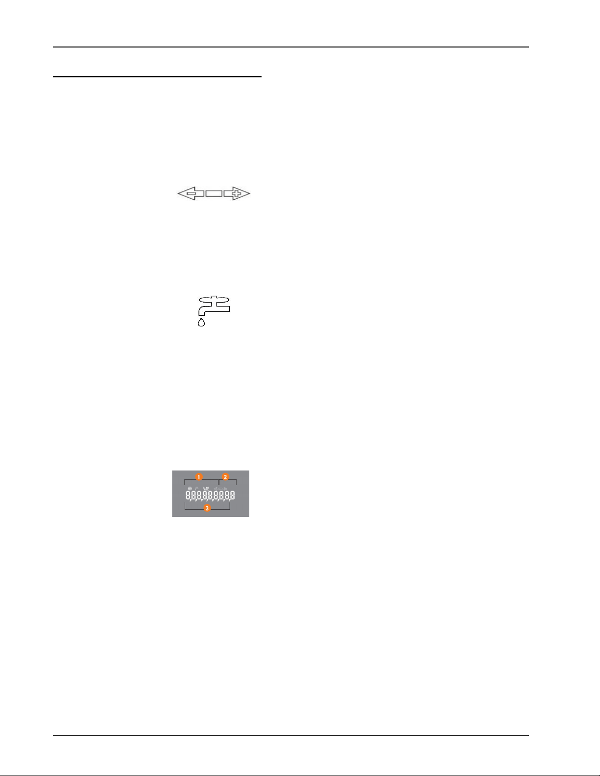
How to Read
It is important to become familiar with the information available from
the meter. To identify this information the following icons and displays
are helpful.
Table 2 Icons and Displays
Flow/Leak Indicator shows the direction of flow through the meter:
ON Water in use.
OFF Water not in use.
Flashing Water is running slowly/low flow indica-
tion.
Leak indicator displays a possible leak:
OFF No leak indicated.
Flashing Intermittent leak indicated. Water used
during at least 50 of the 96 15-minute
intervals during the previous 24-hour
period.
Continuous
ON
Continuous leak indicated. Water used
during all 96 15-minute intervals during
the previous 24-hour period.
Nine-digit LCD displays the meter reading in billing units of measure.
The number is shown in odometer style, reading left to right.
1 First four digits - Typical billing digits.
2 Last three digits - Testing units used for meter testing
3 Fifth and sixth reading digits - Reading units
Activating and Reading the E-Coder)R900i
8 Enhanced E-Coder)R900iInstallation and Maintenance Guide
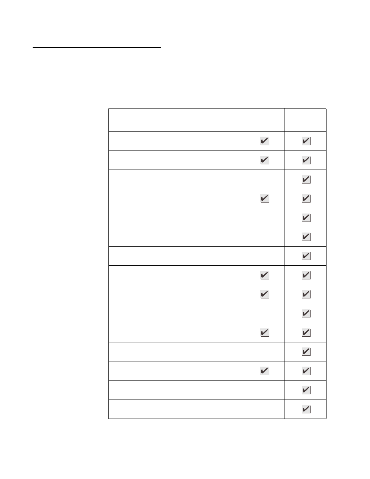
Common Causes of Leaks
If the leak indicator is flashing or continuously on, the E-Coder)R900iis
indicating that a possible leak can exist. Leaks can result from various
circumstances. To better help you identify a possible leak, the following
table contains some common causes of leak problems.
Table 3 Possible Leaks
Possible Cause of Leak Intermittent
Leak
Continuous
Leak
Outside faucet, garden or sprinkler system leaking
Toilet valve not sealed properly
Toilet running
Faucet in kitchen or bathrooms leaking
Ice maker leaking
Soaker hose in use
Leak between the water meter and the house
Washing machine leaking
Dishwasher leaking
Hot water heater leaking
Watering yard for more than eight hours
Continuous pet feeder
Water-cooled air conditioner or heat pump
Filling a swimming pool
Any continuous use of water for 24 hours
Other manuals for E-CODER R900i
1
Table of contents
Other Neptune Industrial Equipment manuals

Popular Industrial Equipment manuals by other brands


Karibu
Karibu 62954 Assembly and operating instructions

JMA Wireless
JMA Wireless Weather Protection System WPS-DM-14S installation instructions

ABB
ABB HT843539 Operation manual

Eastern Energy
Eastern Energy DuraSite 3000 user guide

Bradley
Bradley S19-324D2 installation manual

Titan
Titan PRO-FEED 350 Installation, Maintenance, and Parts Manual