TruSteel AV30 User manual

Copyright © 2020 by TruSteel LLC. All Rights Reserved.
AV30 PRE-INSTALLATION
REQUIREMENTS
AV30 Pre-Installation Requirements
Version: 3.0

AV30 PRE-INSTALLATION REQUIREMENTS | AV30 Pre-Installati on Requirements | v. 3.0
2 / 37
Table of contents
INTRODUCTION ................................................................................................ 3
AUTOVAP30 IMAGES ..................................................................................... 3
STAGE1: RECIEVE EQUIPMENT .......................................................................... 6
CHECKLISTS ................................................................................................. 6
EQUIPMENT MANIFEST .................................................................................. 7
STAGE 2: PLACE EQUIPMENT ............................................................................ 9
FACILITY LAYOUT ........................................................................................ 9
AV30 FLOW DIAGRAM ................................................................................. 10
STAGE 3: INSTALL ANCILLARY ........................................................................ 11
WATER HEATER INSTALLATION ................................................................. 12
WATER HEATER MANIFOLD ..................................................................... 14
CHILLER INSTALLATION .............................................................................. 15
VACUUM PUMP INSTALLATION .................................................................... 17
STAGE 4: CONTROL PANEL WIRING ................................................................. 18
AutoVap30 System Startup ............................................................................ 18
Tools Needed .......................................................................................... 18
Check for loose connections ...................................................................... 18
Measure terminal resistance of the 3 motors (inside the PLC cabinet) ............. 18
Checking Voltage in PLC Cabinet ................................................................ 19
Powering on the Human Machine Interface (HMI) ........................................ 19
Contact Aqua Sierra .................................................................................. 20
STAGE 5: ASSEMBLE AV30 ............................................................................... 20
STAGE 6: PRIME WATER HEATER & CHILLER .................................................... 20
CHILLER FILLING & STARTUP ....................................................................... 21
System requirements ................................................................................ 21
Fill the Chiller .......................................................................................... 21
Troubleshooting ....................................................................................... 22
Alarm Reset Procedure ......................................................................... 22
b1AC Set Point .................................................................................... 23
ALc1 ALARM ON START-UP .................................................................. 24
Contact MTA ........................................................................................ 24
FILL & START WATER HEATING SYSTEM ...................................................... 24
Prepare Equipment ................................................................................... 26
Prepare To Fill PreHeater (Use Port #1) ...................................................... 26
Prepare To Fill Evaporator (Use Port #2) .................................................... 27
Allow Pressure To Rise In System .............................................................. 29
Power On Heater and Recirculating Pump and check system for leaks ............ 29
Adjust Pressure On System (To compensate for heat expansion) ................... 31
Contact Hubbell Support ........................................................................... 31
STAGE 7: VACUUM TEST AV30 ........................................................................ 31
STAGE 8: CLEAN SOLVENT RUN (VIDEO CALL WITH TRUSTEEL) ........................ 32
STAGE 9: TRUSTEEL TRAINING & IQ/OQ .......................................................... 33
APPENDIX ....................................................................................................... 33
REQUIRED COMMODITIES ........................................................................... 33
AV30 REQUIREMENT CHECKLIST .................................................................. 34
CONTACTS ................................................................................................. 37

AV30 PRE-INSTALLATION REQUIREMENTS | AV30 Pre-Installati on Requirements | v. 3.0
3 / 37
INTRODUCTION
Congratulations on your TruSteel equipment purchase! We here at TruSteel are sure you're
going to be impressed at how efficient the the AutoVap recovers your solvent and how EASY
the system is to use.
But, before your AutoVap30 can be installed and run at maximum efficiency, we have to be
sure that your facility is properly set up with all the equipment TruSteel provides you with.
By following the requirements throughout this checklist, you can be sure you will have a quick,
easy install and your AutoVap system will run great for years to come. Setting the stage
properly the first time will save you valuable time and money in the future.
Please take the time to carefully review this manual and refer to it throughout your AutoVap
pre-Installation process.
It is suggested, but not required, to place all ancillary equipment (water heater, chiller, vacuum
pump, PLC) outside of your C1D2 solvent recovery lab.
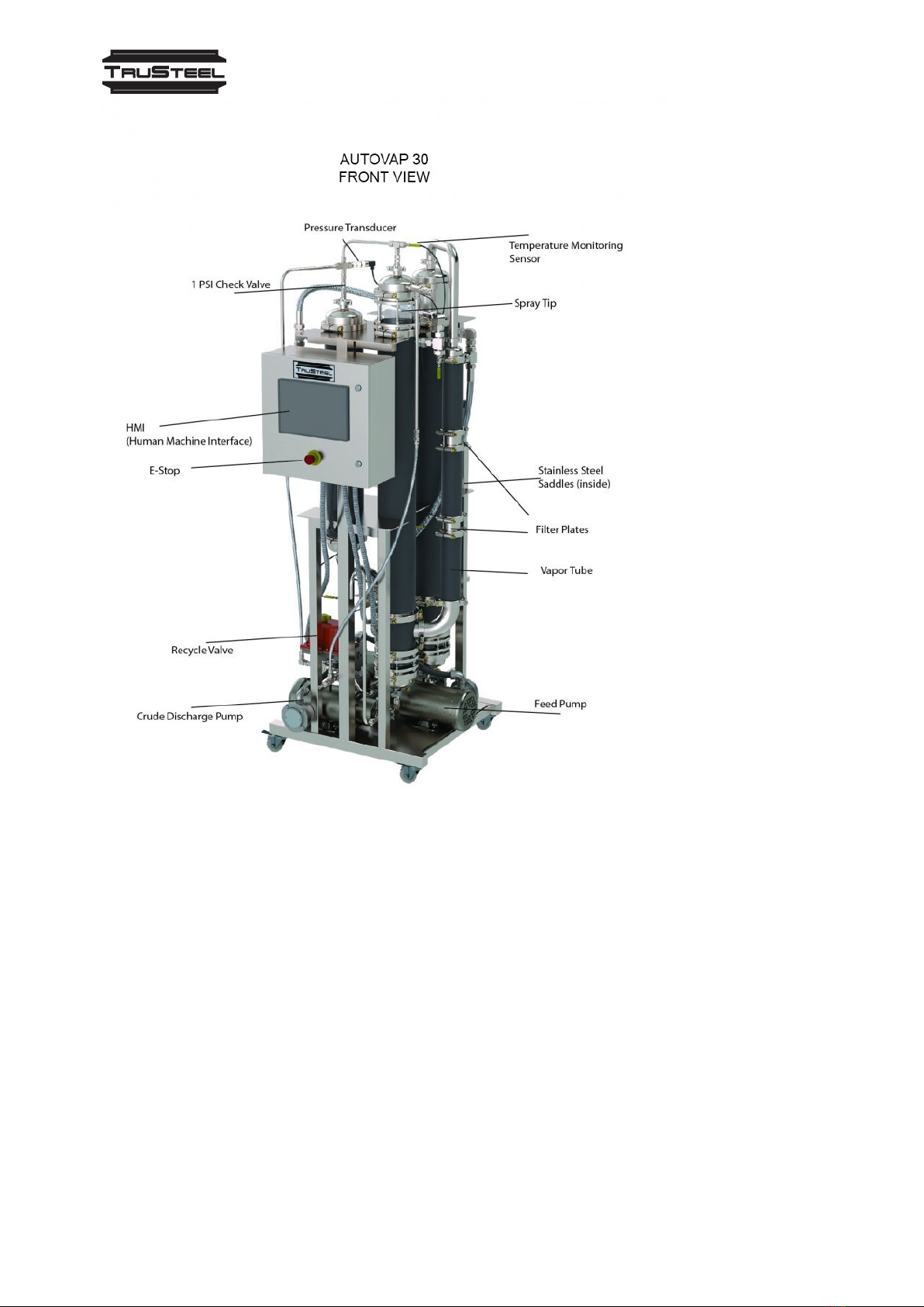
AUTOVAP30 IMAGES
The AV30 is the most efficient solvent recovery system when comparing throughput to
footprint.
With built in fail safes, alarms, data logging, and remote access, the AV30 stands alone as the
leader in the industry.
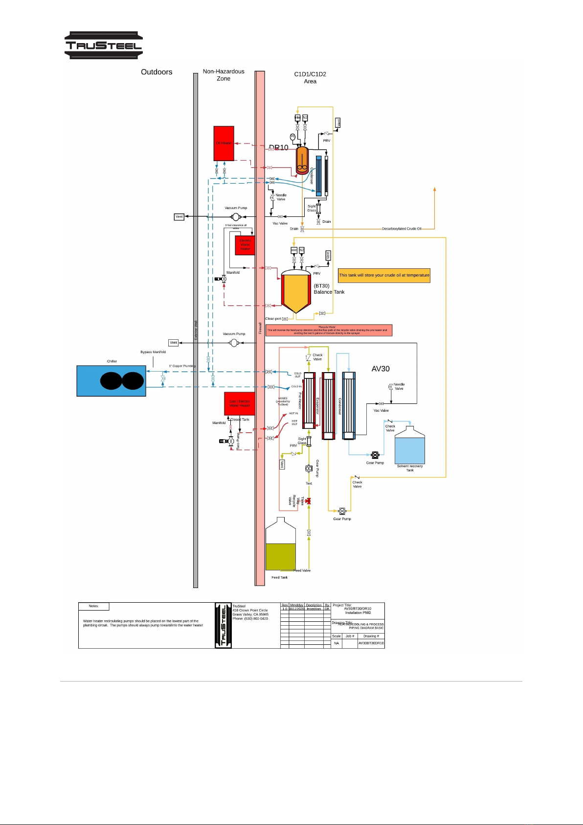
How the AutoVap30 Works
The AutoVap30 works by pumping your tincture up through a preheater before being
atomized through a sprayer. The material than falls through a heated, jacketed exchanger
where the solvent evaporates, and is "pulled" by vacuum into the condenser exchanger
which is cooled from a chiller.
The "crude" material is automatically discharge through a pump and the solvent is re-
condensed and automatically discharge through the solvent discharge pump.
The AutoVap30 has a easy to use cleaning cycle to ensure the longevity of your
AutoVap30 system.
AV30 PRE-INSTALLATION REQUIREMENTS | AV30 Pre-Installati on Requirements | v. 3.0
4 / 37
AV30 PRE-INSTALLATION REQUIREMENTS | AV30 Pre-Installati on Requirements | v. 3.0
5 / 37
AV30 PRE-INSTALLATION REQUIREMENTS | AV30 Pre-Installati on Requirements | v. 3.0
6 / 37
STAGE1: RECIEVE EQUIPMENT
CHECKLISTS
Use the following checklists to keep track of your projects progress. Please print each of
the following checklists for your records.

AV30 PRE-INSTALLATION REQUIREMENTS | AV30 Pre-Installati on Requirements | v. 3.0
7 / 37
EQUIPMENT MANIFEST
Use this checklist as a manifest to ensure all equipment is delivered and on site.
Chiller
Your chiller will most likely be shipping directly from the manufacturer via LTL freight.
TruSteel will provide tracking when available.
Please check the delivered chiller for damage before receiving.
Chiller Model #:
Chiller Serial #:
☐ Chiller Arrived With No Damage
☐ Expansion Tank
☐ Remote Control
Water Heater
The heater unit will be delivered directly from the manufacturer. Please be aware that
the heater will take at least 2 weeks to be manufactured.
Tracking will be provided when available.
Heater Model #:
Heater Serial #:
☐ Electric Water Heater Arrived
Manifold Package
The manifold package will be shipped directly from TruSteel. It will
include: VFD [Variable Frequency Drives], Taco Recirculating Water Pump, Chiller Bypass
Manifold, Water Heater Manifold.
Note: If we determined are using your own chiller, or heater, we may not need to send
this package.
☐ Heater Manifold Pieces: Pressure Release/Gauge Section (Medium), Fill Port/Filter
Screen Section (Big)
☐ Expansion Tank (Blue Tank)

AV30 PRE-INSTALLATION REQUIREMENTS | AV30 Pre-Installati on Requirements | v. 3.0
8 / 37
☐ Taco Pump (Green Recirculating Pump) and Flange Set
☐ Chiller Bypass Manifold
☐ Taco Pump Ball Valve (Small)
☐ (4) Hose Barbs
☐ (4) Sharkbite Valves
Inline Pump
Model #:
Inline Pump
Serial #:
Vacuum Pump
Vacuum Pump
Model #:
Vacuum Pump
Serial #:
☐ Vacuum Pump Received
AutoVap30 and Control Panel (2 Separate Crates)
Control Panel
Model #:
Control Panel
Serial #:
☐ AutoVap30 & Control Panel Received
AV30 PRE-INSTALLATION REQUIREMENTS | AV30 Pre-Installati on Requirements | v. 3.0
9 / 37
STAGE 2: PLACE EQUIPMENT
Important things to consider when placing your equipment:
1) The chiller exhausts a large amount of hot air. We highly suggest placing the chiller
outside of your facility, either on a concrete slab or on the roof. If this is not possible,
please confirm with the chiller manufacturer if your facility has adequate air flow and
space for the chiller to run inside. Placing an HVAC exhaust system on the chiller is also
an option for indoor use.
2) The water heater is a crucial part of your AV30 system. It is important to get
maximum efficiency out of your water heater. The flow rate of the water heater will be a
determining factor of the efficiency of the heat as the AV30 recovers solvent.
To ensure maximum flow rate, the water heater should be placed as close to the AV30 as
possible and the plumbing should have a few 90 degree turns as possible. The plumbing
run should have as little vertical differential as well.
3) The recirculating water pump, which is part of the water heater manifold, is what
essentially powers on the water heater each day. It is advised to have your electrician
connect this pump to a wall switch that is easily accessible by your operators.
4) The vacuum pump, similar to the recirculating pump, should be placed on it's own wall
switch for convenience. Note: place on a separate wall switch from the recirculating
pump.
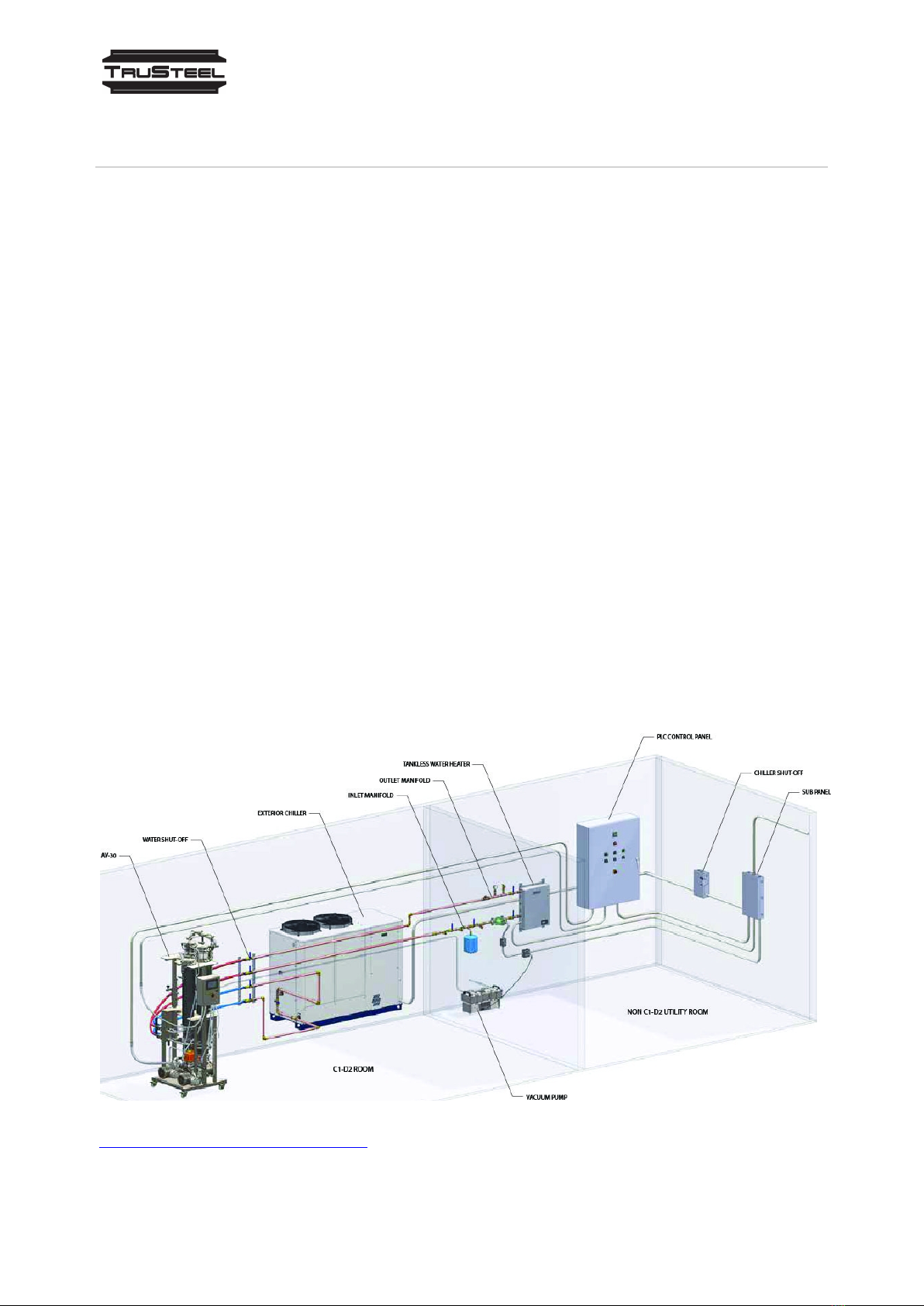
FACILITY LAYOUT
CLICK HERE FOR PDF VERSION

AV30 PRE-INSTALLATION REQUIREMENTS | AV30 Pre-Installati on Requirements | v. 3.0
10 / 37
This layout diagram is only a suggestion to how a facility could lay out. The customer is
responsible for consulting with their local fire marshal in order to ensure code
compliance. TruSteel is not responsible for setting up the customer facility in order to
comply with any local codes.
The AutoVap30 is C1D2 compliant. The ancillary, however, is not and should be placed
outside of the solvent recovery room.
The chiller unit should be placed in a well ventilated area, preferably outside of the
facility in the open air (on a concrete slab or on the roof).
The chiller should be within 50 feet of the AutoVap30 unit in order to be most efficient.
The water heater should be placed outside of the C1D2 room. The electric water heater
does not require ventilation, while the gas heater will require proper ventilation. The
water heater, ideally, should be within 30 feet of the AutoVap30 for full efficiency.
The vacuum pump, AutoVap30 PLC, and heater manifold inline pump should all be
outside of the C1D2 solvent recovery room.
AV30 FLOW DIAGRAM
Click here for PDF Version of AV30 Flow Diagram
AV30 PRE-INSTALLATION REQUIREMENTS | AV30 Pre-Installati on Requirements | v. 3.0
11 / 37
STAGE 3: INSTALL ANCILLARY
This section provides important information for each piece of equipment that needs to
be installed. Most equipment will have manuals with them when they arrive, but we
have also provided links to the manuals and, in some cases, some extra installation
materials.

AV30 PRE-INSTALLATION REQUIREMENTS | AV30 Pre-Installati on Requirements | v. 3.0
12 / 37
WATER HEATER INSTALLATION
[Picture Caption: Hubbell HX Electric Water Heater (left), Hubbell NX Gas Water
Heater (right)]
ELECTRIC WATER HEATER: Model HX
Tankless Electric Water Heater
Available in 33-36 KW Three Phase Voltages
The Hubbell model HX Tankless electric water heater is a highly reliable and easily
maintained heater designed for operation in a commercial or industrial application.
The Hubbell HX Tankless heater is compact, extremely efficient, takes up minimal
space and reduces operating costs.
Electric Water Heater Technical Documents
·Model HX / TX Brochure PDF
·Model HX / TX Written Spec PDF
·Model HX / TX O&M Manual PDF
GAS WATER HEATER: Model NX300
Tankless Electric Water Heater
Available in 33-36 KW Three Phase Voltages
The Hubbell model HX Tankless electric water heater is a highly reliable and easily
maintained heater designed for operation in a commercial or industrial application. The
Hubbell HX Tankless heater is compact, extremely efficient, takes up minimal space and
reduces operating costs.
Important Note!! Gas Heater will require an external flow switch AND an strap-on
aquastat. Your plumber can provide these or you can purchase them below.

AV30 PRE-INSTALLATION REQUIREMENTS | AV30 Pre-Installati on Requirements | v. 3.0
13 / 37
Where to Purchase:
1) Flow Switch
2) High or Low Limit & Circulator Strap-On Aquastat
Gas Water Heater Technical Documents
·Hubbell Model NX Brochure PDF
·Hubbell NX O&M PDF
·Hubbell NX300 Submittal Sheet PDF
·Model NX300 Spec PDF
Water Heater Requirements
See Water Heater Requirements (Section AV30 REQUIREMENTS CHECKLIST)
Link To Helpful Video
Important Information
1. For C1D2 compliance, the water heater should be placed OUTSIDE of the room that
the AutoVap will be running in. The heater is NOT C1D2. Place the heater on
the outside of the wall from the AutoVap with the manifold attached, and then plumb
your copper (NO FLUX), or PEX, through the wall, into the room.
Important Note: The closer your heater, and the more direct the plumbing run is, the
more efficient your heater will work with the AutoVap. The flow rate of your closed loop
to the AutoVap is VERY important. A short, straight path will ensure a higher flow rate.
2. The heater manifold, provided by TruSteel, will be installed directly into the water
heater. To Install Manifold:
a. Remove plastic pex fitting inside of the Sharkbite fitting on the water heater
inlet and outlet.
b. Insert straight copper end into Sharkbite fitting.
c. Make sure manifold is securely mounted with unistrut
3. The copper (NO FLUX) will be run to the shark bite side of the ball valves provided.
The ball valves are mounted on a unistrut.
4. The TACO inline water pump will be used to recirculate the water in the system. This
will essentially power up the heater since it needs flow to run.
We suggest putting the Taco pump on wall switch, rather than a plug outlet, for
convenience. This will essentially be your on/off switch for your heater since the flow
powers up the heater.
Be sure the Taco pump is facing the correct direction (the control panel should be facing

AV30 PRE-INSTALLATION REQUIREMENTS | AV30 Pre-Installati on Requirements | v. 3.0
14 / 37
out from the wall) and the flow arrow should be going toward the water heater.
Commodities Needed By Customer
Needed to prime the system and for maintenance
1. You will need a sump pump (minimum 25 ft. head pressure) to prime the system.
Click Here to Purchase a Sump Pump (or see example)- Amazon.com
2. Short piece of garden hose, with hose fittings to connect sump pump to manifold
intake.
Click Here to Purchase (or see example) - Amazon.com
3. Distilled Water (about 20 gallons): You'll need around 50-60 gallons total, including the
chiller requirements.
4. ~35 gallon reservoir
Click Here to Purchase a Reservoir (or see example)-Amazon.com
Contact Hubbell Heaters
Call: (800) 647-3165
Or: (203) 378-2659
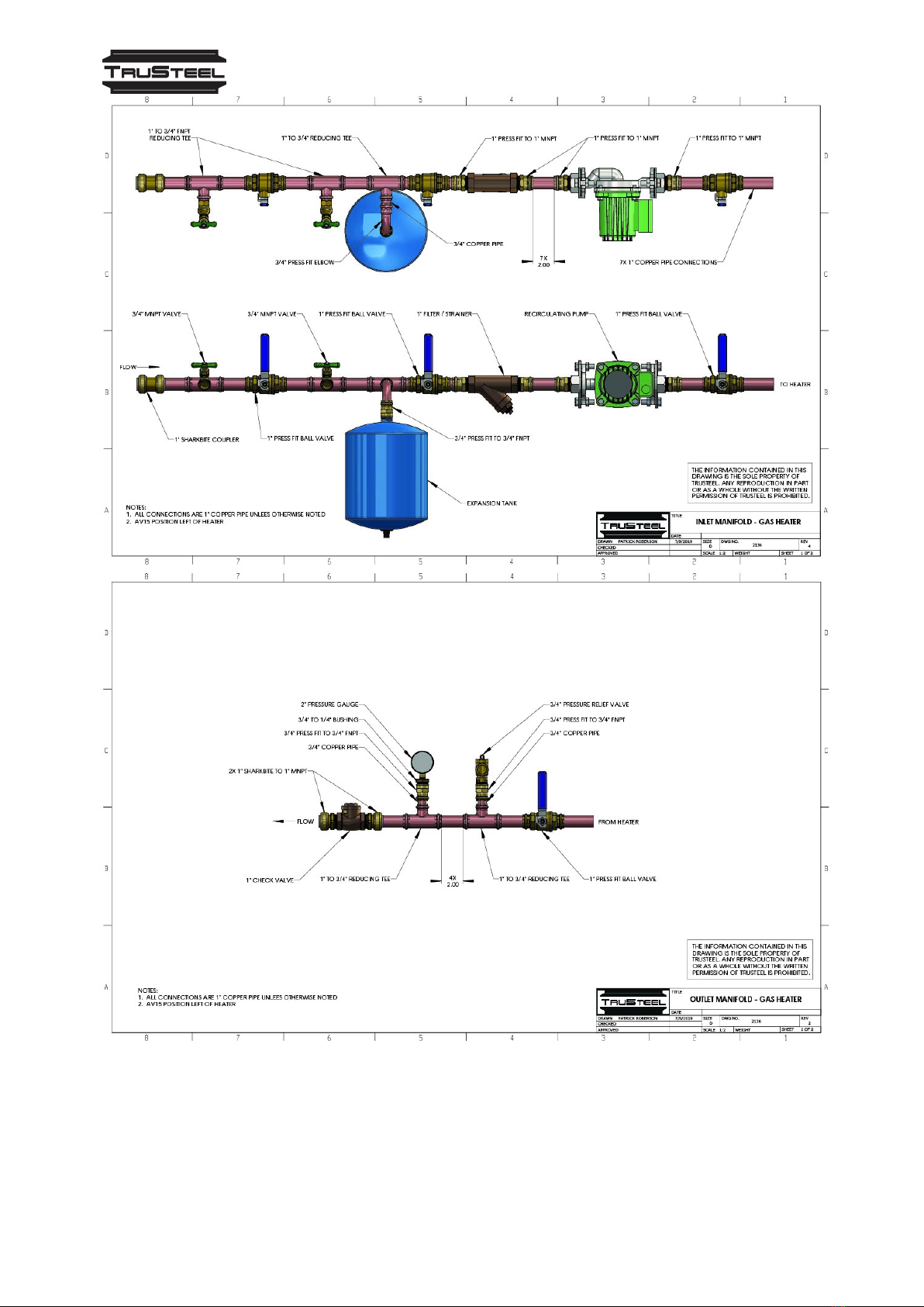
WATER HEATER MANIFOLD
The TACO Inline Recirculating Pump is part of the heater manifold that is supplied by TruSteel.
It is highly suggested to connect the power of the pump to a wall switch. Place the wall switch
in a convenient locati on for your facility operators. This pump essentially powers on the water
heater by supplying fl ow.
RECIRCULATING PUMP
MODEL ELECTRICAL HORSEPOWER UNIT DIMENSIONS
VR3452-HY1-
FC1A00 115V 1Ø 2.5A 1/100 to 1/4 See Submittal Data
Information
CLICK HERE FOR PDF VERSION
AV30 PRE-INSTALLATION REQUIREMENTS | AV30 Pre-Installati on Requirements | v. 3.0
15 / 37
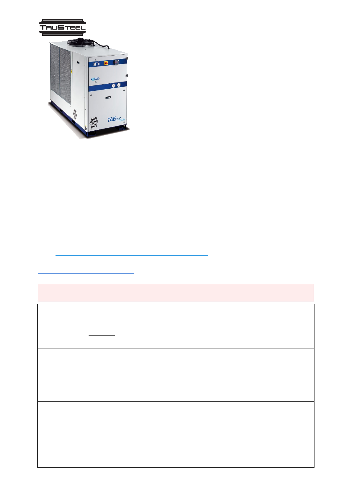
CHILLER INSTALLATION
AV30 PRE-INSTALLATION REQUIREMENTS | AV30 Pre-Installati on Requirements | v. 3.0
16 / 37
MODEL TaeEvoTECH
Air Cooled Chillers
The TAEevo range of air-cooled chillers are a packaged unit
designed for industrial applicati ons. They are supplied with
hermetic scroll or reciprocati ng compressors and an
innovative finned pack evaporation inside the storage tank.
Technical Documents
Note: The installation instructions should be in the upper cabinet of the unit.
·Installation Instructions (PDF) [2 MB]
·Alarm Resets and Other Important Info (PDF) [5 MB]
SEE CHILLER REQUIREMENTS
Important Information
1. The chiller should be placed OUTSIDE of the facility, either on a roof, or a concrete
slab. If placed inside, proper HVAC ventilation is required. The
chiller CANNOT operate in a closed space; the unit dissipates a lot of heat. Please
contact MTA (Manufacturer) if you have any doubt of chiller placement.
2. The bypass manifold, provided by TruSteel, should be properly installed by a
plumber. Use plumbers dope AND plumbers tape.
3. The copper plumbing(Crimped or Push Connect – NO FLUX) will be run to the shark
bite side of the ball valves provided. The ball valves are mounted on a unistrut.
4. The chiller requires a propylene glycol/water mixture. Please refer to the
Installation Instructions to verify how much propolyene glycol your unit will require.
(Ratio is climate dependant) Link to Purchase
5. Please note that the chiller IS NOT powered by the AutoVap30 Control Panel. The
chiller is not controlled by the AutoVap30. The AutoVap30 only monitors, not
AV30 PRE-INSTALLATION REQUIREMENTS | AV30 Pre-Installati on Requirements | v. 3.0
17 / 37
controls, the temperatures supplied by the chiller. If the chiller is not supplying
enough cool fluid, the AutoVap30 sensors will alarm you.
6. Don't forget to wire up your remote control for the chiller. The remote will make it
very convenient to put the chiller into STANDBY mode when not in use.
Helpful Information
Link To Purchase Propylene Glycol
Contact MTA for Installation Inquiries
West Coast Customer Service
Joel Gordon (206) 851-8456
jgordon@mta-usa.com
East Coast Customer Service
Jim Kirchoff (248) 880-4025
jkirchoff@mta-usa.com
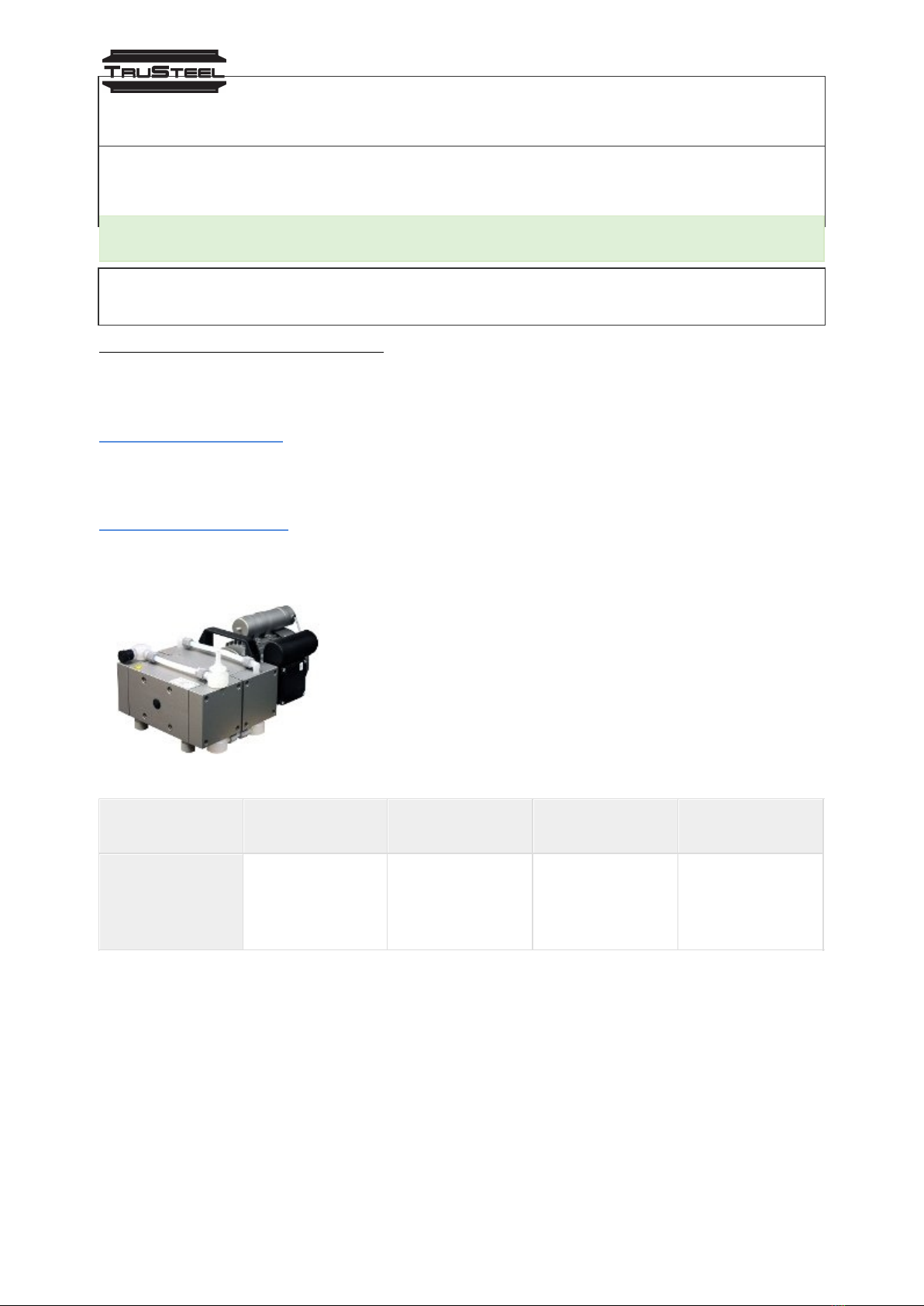
VACUUM PUMP INSTALLATION
Model Welch 2052
Welch 2052 2.3 cfm Full Chemical-Resistant 4-Head
Diaphragm Pump
The original Welch 2052 is a full chemical-resistant (not like
its cheaper version), 4-head, oil-free dry diaphragm vacuum
pump with all-PTFE contact surfaces and deep vacuum
capability. Oil-Free, portable, full chemical-resistant, means
less maintenance and no more frequent and costly oil
change, or cross contaminati on.
MODEL ELECTRICAL RE
QUIREMENTS PUMPING RATE UNIT DIMENSIO
NS WEIGHT
WELCH 2052
110V 60Hz
single phase
0.53 HP, 390
watts
2.3 cfm 9 × 15 × 7
inches 40.3 Lb
Vacuum pump is connected to AutoVap with a braided silicone hose (provided by TruSteel)
The customer may choose to run a discharge line from the vacuum pump in the event that
solvent gets “pulled” through the vacuum.
TruSteel suggests putting the vacuum pump on a wall switch to make easy on/off for facility
operators.
Technical Document
·Welch 2052 Operation Manual

AV30 PRE-INSTALLATION REQUIREMENTS | AV30 Pre-Installati on Requirements | v. 3.0
18 / 37
SEE VACUUM PUMP REQUIREMENTS
STAGE 4: CONTROL PANEL WIRING
Technical Documents
·Technical Wiring Diagram
Helpful Links & Important Information
Purchase Link For K-Type Wire
Your electricianshould provide youwithall the wiring and conduit.
ContactAqua Sierra for Support, Call: 530.823.3241
SEE CONTROLPANELREQUIREMENTS CHECKLIST
Link To Help Video
AutoVap30 System Startup
WARNING! DO NOT TURN ANY POWER ON BEFORE CHECKING
VOLTAGE AND MEASURING TERMINAL RESISTANCE
Tools Needed
·Volt/Ohm multimeter
·Small terminal block screwdriver
·Standard flat head screwdriver
·½” wrench
·⅝” wrench and/or ⅝” ratchet and socket
·⅞” wrench
·13/16” wrench
·Wire strippers
·Crescent wrench
Check for loose connections
Start by checking the wire connections made inside the Operator Panel(HMI) and in the PLC cabinet.
Pull softly but firmly on each of the wires for the 24v inputs and for VFD motor leads.
Reconnect any loose wires.
Measure terminal resistance of the 3 motors (inside the PLC cabinet)
Using a multimeter, measure the resistance(ohms) of the terminals to make sure that the motors are
landed correctly in the junction box.

AV30 PRE-INSTALLATION REQUIREMENTS | AV30 Pre-Installati on Requirements | v. 3.0
19 / 37
If all three resistance readings for each pump are relatively close then the motor wiring in the
junction box is most likely correct.
Test each pump individually and as follows:
Using your multimeter put one test lead on U and the other on V. Note the resistance. Then leave the
lead on U and put the other lead on W. Note the resistance. Lastly, leave the lead on W and put the
other lead on V. Note the resistance. Do this for all 3 pumps. (See resistance ranges below for
reference)
**If one of the three readings has a difference of more than 0.5 ohms. Check motor wiring at junction
box.
Resistance Ranges:
Residue Pump
U1A-V1A = 8-10 ohms
V1A-W1A = 8-10 ohms
W1A-U1A = 8-10 ohms
Ethanol Pump
U2B-V2B = 8-10 ohms
V2B-W2B = 8-10 ohms
W2B-U2B = 8-10 ohms
Feed Pump
U3C-V3C = 8-10 ohms
V3C-W3C = 8-10 ohms
W3C-U3C = 8-10 ohms
Checking Voltage in PLC Cabinet
***WARNING! DO NOT POWER ON THE MAIN BREAKER UNTIL YOU VERIFY THE CORRECT VOLTAGE
(208-240V)
Measure (A phase-B phase) leg-to-leg by testing the two wires landed in the top side of Main
Breaker(CB1) with your multimeter. Make sure you have 208-230v. If you don't have the proper
voltage, first make sure the breaker or disconnect for PLC is powered “ON”. If you still don't have the
correct voltage(208-230V) STOP and get an electrician for assistance. DO NOT CONTINUE UNTIL YOU
RESOLVE THE ISSUE AS YOU COULD POSSIBLY DAMAGE THE PLC.
After confirming the correct voltage, check that all Circuit Breakers in the PLC are set to “OFF” or
Green(safe).
Make sure all circuit breakers are set to “OFF/GREEN”. Once all circuit breakers are off, turn on Main
Breaker(CB1).
Test the 120V wiring in the PLC cabinet with your multimeter by touching one lead to the Neutral and
the other lead to the top side of Circuit Breaker # 5 (CB5). It is located in the top left side of the PLC
cabinet.
If 120v is present you may turn on all circuit breakers and can now power on the HMI. If 120V is not
present, STOP and call Aqua Sierra.
Powering on the Human Machine Interface (HMI)
AV30 PRE-INSTALLATION REQUIREMENTS | AV30 Pre-Installati on Requirements | v. 3.0
20 / 37
Make sure the jumper wire in the PLC is removed. Itʼs landed in terminals +24Q and +24R.
For the HMI to power up, terminals +24O and -24V must be landed in both the HMI and PLC panels.
Pull out the 2 the E-Stops to start the AutoVap. One is on the PLC cabinet and one is on the HMI.
If HMI powers up but does not display any data this means that PLC is not communicating with the
HMI. Check the ethernet cable connections and re-crimp each end if necessary.
Contact Aqua Sierra
For questions/concerns/troubleshooting the PLC or HMI, please call Aqua Sierra (located
in Pacific Standard Time)
Call: 530.823.3241
STAGE 5: ASSEMBLE AV30
Link to Video Online
STAGE 6: PRIME WATER HEATER & CHILLER
Before proceeding to fill the water heater and chiller, you must have the RED and BLUE
hoses connected to the AV30.
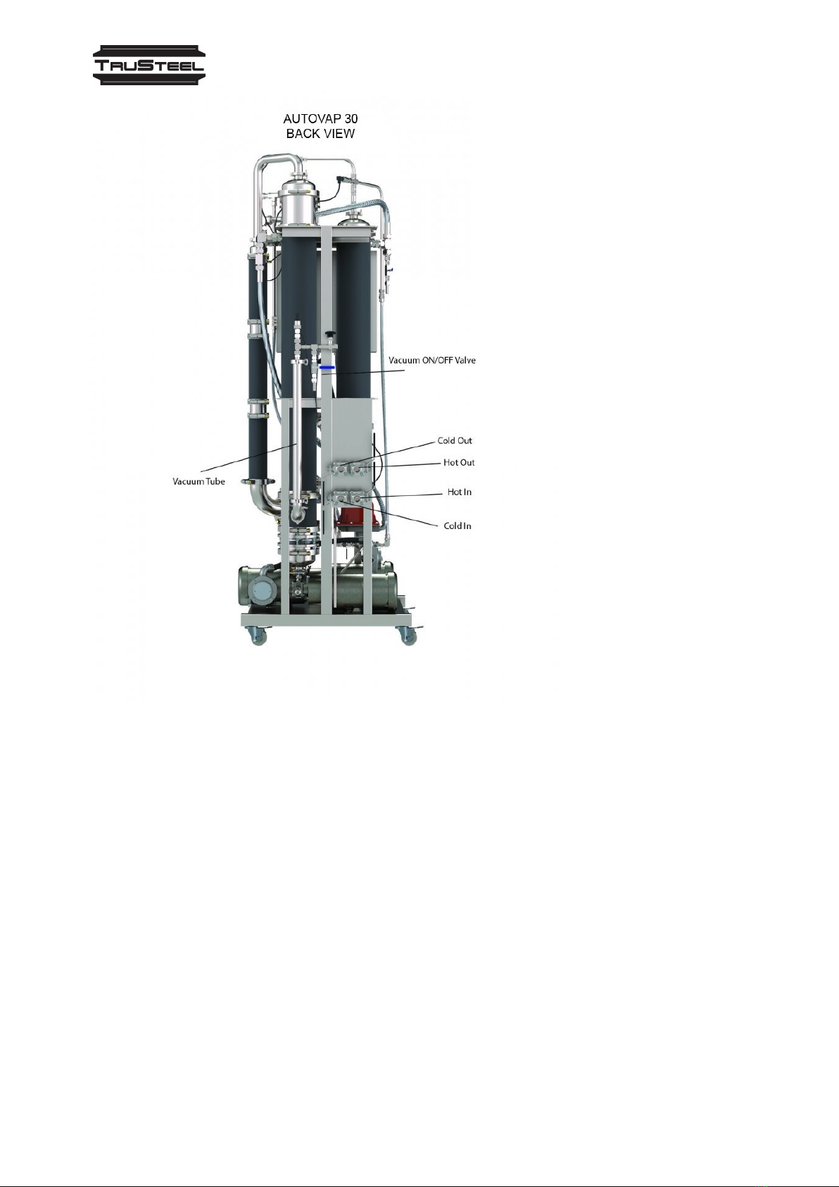
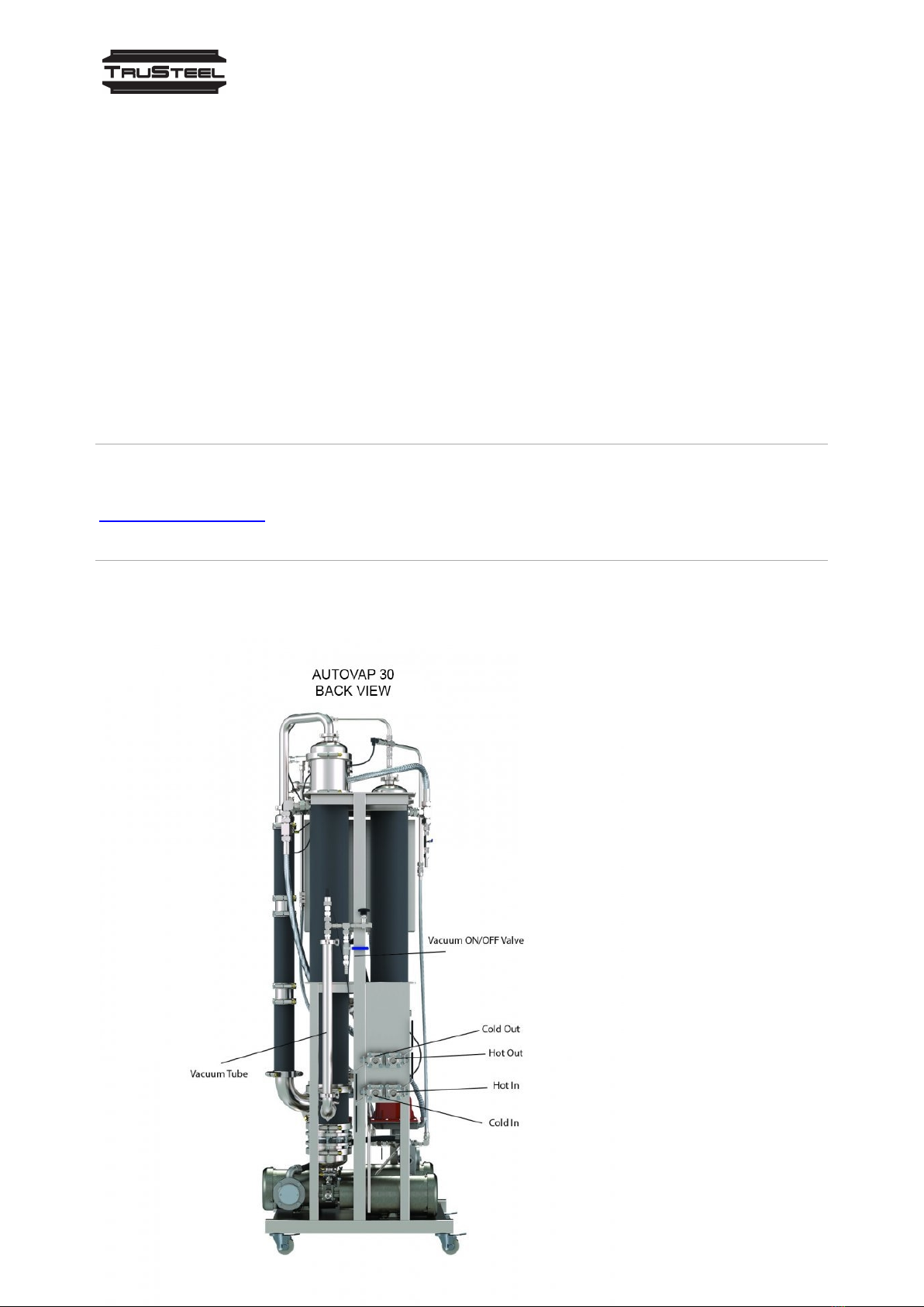
In the image of the
AV30, locate the Cold
Out and Cold In. These
will be the BLUE hose
connections to/from
the chiller.
Cold In: From the chiller
Cold Out: Back to the
chiller
In the image of the
AV30, locate the Hot
Out and Hot In. These
will be the RED hose
connections to/from
the water heater.
Hot In: From the water
heater
Hot Out: Back to the
water heater
Table of contents
Other TruSteel Industrial Equipment manuals


