Toray NHP210 Series User manual

NIRE-170-1-6
Submerged Membrane Module
for MBR
TORAY “MEMBRAY”
“NHP210 Series”
Instruction Manual
Toray Industries, Inc.
Water Treatment Division
1-1, Nihonbashi-muromachi 2-chome, Chuo-ku, Tokyo 103-8666 Japan
Tel +81-3-3245-4542
Fax +81-3-3245-4913
URL www.toraywater.com
Published: August 2020

NIRE-170-1-6
Content
I. INTRODUCTION..................................................................................................................... 1
1. Features of MBR ................................................................................................................... 1
2. Outline of “NHP210 Series”................................................................................................... 2
II. FOR SAFE OPERATION OF “NHP210 SERIES” .................................................................. 5
1. Unpacking and Installation.................................................................................................... 5
2. Operation and Maintenance.................................................................................................. 6
3. Chemical Cleaning of Element.............................................................................................. 7
III. SPECIFICATIONS AND PERFORMANCE OF “NHP210 SERIES” ...................................... 9
1. Specifications of Element...................................................................................................... 9
2. Specifications of Filtrate Tube Assembly.............................................................................. 9
3. Specifications and Performance of “NHP210 Series” Module.............................................. 9
IV. MEMBRANE FILTRATION PROCESS DESIGN FOR “NHP210 SERIES” ......................... 12
1. Standard Time Chart........................................................................................................... 12
2. Flow Diagram of Membrane Filtration................................................................................. 13
3. Layout of “NHP210 Series” Modules in Membrane Tank................................................... 18
4. Piping................................................................................................................................... 21
V. INSTALLATION OF “NHP210 SERIES”............................................................................... 24
1. Preparatory Procedure........................................................................................................ 24
2. Unloading/lifting Products.................................................................................................... 24
3. Checking Products .............................................................................................................. 25
4. Storage Products................................................................................................................. 25
5. Installation Products............................................................................................................ 26
VI. START OF OPERATION...................................................................................................... 30
1. Clean Water Operation........................................................................................................ 30
2. Seeding Sludge Injection..................................................................................................... 31
3. Actual Filtration Operation................................................................................................... 32
VII. OPERATION CONTROL...................................................................................................... 33
1. Standard Operating Conditions........................................................................................... 33
2. Operating Parameters......................................................................................................... 35
3. Basic Control Philosophy .................................................................................................... 35
4. Daily Inspection................................................................................................................... 37
VIII. MAINTENANCE OF “NHP210 SERIES” .............................................................................. 40
1. Maintenance Items and Maintenance Frequency............................................................... 40
2. Air Diffuser Cleaning............................................................................................................ 41
3. Chemical Cleaning of Element............................................................................................ 43
4. Chemical Agents Available for Chemical Cleaning............................................................. 43
5. Handling of Chemical Agents.............................................................................................. 44
6. Chemical Cleaning Procedure............................................................................................. 47
7. Lifting Procedure ................................................................................................................. 52
NIRE-170-1-6
8. Storage Products after Use................................................................................................. 53
9. Disposing Procedure........................................................................................................... 54
IX. REPLACEMENT PARTS LIST............................................................................................. 55
X. TROUBLESHOOTING.......................................................................................................... 56
XI. APPENDIX............................................................................................................................ 57
Symbols used in this manual
This symbol is used to indicate an imminent hazardous situation
which, if not avoided, will result in serious injury or death.
This symbol is used to indicate a potentially hazardous situation
which, if not avoided, can result in serious injury or death.
This symbol is used to indicate a potentially hazardous situation
which, if not avoided, may result in injury or property damage.
DANGER
!
WARNING
!
CAUTION
!
NIRE-170-1-6
1
I. INTRODUCTION
Toray "MEMBRAY" is the submerged membrane module suitable for the membrane
bioreactor (MBR) that has been developed based on the polymer science and the membrane
fabrication technologies accumulated for a long time in Toray Industries, Inc.
"NHP210 Series" is a new model of "MEMBRAY" equipped with thin membrane elements
having higher packing density, while reliable performance of Toray PVDF membrane has
been kept unchanged. This manual explains MBR's features and describes the specifications
of "NHP210 Series" and its safe operations including installation, operation, maintenance
procedures and peripheral equipment. Operators should thoroughly read this manual to
ensure stable operation.
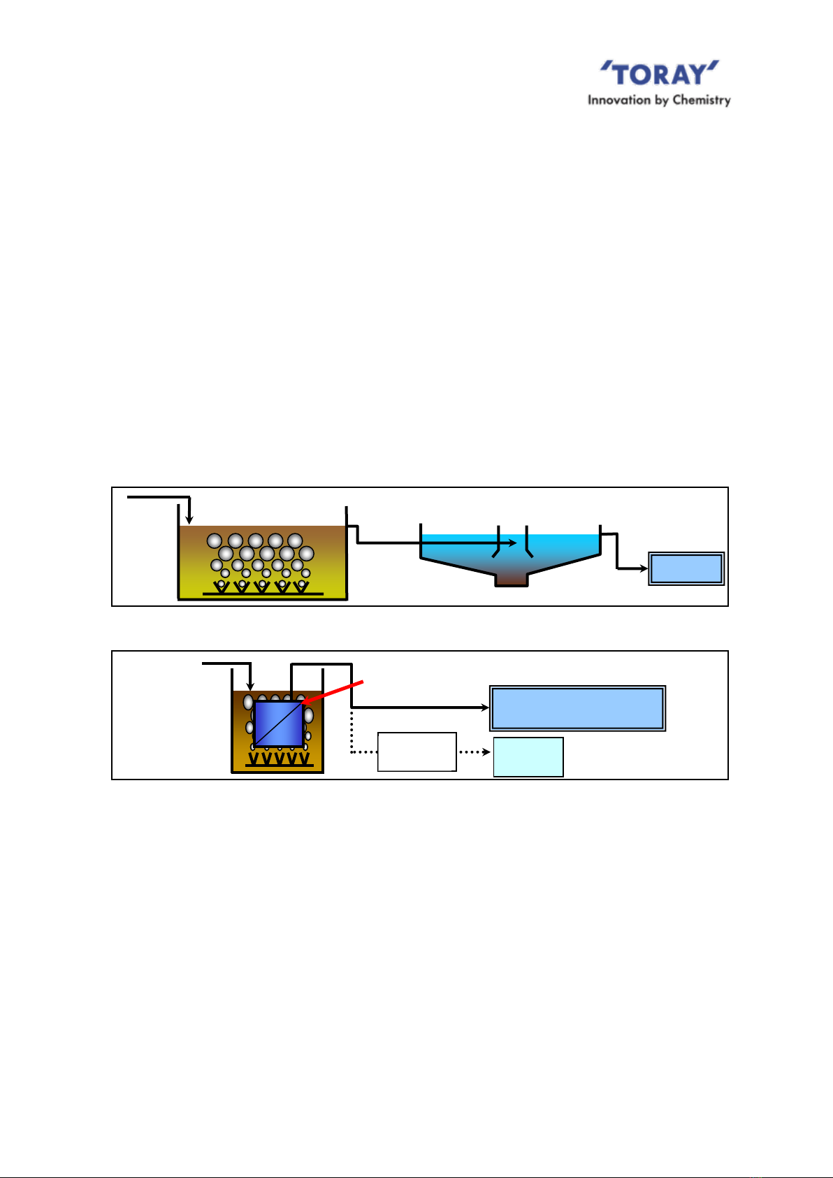
1. Features of MBR
The process flow of the conventional activated sludge system (CAS) and MBR are shown in
Fig.I-1 and Fig.I-2, respectively.
MBR provides the following advantages:
(1) Small Footprint
Unlike CAS, MBR separates sludge within aeration tank using membranes, thus eliminate
the space for preparing sedimentation tank. Also with membrane, MBR can hold higher
concentration of activated sludge in the aeration tank, so its volume can be reduced. As a
result, MBR provides smaller footprint compared to CAS.
(2) High quality of treated water
MBR removes suspended solid (SS) from the sludge liquid with membrane much more
Sedimentation Tank
Waste
water
Aeration Tank
Discharge
Wastewater
Discharge or Reuse
Reuse
RO
membrane
Submerged Membrane
Module
Membrane
Tank
Fig. I-1 CAS Flow
Fig. I-2 MBR Flow

NIRE-170-1-6
2
certainly than conventional sedimentation process. MBR also rejects microorganisms such
as Escherichia coli and Cryptosporidium efficiently.
2. Outline of “NHP210 Series”
“NHP210 Series” is the membrane module composed of the element block and the aeration
block. The element block contains a number of cassettes and in the cassette membrane
elements are stacked at equal clearance, each of which has flat sheet membrane on both
sides. Each element is connected via plastic tube to the filtrated water manifold. The aeration
block consists of coarse-bubble air diffusers to supply scouring air (see Fig.I-3).
This module is used submerged in sludge liquid.
The following shows the features of “NHP210 Series”.
Fig. I-3 Components and appearance of “NHP210-300S”
Nozzle
Filtrate water manifold
Tubes
Module
Frame
Cassette
Element
50 sheets
Element
block
Aeration
block
Coarse
bubble
diffuser
6 pcs
NIRE-170-1-6
3
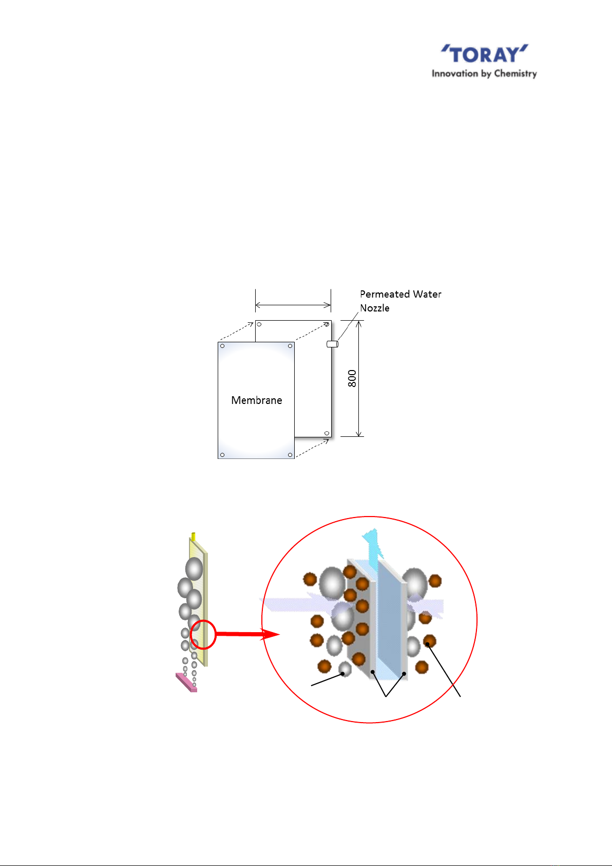
(1) Shape of Element
The membrane element is a flat sheet type as shown in Fig.I-4. At the normal filtration
operation, the sludge accumulated on the membrane surface is cleaned up effectively with
upward water stream generated with the scouring air supplied from the air diffusers installed
at the bottom side (Fig.I-5). This mechanism ensures stable filtration, since the membrane
does not easily admit of sludge adherence to its surface.
In addition, thin membrane element makes it possible to have higher membrane packing
density in the module similar to that of hollow fiber membrane, and also to improve
membrane cleaning efficiency thanks to vibration of elements by scouring air.
Fig. I-4 Structure of Element
Fig. I-5 Filtration Principle of Activated Sludge
Air
diffuser
Element
Filtrated water
Activated sludge particle
Membrane
Air
480

NIRE-170-1-6
4
3.0 micron
Fig. I-6 Membrane Surface
(photo)
Fig. I-7 Pore Size Distribution
(2) Membrane Structure
The flat sheet membrane consists of PVDF (Polyvinylidene Fluoride) functional layer and the
base layer of PET (polyester) non-woven fabric. This structure gives the membrane superior
physical strength and high chemical resistance.
(3) Membrane Pore Size
Numerous small-size pores are distributed evenly over the membrane surface with a sharp
pore-size distribution. This structure gives an outstanding high treated water quality and
excellent water permeability, making the membrane highly resistant to clogging (see Fig.I-6
and Fig.I-7) compared to other membranes. The average pore size is 0.08 micron meter.
Pore size (micron)
東レ
BF014
クボタ
0
0.5
1.0
1.5
0.2
0.4
0.6
0.8
0
Number of pore (1012/m2)
0.08 micron
NIRE-170-1-6
5
II. FOR SAFE OPERATION OF “NHP210 SERIES”
Before using “NHP210 Series”, please thoroughly read this Instruction Manual and follow the
instructions described in this manual, especially the safety precautions shown below. The
details of each precaution are described in the relevant chapter
1. Unpacking and Installation
When lifting “NHP210 Series”, attach chains or slings to the lifting
lugs. Slowly raise the module straight up. Avoid sudden changes in
movement to minimize shaking the module. Never allow
personnel to stand under the “NHP210 Series”during lifting
Use chains or slings rated for the weight being lifted. Check the
condition of each part before lifting. Never lift or operate the
module with worn or damaged parts.
When lifting double-decker module, do not lift upper element
blocks and lower element blocks as one unit. Lift the upper and
lower element block separately.
When installing “NHP210 Series”module, make provisions, in
advance, to access the upper portions of the membrane module
via a scaffold or ladder.. Do not climb on the module structure.
Never step on the air diffuser/manifold. Use protective equipment
to ensure the safety of workers.
Please wear the appropriate personal protective equipment (e.g.
work gloves) in order not to cut hand on the edge of the module
frame.
During transportation, storage and installation, take appropriate
measures to protect "NHP210 Series" or associated components
from damage. Do not put any heavy objects directly on the module.
Store the module in an area that will minimize the potential for
damage from moving equipment like fork lifts etc.
Exposing the “NHP210 Series” and membrane elements to
temperatures above 40 degree C or direct sun light should be
avoided. Exposure to direct sun light/UV radiation will cause the
polypropylene air diffuser/manifold to deteriorate.
Take adequate measures, during the installation process, to
protect the “NHP210 Series” from: sparks emitted from welding
equipment, fusion cutting or grinding.
Protect “NHP210 Series” from freezing at all time.
Avoid pressurizing the filtrate side of "NHP210 Series”.
DANGER
!
DANGER
!
DANGER
!
CAUTION
!
CAUTION
!
CAUTION
!
CAUTION
!
CAUTION
!
DANGER
!
CAUTION
!
NIRE-170-1-6
6
Install the screen with openings of 3.0 mm or under before the
membrane tank. Mesh type screen is recommended. Overflow or
waste carryover must be avoided at all time.
Connect the flanges of air diffuser/manifold to the piping with the
tightening torque of 20 N.m, in order to avoid distortion, leakage or
breakage of the plastic air diffuser/manifold.
Consider piping material and regulate the load to the flange
connection points less than 20 kg per flange, in order to avoid
distortion, leakage or breakage of the plastic air diffuser/manifold. If
the load is higher than the limit above shown, put some supports
on the piping to reduce the load.
2. Operation and Maintenance
Filtrated water is not for potable uses. Do not drink the MBR
filtrate.
Before discharging the treated water to the environment or reusing
it, make sure to analyze its quality and confirm that the water
quality meets the intended purpose.
Do not burn the membranes without appropriate facilities since
harmful Hydrogen fluoride (HF) gas will be generated. When
disposing of the membrane elements, hire a professional solid
waste disposal company to perform the task.
When first filling the membrane tank with clean water make certain
the air discharge valve is in the open position to assure any
accumulated air is released. After the tank is full with clean water
close the air discharge valve.
Do not use ground water for the initial filling of the membrane tank.
Ground water may contain considerable concentrations of iron,
manganese, calcium or silica. Naturally occurring compounds of
these elements can clog the membrane pores.
When using clean water in the MBR tank do not operate the
membranes any longer than is necessary to purge the system of
entrained air. Prolonged clean water operation can clog the
membrane pores.
Keep the membranes wet once they get wet. If the membranes are
allowed to dry out, the permeability of the membranes may be
permanently reduced.
When feeding the seeding sludge, be sure to pass the seeding
sludge through a screen to remove large foreign materials. It is
recommended that the screen mesh be 3 mm or smaller.
Make certain sufficient air is being supplied to the membrane
module air diffuser before operating in the filtration mode. Failure
to do so will result in the membrane becoming clogged.
WARNING
!
WARNING
!
WARNING
!
CAUTION
!
CAUTION
!
CAUTION
!
CAUTION
!
CAUTION
!
CAUTION
!
CAUTION
!
CAUTION
!
CAUTION
!

NIRE-170-1-6
7
Do not allow chemicals, toxic agents, oils or any other substances
into the MBR tank that may adversely affect the condition of the
activated sludge.
When operating in the filtration mode, avoid abrupt changes to
especially pH, temperature and suction pressure, even if these
changes are within acceptable operating guidelines.
When it is obvious that a module part is worn and potential for
failure is high, promptly replace that part with approved
replacement parts.
Never expose the “NHP210 Series” to freezing temperatures at
any time.
When removing the “NHP210 Series” module from the activated
sludge for inspection or maintenance, take measures to keep the
membrane elements wet. Allowing the membrane elements to dry
out will adversely affect the membrane’s permeability.
The air scour should be stopped when the filtration process is
suspended. There are two exceptions:
1) Do not stop the air scour during the normal relaxation period.
2) Do not stop the air scour if the activated sludge requires air for
normal metabolic processes. However, under these conditions the
amount of air flow directed to the diffuser should be reduced to just
the amount required to maintain sludge viability.
Once a filtrate tube has been removed or disconnected from either
the element nozzle or filtrate manifold it should be replaced with a
Toray approved replacement part. Old filtrate tubes lose their
elasticity and the integrity of the seal can be compromised.
Never use a pressure washer machine when washing the
membrane module and element which can cause fatal
delamination of membrane element edge.
3. Chemical Cleaning of Element
Chemical agents used for chemical cleaning can be harmful to
one’s health. When handling chemicals, wear protective goggles,
protective gloves and other safety gear. Make sure to check the
details of its material safety data sheet (SDS) beforehand.
If chemicals should come in contact with your skin or clothes,
immediately wash the contacted area with a large volume of
running water.
If chemicals splash into your eyes, immediately flush with large
volumes of running water and contact a doctor.
WARNING
!
CAUTION
!
CAUTION
!
CAUTION
!
CAUTION
!
CAUTION
!
CAUTION
!
CAUTION
!
WARNING
!
WARNING
!
CAUTION
!

NIRE-170-1-6
8
Immediately stop the chemical cleaning operation if any of the
associated cleaning equipment appears to be malfunctioning.
Do not inject any chemical into the membrane directly from the
chemical pump discharge. Excessive membrane element internal
pressure will damage the element. Be sure to inject chemicals at a
pressure less than 10 kPa (100 mbar).
Before starting injecting chemical to elements, confirm that the
membrane tank liquid level is more than 500 mm above the top of
the module.
Store chemicals in a dark, cold place free from direct sunlight.
Use chemical storage tanks constructed of chemically compatible
materials to prevent corrosion.
Never mix sodium hypochlorite with heavy metals or acids. The
resulting chemical reaction will generate toxic chlorine gas.
To avoid scattering of chemical solution turn off the air scour during a
chemical cleaning.
CAUTION
!
WARNING
!
WARNING
!
WARNING
!
WARNING
!
WARNING
!
WARNING
!

NIRE-170-1-6
9
III. SPECIFICATIONS AND PERFORMANCE OF “NHP210 SERIES”
1. Specifications of Element
TableIII-1 and Fig.III-1 show the specifications and the physical dimensions for the NHP210
Series element. Table III-1 Specifications of Element (TSP-50080)
Model name
TSP-50080
Membrane configuration
Flat sheet
Application
Filtration of activated sludge
Filtration method
Suction filtration
Nominal pore diameter (m)
0.08
Effective membrane area (m2)
0.7
Dimensions (mm)
Total width
480
Total height
800
Thickness
1.8
Weight (kg)
Dry
0.25
Wet (Reference)
0.5
Main material
Membrane
PVDF and PET non-woven fiber
Nozzle
PE
Fig.III-1 Element Appearance (mm)
2. Specifications of Filtrate Tube Assembly
Table III-2 and Fig. III-2 show the specifications and appearance of
Tube Assembly.
Table III-2 Specifications of Filtrate Tube Assembly
Material
Thermoplastic polyether-polyurethane (tube)
Polypropylene (connector)
Tube Inside diameter (mm)
Tube outside diameter (mm)
Dimensions (mm)
8
10
Approx. 125 x 155
Fig.III-2 Tube Assembly Appearance
*Two elements are connected to one manifold nozzle via tubes and connector
Nozzle
480
Connector
NIRE-170-1-6
10
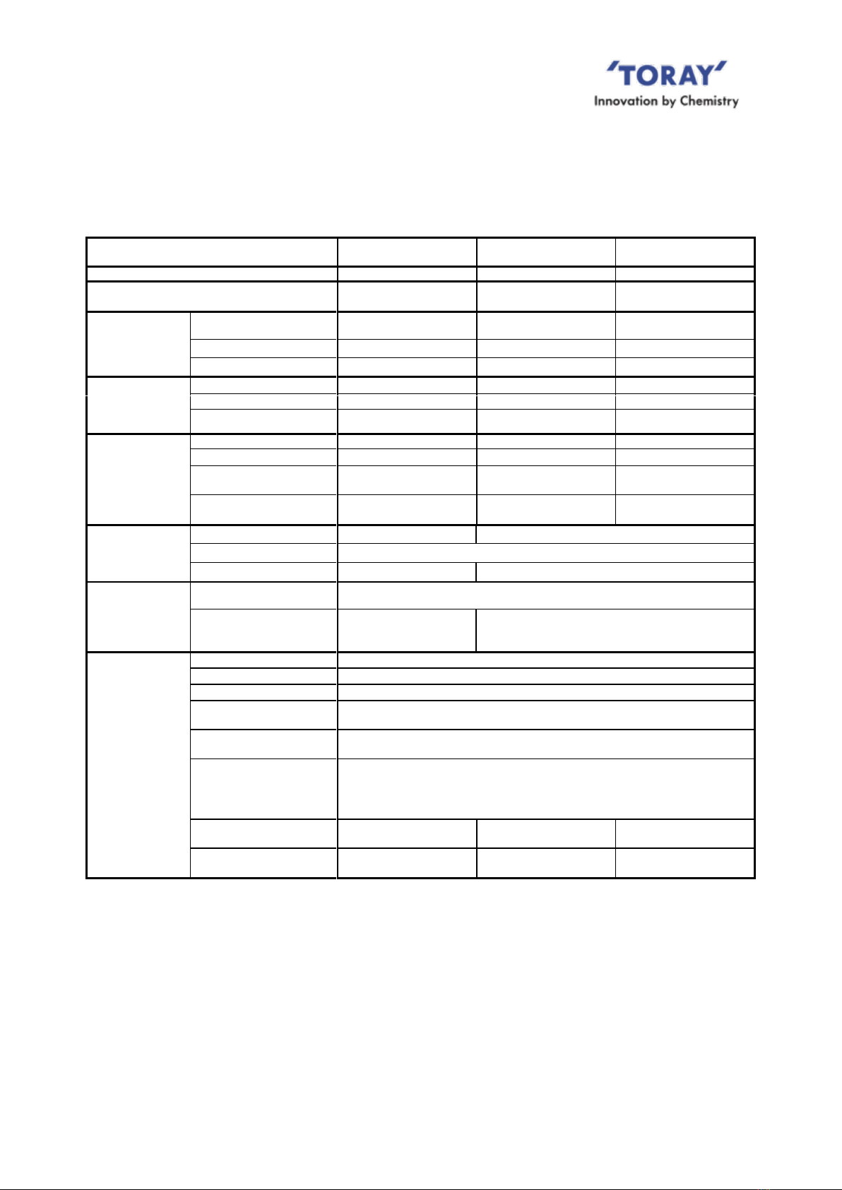
3. Specifications and Performance of “NHP210 Series”Module
Table III-3 shows the specifications of “NHP210 Series”cassette and module.
Table III-3 Specifications of Cassette and Module
Model name
ECS035
(Cassette)
NHP210-300S
(Standard module)
NHP210-600D
(Double-decker)
Number of membrane elements
50
300
600
Cassette structure
-
3 cassettes x 2 decks
3 cassettes x 4 decks
Overall
dimensions (mm)
Width
485
(excluding nozzle&hose)
770
770
Length
440
1,635
1,635
Height
820
2,175
3,845
Dimensions
excluding filtrate header
pipes and air diffuser
pipe
(mm)
Width
-
565
565
Length
-
1,460
1,460
Height
-
2,090
3,760
Weight
(kg)
Module (dry)
N/A
235
430
Aeration block (dry)
N/A
40
40
Cassette/Element block
(dry)
17
195
390
Cassette/Element block
(sludge clogging)*1
145
970
1,940
Material
Frame
-
304SS (316LSS is available as option)
Filtrate water manifold
Polypropylene
Air diffuser,
-
Polypropylene (SS is available as option)
Connection
Manifold
ANSI 1 1/2 inch flange using M12 bolts/nuts
One flange per each deck (300S: 2 pcs per module, 600D: 4 pcs per module)
Air diffuser
-
ANSI 1 1/2 inch flange
Using M12 bolts/nuts
Two flanges per Aeration block
Operating range*3
Temperature
5-40 degree C
pH*2 of liquid
5-10
MLSS
Not higher than 18,000 mg/L
Trans-membrane
pressure
Not higher than 20 kPa (200 mbar)
Cleaning chemicals feed
pressure
Not higher than 10 kPa (100 mbar)
Cleaning chemicals and
chemicals concentration
Sodium hypochlorite (effective chlorine concentration)
:2,000-6,000 mg/L(10<pH<12)
Oxalic acid :0.5-1.0wt%
Citric acid :1.0-3.0wt%
Scouring Air Flow rate
(NL/min/Module)*4
-*5
1,000 - 2,000
1,300 - 2,000
Scouring Air Flow rate
(Cubic feet/min/Module)*4
-*5
35 - 71
46 - 71
*1 The weight assumed in the case of sludge clogging between elements.
*2 Except when the chemical cleaning with the designated chemical agents.
*3 For the standard operating condition please refer Table VII-1.
*4 Air volume as being 0 degree C and 101.325 kPa (1 atm).
*5 MBR operation only by Cassette is not assumed.

NIRE-170-1-6
11
Table III-4 and III-5 shows the performance of ”NHP210 Series”modules.
Table III-4 Filtrate water quality
Model name
All models
Filtrate
water
quality*1
TSS (mg/L)*2
Not higher than 3.0
Turbidity (NTU)*3
Not higher than 1.0
*1 This value can be attained when operated under the standard operating conditions as specified in this
Instruction Manual and Operation and Maintenance guideline during a period specified separately by
Toray.
*2 Measuring method of TSS is complied with Standard Method of Examination of Water and Wastewater
20th Edition (1998), Section 2540D, Total Suspended Solids Dried at 103-105 degree C or ISO 11923.
*3 Measuring method of NTU is complied with Standard Method of Examination of Water and Wastewater
20th Edition (1998), Section 2130, Turbidity or ISO 7027.
Table III-5 Flow capacity (Reference value)
Model name
NHP210-300S
NHP210-600D
Filtration
Flow (m3/d)
*4
Sewage
20 - 150
40 - 300
Industrial wastewater
20 - 100
40 - 200
*4 This value is just a reference value and not a guarantee value of Toray. Sustainable operating filtration
flow capacity varies among the plant depending on the type of wastewater, total process design and
operating condition. In case of industrial wastewater application, it is strongly recommended to conduct
a pilot test before membrane tank designing.
NIRE-170-1-6
12
IV. MEMBRANE FILTRATION PROCESS DESIGN FOR “NHP210 SERIES”
This section will address the following for the Toray “NHP210 Series”: Standard sequence of
operation/time chart, illustrated piping and flow schematic, and module(s) layout in the
membrane tank.
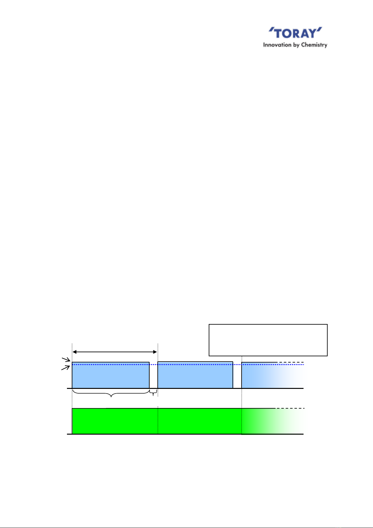
1. Standard Time Chart
Usually intermittent filtration (filtration with relaxation) is recommended. The most common
mode of filtration operation is nine (9) minutes of filtration followed by one (1) minute
of suspended membrane filtration (membrane relaxation) with continued air scour, as
shown in Fig.IV-1. This period of relaxation, with no filtration, allows the continued air scour
to be more effective at removing solids that may have accumulated on the surface of the
membrane. Intermittent filtration followed by a relaxation period is recommended for stable
and efficient membrane filtration.
The air scour should be suspended when the filtration process is stopped except for the
following conditions:
1) During normal membrane relaxation periods.
2) During suspended filtration operation unless aeration is required for mixing or biological
demand requirements. For the latter the air flow should be reduced to minimum flow
rates to prevent membrane damage.
* During low wastewater supply period, basically all modules should be in operation at lower
flux rate, considering maintaining viable activated sludge. In case operation of some or all
modules will be shut down, the air scour for those modules should be suspended or applied
intermittently following above description. For long-term shutdown please refer to the
following chapter 8 “Storage Products after Use”.
Fig.IV-1 Recommended Time Chart for Intermittent Filtration
Filtration
Air diffusion
Continuous
Filtration: 9 min.
Relaxation: 1 min.
Cycle of 10 minutes
F1: Average flow rate for treatment capacity
and membrane area calculation
F2: Filtration flow rate for suction pump
capacity calculation
F1
F2
NIRE-170-1-6
13
Membrane Module
FIC
FI
L
H
L:CLOSE
H:OPEN
L:OPEN
H:CLOSE
Filtrate water outlet
Manifold
Lower Limit alarm
Air Outlet
Feed
Chemical
Air Diffuser
Membrane
Tank
PIA
PIA
“U-shape”
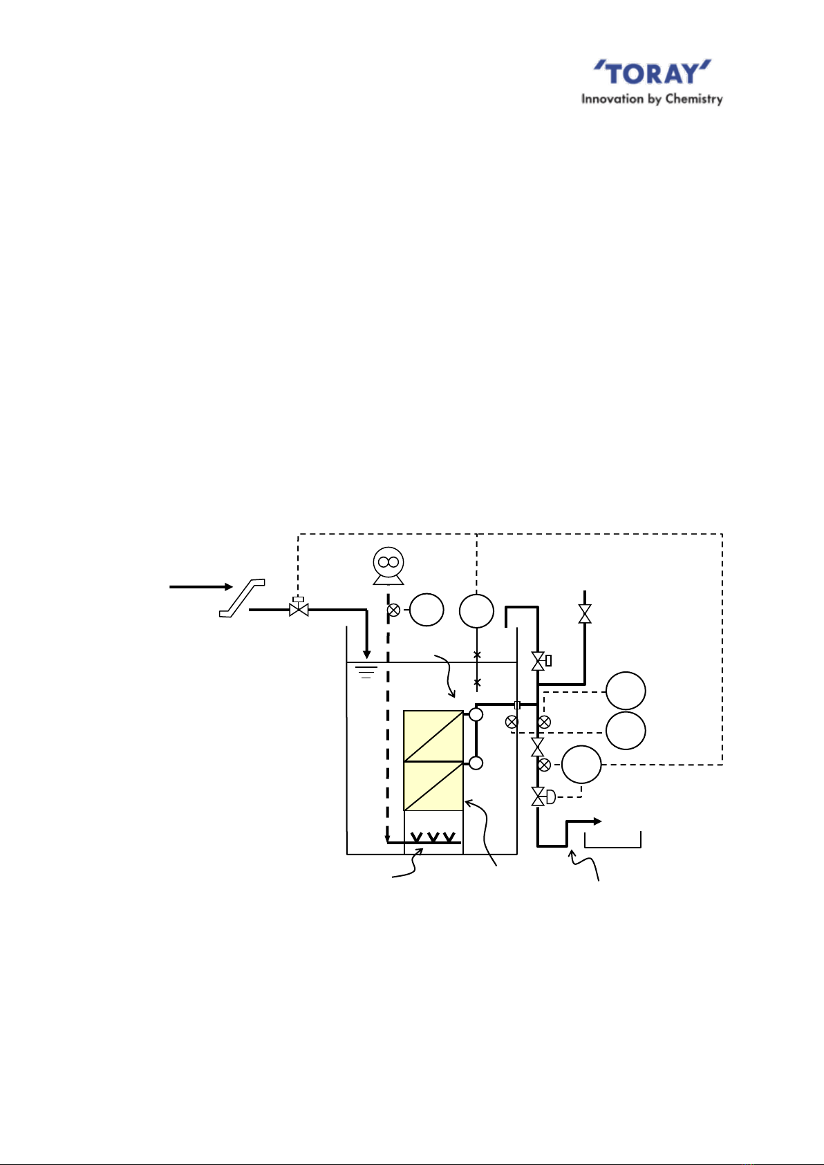
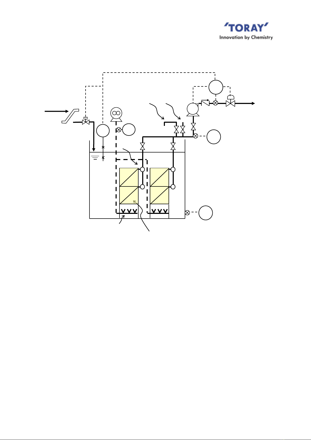
2. Flow Diagram of Membrane Filtration
Two (2) flow diagrams of the membrane filtration process are shown below. One is for gravity
filtration (when site conditions permit) and the other using a suction pump. Also depicted are
major ancillary devices required for the membrane filtration process.
To reduce the potential for membrane clogging, all activated sludge should pass
through a fine mesh screen having openings of 3 mm or less prior to being introduced
into the membrane tank. Failure to incorporate the screen device may result in large
solids clogging or causing physical damage to the membrane surfaces.
In order to equalize BOD load and filtration flow capacity it is recommended that a
buffer/equalization tank be installed to help stabilize operation of the biological treatment and
membrane filtration process.
(1) Gravity filtration configuration
The filtration process can be accomplished by using elevation differences between the liquid
level of the membrane tank and the level of the filtrate outlet (see Fig. IV-2).
Fig. IV-2 Schematic Flow Diagram for Gravity Filtration
In order to obtain enough suction pressure for the filtration process, consider friction loss of
all pipes and valves. In addition, the filtrate water outlet should be located at least 3 m below
the surface of membrane tank water level.
LS
Wastewater
Fine Screen
FIC: Flow Rate Indicator/Controller
LS : Level Switch
PIA: Pressure Indicator/Alarm
FI : Flow Meter

NIRE-170-1-6
14
It is recommended that the piping from the filtrate water manifold to the filtrate water
outlet should directly penetrate the tank wall, as shown in Fig.IV-2. In addition, if the
filtrate water outlet is an open air discharge, it is recommended that a U-shaped “trap” be
constructed to seal the filtrate piping with water.
The filtrate water flow rate is controlled with the automatic control valve (filtrate control valve).
When the liquid level of the membrane tank gets to the designed low level limit, the filtrate
control valve fully closes to effectively stop the filtration process. When the liquid level of the
membrane tank reaches the designed high level the automatic shut off valve on the raw
water influent line closes to stop raw water flow to the membrane tank.
In the gravity filtration mode air may accumulate in the filtrate water lines. To prevent
reduction or loss of suction the air in the filtrate line should be purged to atmosphere at least
once per day. The air purge nozzle should be installed at the highest position of the filtrate
water line. The line should also be fitted with an automatic shut off valve (the air purge valve)
just upstream of the air purge nozzle (As shown in Fig.IV-2). The filtration process should be
suspended for a few minutes while purging any entrained air from the filtrate line. Close the
filtrate control valve and open the air purge valve. After all air has been purged return the air
purge valve to the closed position and open the filtrate control valve.
NIRE-170-1-6
15
Membrane Module
Air diffuser
FIC
Filtrate water
Manifold
PIA
Lower limit alarm
Air outlet
Feed
chemical
FI
L
H
L:OPEN
H:CLOSE
L:CLOSE
H:OPEN
VFD or auto valve
PIA
(2) Pump suction configuration
Fig. IV-3 illustrates the general configuration for pump suction filtration.
Fig.IV-3 Schematic Flow Diagram for Pump Suction Operation
When incorporating a suction pump to facilitate water flow through the membrane, the filtrate
water flow rate should be controlled using a flow meter fitted with control output signals and a
suction pump fitted with a VFD device or an automatic control valve. In the event the
membrane tank water level reaches the lower level design set point the filtration mode
should be stopped. As with the gravity filtration mode previously discussed, should the
membrane tank water level reach the upper designed liquid level set point, the high level
controller will close the raw water inlet control valve.
Since the liquid in the tank contains a significant amount of dissolved air, some of that
dissolved air will accumulate in the filtrate pump suction line. It would be necessary to
periodically purge the filtrate line of any accumulated air and in this context it is quite
beneficial to locate the pump at the highest point of filtrate piping. A range of methods
can be used to remove air from the filtrate line: vacuum pump, ejector or manual water
injection. Contact Toray or refer to the engineering manual for the additional details.
Raw water
Fine screen
FIC : Flow rate indicator/Controller
LS : Level Switch
PIA : Pressure indicator/Alarm
FI : Flow indicator
LS

NIRE-170-1-6
16
PIA
a mm
P1
P2
PIA
b mm
(3) Required ancillary devices for membrane filtration process are listed below. In some
instances additional components may be required.
a. Fine screen
Incoming wastewater to the membrane tank should pass through a screen having
3.0 mm or less openings. Failure to incorporate a screening device will result in
clogging or permeant damage to the membrane. Mesh type screens are
recommended. Overflow or waste carryover into the submerge membrane tank must
be avoided at all times.
b. Flow control device
A flow rate controller, a flow meter combined with an automatic control valve, or a
flow meter combined with VFD controlled suction pump should be installed on the
filtrate water line to control the flow rate of filtrate water. When operating more than
one “NHP210 Series” module simultaneously it is recommended that each train be
fitted with its own discreet filtrate flow rate controller.
c. Trans-membrane pressure (TMP) measurement & calculation
For trans-membrane pressure (TMP) determination the differential pressure (in the
filtrate line and water level) needs to be measured and calculated. This can be
accomplished by either installing two pressure sensors and calculating the
difference in the readings in the PLC or using a differential pressure gauge.
When using two pressure gauges, one pressure gauge should be installed on the
filtrate water line and the other on the membrane tank, to monitor the
trans-membrane pressure. When operating a number of “NHP210 Series” modules
simultaneously in one train, it is advised to install one differential pressure
measuring instrument for each train.
[Example]
Fig.IV-4 Trans-Membrane Pressure Measurement & Calculation

NIRE-170-1-6
17
➢a = 1,000 mm (= 10 kPa, 100 mbar), b = 3,000 mm (= 30 kPa, 300 mbar)
➢PIA readings;
Filtration (pump ON)
Relaxation (pump OFF)
P1 (kPa)
29
30
P2 (kPa)
-15
-10
In this case, TMP is calculated as follows;
TMP= (P1Filtration - P1Relaxation) - (P2Filtration - P2Relaxation)= (29) - (30) - [(-15)-(-10)]= 4 kPa
* In case water level is stable, P1Filtration is equal to P1Relaxation. Then TMP is;
TMP = P2Relaxation - P2Filtration = -a - P2Filtration
d. Air supply unit (such as a blower)
This unit supplies air to the air diffusers of "NHP210 Series" module. The air flow
rate supplied to the module should be always within the range of "Scouring Air Flow
Rate" indicated in Table III-3.
e. Air flow meter.
An air flow meter is recommended to be installed to check the flow rate of the
scouring air supplied to the module. In case of operating a number of “NHP210
Series” modules simultaneously in a train, it is advised to install, at a minimum, one
air flow meter for each train.
f. Suction pump
A suction pump is required in the case of pump suction configuration. To achieve an
accurate designed filtrate flow rate the suction pump should be fitted with a VFD
controller. The use of a volute pump (centrifugal pump) or volumetric pump (screw
pump) with self-priming functions is recommended.
g. Level sensor
Level sensors are required to be installed in the membrane tank to monitor and
control the liquid level of the membrane tank and to facilitate calculating TMP via the
PLC.
h. Siphon breaking device on filtrate piping
When using a suction pump it may be necessary to have a means to break the
filtrate siphon if the filtrate discharge point is lower than water level of the membrane
tank. This siphon flow has to be avoided and filtrate flow has to be stopped
whenever pump stops.
It is required that a screen with openings of 3.0 mm or less be
installed prior to the membrane tank. A mesh type screen is
recommended. Avoid any overflow or waste carryover at all times.
CAUTION
!
Table of contents
Other Toray Industrial Equipment manuals


