Apex Digital XA3300 Parts list manual

XA Series OO1101
XA3300/XA4000/XA5000
Applicator
Operator Instructions and Parts Manual
Model _____________ Serial No. _____________
9281 LeSaint Drive • Fairfield, Ohio 45014
Phone (513) 874-2818 • Fax (513) 874-2914

FOR OFFICE USE ONLY
DATE UPDATE DESCRIPTION CODE
11/01/22 Initial release OO1101

What should you do if you need repairs or parts under Warranty?
How to get parts and or repairs done under warranty:
Notify YOUR DEALER immediately when you discover a faulty material, workmanship, or
faulty component. Do not wait weeks or months to get it reported. Be sure to tell the dealer
that this is a failure that occurred under warranty.
NOTE: Warranty work must be done by an Authorized Dealer in order to be covered by
the Warranty Program, unless otherwise approved by the Warranty Administrator.
Instructions to Dealer on processing warranty work:
Initiating a claim
1. Be sure to have the model, serial number and number of hours on unit.
2. A description of the problem as understood at the time.
3. Call the Warranty Administrator to secure warranty claim authorization number.
4. ConÞrm with Warranty Administrator that the unit is eligible for warranty coverage.
5. Any parts needed for the repair work should be placed with the Warranty Administrator
instead of the parts department. These will be shipped to you at no charge pending the
outcome of the investigation.
6. Labor hours must coincide with the published “Labor Schedule” or estimate approved
by the Finn Warranty Administrator.
7. Once work is done, a Warranty Claim Form must be Þlled out and emailed along with
any related receipts or invoices to the Warranty Administrator. We ask that this is done
ASAP after work is completed.
Faulty or failed parts:
IF the Warranty Administrator wants you to return failed parts, you will receive a return
shipping label in the package with new parts. On that Label will be marked a return
authorization number. (Which is the same number as you claim number.)
Please also mark the outside of the package that you are shipping back (using a marker)
with the claim/return number. THESE PARTS MUST BE RETURNED WITHIN 10 DAYS!
Failure to do so can void warranty coverage.
NOTE: Further information and related forms can be found on the web site in the Dealer
Portal warranty section.
ACTIVATE YOUR EQUIPMENT WARRANTY
It is the responsibility of the Dealer to register your Equipment shortly after the equipment
start-up and operation overview. You must register your machine at time of purchase at
www.apexseeder.com/warranty/ for warranty coverage.
Be sure to conÞrm with your sales representative that this has been done completely.
This registration process activates the Limited Warranty.


Continued...
INDEX
Safety Information . . . . . . . . . . . . . . . . . . . . . . . . . . . . . . . . . . . . . . . . . . . . . . . . . . . . . . . . . . . . . 1 - 4
Safety Summary . . . . . . . . . . . . . . . . . . . . . . . . . . . . . . . . . . . . . . . . . . . . . . . . . . . . . . . . . . . 2 - 4
Training . . . . . . . . . . . . . . . . . . . . . . . . . . . . . . . . . . . . . . . . . . . . . . . . . . . . . . . . . . . . . . . . . . . . . . . 5
Hauling and Towing . . . . . . . . . . . . . . . . . . . . . . . . . . . . . . . . . . . . . . . . . . . . . . . . . . . . . . . . . . . . . . 5
Safety While Refueling . . . . . . . . . . . . . . . . . . . . . . . . . . . . . . . . . . . . . . . . . . . . . . . . . . . . . . . . . . . 5
Pre-Operation Inspections . . . . . . . . . . . . . . . . . . . . . . . . . . . . . . . . . . . . . . . . . . . . . . . . . . . 6 - 10
Pre-Operation Checklist . . . . . . . . . . . . . . . . . . . . . . . . . . . . . . . . . . . . . . . . . . . . . . . . . . . . . . . 6
Re-Filling Fuel . . . . . . . . . . . . . . . . . . . . . . . . . . . . . . . . . . . . . . . . . . . . . . . . . . . . . . . . . . . . . . . 7
DEF Location. . . . . . . . . . . . . . . . . . . . . . . . . . . . . . . . . . . . . . . . . . . . . . . . . . . . . . . . . . . . . . . . 7
Check Engine Oil Level. . . . . . . . . . . . . . . . . . . . . . . . . . . . . . . . . . . . . . . . . . . . . . . . . . . . . . . . 7
Check Engine Coolant Level. . . . . . . . . . . . . . . . . . . . . . . . . . . . . . . . . . . . . . . . . . . . . . . . . . . . 8
Re-Filling DEF . . . . . . . . . . . . . . . . . . . . . . . . . . . . . . . . . . . . . . . . . . . . . . . . . . . . . . . . . . . . . . . 8
Fuel/ Water Separator . . . . . . . . . . . . . . . . . . . . . . . . . . . . . . . . . . . . . . . . . . . . . . . . . . . . . . . . . 8
Check Hydraulic Filter Restriction Indicators . . . . . . . . . . . . . . . . . . . . . . . . . . . . . . . . . . . . . . . 9
Verify Lighting . . . . . . . . . . . . . . . . . . . . . . . . . . . . . . . . . . . . . . . . . . . . . . . . . . . . . . . . . . . . . . . 9
General Operator Safety Guidelines . . . . . . . . . . . . . . . . . . . . . . . . . . . . . . . . . . . . . . . . . . . . . . 9
Applicator Preparation and Maintenance . . . . . . . . . . . . . . . . . . . . . . . . . . . . . . . . . . . . . . . 9 - 10
Preventative Maintenance. . . . . . . . . . . . . . . . . . . . . . . . . . . . . . . . . . . . . . . . . . . . . . . . . . . . . 10
Safety While Maintaining. . . . . . . . . . . . . . . . . . . . . . . . . . . . . . . . . . . . . . . . . . . . . . . . . . . . . . 10
Entering and Exiting the Operator Station. . . . . . . . . . . . . . . . . . . . . . . . . . . . . . . . . . . . . . . . . 10
Operation And Maintenance Manual . . . . . . . . . . . . . . . . . . . . . . . . . . . . . . . . . . . . . . . . . . . . . . . . . . .11 - 31
Equipment Description . . . . . . . . . . . . . . . . . . . . . . . . . . . . . . . . . . . . . . . . . . . . . . . . . . . . . . 11
Reference Information . . . . . . . . . . . . . . . . . . . . . . . . . . . . . . . . . . . . . . . . . . . . . . . . . . . . . . 11
Orientation . . . . . . . . . . . . . . . . . . . . . . . . . . . . . . . . . . . . . . . . . . . . . . . . . . . . . . . . . . . . . . . 11
Operator Platform. . . . . . . . . . . . . . . . . . . . . . . . . . . . . . . . . . . . . . . . . . . . . . . . . . . . . . . . . . 12
Operator Control Panel . . . . . . . . . . . . . . . . . . . . . . . . . . . . . . . . . . . . . . . . . . . . . . . . . 12 - 13
Controller Master Display . . . . . . . . . . . . . . . . . . . . . . . . . . . . . . . . . . . . . . . . . . . . . . . . . . 12
Home Screen. . . . . . . . . . . . . . . . . . . . . . . . . . . . . . . . . . . . . . . . . . . . . . . . . . . . . . . . . . . . 13
Slurry Pump Control . . . . . . . . . . . . . . . . . . . . . . . . . . . . . . . . . . . . . . . . . . . . . . . . . . . . . . 13
Engine Screen . . . . . . . . . . . . . . . . . . . . . . . . . . . . . . . . . . . . . . . . . . . . . . . . . . . . . . . . . . . 14
Engine Lamps . . . . . . . . . . . . . . . . . . . . . . . . . . . . . . . . . . . . . . . . . . . . . . . . . . . . . . . .14 - 15
Regeneration Cycle . . . . . . . . . . . . . . . . . . . . . . . . . . . . . . . . . . . . . . . . . . . . . . . . . . . . . . . 15
Regeneration Inhibit . . . . . . . . . . . . . . . . . . . . . . . . . . . . . . . . . . . . . . . . . . . . . . . . . . . . . . 15
Agitator Control . . . . . . . . . . . . . . . . . . . . . . . . . . . . . . . . . . . . . . . . . . . . . . . . . . . . . . . . . . 16
Slurry Control. . . . . . . . . . . . . . . . . . . . . . . . . . . . . . . . . . . . . . . . . . . . . . . . . . . . . . . . . . . . 16
Ground Level Controls. . . . . . . . . . . . . . . . . . . . . . . . . . . . . . . . . . . . . . . . . . . . . . . . . . . . . 16
Loading Platform . . . . . . . . . . . . . . . . . . . . . . . . . . . . . . . . . . . . . . . . . . . . . . . . . . . . . . . . . . 17
Emergency Stop (E-Stop) Button . . . . . . . . . . . . . . . . . . . . . . . . . . . . . . . . . . . . . . . . . . . . 17
Loading Hatch . . . . . . . . . . . . . . . . . . . . . . . . . . . . . . . . . . . . . . . . . . . . . . . . . . . . . . . . . . . 17
Storage Platform . . . . . . . . . . . . . . . . . . . . . . . . . . . . . . . . . . . . . . . . . . . . . . . . . . . . . . . . . . 17
Starting Procedure . . . . . . . . . . . . . . . . . . . . . . . . . . . . . . . . . . . . . . . . . . . . . . . . . . . . . 18 - 19
Pre-Operation Warm-Up . . . . . . . . . . . . . . . . . . . . . . . . . . . . . . . . . . . . . . . . . . . . . . . . . . . 18
Starting with Jumper Cables . . . . . . . . . . . . . . . . . . . . . . . . . . . . . . . . . . . . . . . . . . . . . . . . 19
Stopping the Engine . . . . . . . . . . . . . . . . . . . . . . . . . . . . . . . . . . . . . . . . . . . . . . . . . . . . . . 19
Operating Instructions . . . . . . . . . . . . . . . . . . . . . . . . . . . . . . . . . . . . . . . . . . . . . . . . . . 20 - 25
Filling The Tank . . . . . . . . . . . . . . . . . . . . . . . . . . . . . . . . . . . . . . . . . . . . . . . . . . . . . . . . . . 20
Mixing Materials. . . . . . . . . . . . . . . . . . . . . . . . . . . . . . . . . . . . . . . . . . . . . . . . . . . . . . . 20 - 21
Application of Product . . . . . . . . . . . . . . . . . . . . . . . . . . . . . . . . . . . . . . . . . . . . . . . . . . 21 - 24
Reloading Procedure. . . . . . . . . . . . . . . . . . . . . . . . . . . . . . . . . . . . . . . . . . . . . . . . . . . . . . 25

INDEX (Continued)
Operation And Maintenance Manual (Continued)
Cleaning and Maintenance. . . . . . . . . . . . . . . . . . . . . . . . . . . . . . . . . . . . . . . . . . . . . . . 26 - 30
Daily . . . . . . . . . . . . . . . . . . . . . . . . . . . . . . . . . . . . . . . . . . . . . . . . . . . . . . . . . . . . . . . . . 26
Weekly . . . . . . . . . . . . . . . . . . . . . . . . . . . . . . . . . . . . . . . . . . . . . . . . . . . . . . . . . . . . . . . 26
Monthly . . . . . . . . . . . . . . . . . . . . . . . . . . . . . . . . . . . . . . . . . . . . . . . . . . . . . . . . . . . . . . . 26
Fluids And Components . . . . . . . . . . . . . . . . . . . . . . . . . . . . . . . . . . . . . . . . . . . . . . 27 - 28
Lubricating Grease . . . . . . . . . . . . . . . . . . . . . . . . . . . . . . . . . . . . . . . . . . . . . . . . . . 28 - 29
Fuse Panel . . . . . . . . . . . . . . . . . . . . . . . . . . . . . . . . . . . . . . . . . . . . . . . . . . . . . . . . . . . . 29
Hydraulic Filter Restriction Indicator . . . . . . . . . . . . . . . . . . . . . . . . . . . . . . . . . . . . . . . . . 29
Short Term Storage . . . . . . . . . . . . . . . . . . . . . . . . . . . . . . . . . . . . . . . . . . . . . . . . . . . . . 30
Long Term Storage . . . . . . . . . . . . . . . . . . . . . . . . . . . . . . . . . . . . . . . . . . . . . . . . . . . . . . 30
Engine Storage. . . . . . . . . . . . . . . . . . . . . . . . . . . . . . . . . . . . . . . . . . . . . . . . . . . . . . . . . 30
Disposal Procedure . . . . . . . . . . . . . . . . . . . . . . . . . . . . . . . . . . . . . . . . . . . . . . . . . . . . . 30
Maintenance Chart . . . . . . . . . . . . . . . . . . . . . . . . . . . . . . . . . . . . . . . . . . . . . . . . . . . . . . . . . 31
Applicator Dimensions . . . . . . . . . . . . . . . . . . . . . . . . . . . . . . . . . . . . . . . . . . . . . . . . . . . . . . 32
Parts Section . . . . . . . . . . . . . . . . . . . . . . . . . . . . . . . . . . . . . . . . . . . . . . . . . . . . . . . . . . . . 33 - 77
Railings . . . . . . . . . . . . . . . . . . . . . . . . . . . . . . . . . . . . . . . . . . . . . . . . . . . . . . . . . . . . . . . . . . . 35
Agitators . . . . . . . . . . . . . . . . . . . . . . . . . . . . . . . . . . . . . . . . . . . . . . . . . . . . . . . . . . . . . . . 36 - 37
Engine Mount . . . . . . . . . . . . . . . . . . . . . . . . . . . . . . . . . . . . . . . . . . . . . . . . . . . . . . . . . . . 38 - 39
Radiator Hoses . . . . . . . . . . . . . . . . . . . . . . . . . . . . . . . . . . . . . . . . . . . . . . . . . . . . . . . . . . . . . 40
Hydraulic Pump - Slurry Pump . . . . . . . . . . . . . . . . . . . . . . . . . . . . . . . . . . . . . . . . . . . . . . . . . 41
Hydraulic Pump - Left Agitator . . . . . . . . . . . . . . . . . . . . . . . . . . . . . . . . . . . . . . . . . . . . . . 42 - 43
Hydraulic Pump - Right Agitator . . . . . . . . . . . . . . . . . . . . . . . . . . . . . . . . . . . . . . . . . . . . . 44 - 45
Primary Discharge Boom . . . . . . . . . . . . . . . . . . . . . . . . . . . . . . . . . . . . . . . . . . . . . . . . . . . . . 46
Slurry Pump Assembly . . . . . . . . . . . . . . . . . . . . . . . . . . . . . . . . . . . . . . . . . . . . . . . . . . . . . . . 47
Slurry Pump. . . . . . . . . . . . . . . . . . . . . . . . . . . . . . . . . . . . . . . . . . . . . . . . . . . . . . . . . . . . . 48 - 49
Air Cleaner. . . . . . . . . . . . . . . . . . . . . . . . . . . . . . . . . . . . . . . . . . . . . . . . . . . . . . . . . . . . . . . . . 50
Fuel Tank . . . . . . . . . . . . . . . . . . . . . . . . . . . . . . . . . . . . . . . . . . . . . . . . . . . . . . . . . . . . . . . . . . 51
Aftertreatment . . . . . . . . . . . . . . . . . . . . . . . . . . . . . . . . . . . . . . . . . . . . . . . . . . . . . . . . . . . 52 - 53
Hydraulic Schematic . . . . . . . . . . . . . . . . . . . . . . . . . . . . . . . . . . . . . . . . . . . . . . . . . . . . . . 54 - 55
Hydraulic Tank . . . . . . . . . . . . . . . . . . . . . . . . . . . . . . . . . . . . . . . . . . . . . . . . . . . . . . . . . . . 56 - 57
Hydraulic Oil Cooler . . . . . . . . . . . . . . . . . . . . . . . . . . . . . . . . . . . . . . . . . . . . . . . . . . . . . . . . . 58
Agitator Motor 1 Hydraulic System Connectors . . . . . . . . . . . . . . . . . . . . . . . . . . . . . . . . . . . . 59
Agitator Motor 2 Hydraulic System Connectors . . . . . . . . . . . . . . . . . . . . . . . . . . . . . . . . . . . . 60
Hydraulic Return Manifold . . . . . . . . . . . . . . . . . . . . . . . . . . . . . . . . . . . . . . . . . . . . . . . . . . . . . 61
Engine Oil Filter. . . . . . . . . . . . . . . . . . . . . . . . . . . . . . . . . . . . . . . . . . . . . . . . . . . . . . . . . . . . . 62
Hydraulic Filter 2 . . . . . . . . . . . . . . . . . . . . . . . . . . . . . . . . . . . . . . . . . . . . . . . . . . . . . . . . . . . . 63
Hydraulic Filter 3 . . . . . . . . . . . . . . . . . . . . . . . . . . . . . . . . . . . . . . . . . . . . . . . . . . . . . . . . . . . . 64
Hydraulic Filter 4 . . . . . . . . . . . . . . . . . . . . . . . . . . . . . . . . . . . . . . . . . . . . . . . . . . . . . . . . . . . . 65
Primary Fuel Filter . . . . . . . . . . . . . . . . . . . . . . . . . . . . . . . . . . . . . . . . . . . . . . . . . . . . . . . . . . . 66
Secondary Fuel Filter . . . . . . . . . . . . . . . . . . . . . . . . . . . . . . . . . . . . . . . . . . . . . . . . . . . . . . . . 67
Nozzles . . . . . . . . . . . . . . . . . . . . . . . . . . . . . . . . . . . . . . . . . . . . . . . . . . . . . . . . . . . . . . . . . . . 68
Drain Pipes . . . . . . . . . . . . . . . . . . . . . . . . . . . . . . . . . . . . . . . . . . . . . . . . . . . . . . . . . . . . . . . . 69
Undercarriage Mounts. . . . . . . . . . . . . . . . . . . . . . . . . . . . . . . . . . . . . . . . . . . . . . . . . . . . . . . . 70
Mount Placement. . . . . . . . . . . . . . . . . . . . . . . . . . . . . . . . . . . . . . . . . . . . . . . . . . . . . . . . . 72 - 73
Control Tower . . . . . . . . . . . . . . . . . . . . . . . . . . . . . . . . . . . . . . . . . . . . . . . . . . . . . . . . . . . 74 - 75
Second Boom Option (91-90-0029) . . . . . . . . . . . . . . . . . . . . . . . . . . . . . . . . . . . . . . . . . . 76 - 77
1- 1/4 in. Hose Reel Option (91-90-0030) . . . . . . . . . . . . . . . . . . . . . . . . . . . . . . . . . . . . . . 78 - 79
1- 1/2 in. Hose Reel Option (91-90-0036) . . . . . . . . . . . . . . . . . . . . . . . . . . . . . . . . . . . . . . 80 - 81
Wiring Diagrams . . . . . . . . . . . . . . . . . . . . . . . . . . . . . . . . . . . . . . . . . . . . . . . . . . . . . . . . . . . 82 - 113

1
SAFETY FIRST
With any piece of equipment, new or used, the most important part of its operation is SAFETY!
Apex encourages you and your employees to familiarize yourselves with your new equipment and
stresses safe operation.
The first pages of this manual are a summary of the main safety aspects associated with this unit.
Be sure to read and understand completely before operating the machine.
The symbols below are used throughout the operation and maintenance sections of
this manual to call attention to safety procedures.
Danger indicates an imminently hazardous situation which,
if not avoided, WILL result in death or serious injury.
Warning indicates a potentially hazardous situation which,
if not avoided, COULD result in death or serious injury.
Caution indicates a potentially hazardous situation which,
if not avoided, MAY result in minor or moderate injury.
Notice indicates important information, that if not followed,
MAY cause damage to equipment.
NOTE: This is helpful information.
CALIFORNIA PROPOSITION 65
The engine exhaust and some of its constituents are known
to the State of California to cause cancer, birth defects, and
other reproductive harm. Wear protective equipment. To minimize exposure, avoid
breathing exhaust, do not idle the engine except as necessary, service your vehicle
in a well-ventilated area and wear gloves or wash your hands frequently when
servicing your vehicle.
Breathing diesel engine exhaust exposes you to chemicals
known to the State of California to cause cancer and birth
defects or other reproductive harm.
Always start and operate the engine in a well-ventilated area.
If in an enclosed area, vent the exhaust to the outside.
Do not modify or tamper with the exhaust system.
Do not idle the engine except as necessary.
Battery posts, terminals, and related accessories contain lead and
lead compounds, chemicals known to the State of California to cause
cancer and reproductive harm. Wash hands after handling.
This product can expose you to chemicals, including lead, which are
known to the State of California to cause cancer and birth defects or
other reproductive harm. Go to www.P65Warnings.ca.gov for more information.
The DANGER, WARNING, CAUTION and NOTICE notifications and instructions in this manual
cannot cover all possible conditions and situations that may occur.
It must be understood by the operator that caution is a factor which cannot be built into this
product; caution must be supplied by the operator.

2
SAFETY SUMMARY SECTION
It is important that all operators of this machine are familiar with all safety aspects
covered in this section and have read the entire Operator’s Manual before operating
the machine. Always keep a copy of this manual with the machine. It is the
responsibility of the operator of the machine to fully understand this safety summary
section. Remember that YOU are the key to safety. Good safety practices protect
not only you but also the people working with and around you. Keep in mind that this safety
section is written for this type of machine only. Practice all other usual and customary safe working
precautions. Above all, remember that safety is up to you.
The Apex XA Series Applicator is designed to mix and apply water, seed, fertilizer, agricultural lime,
and hydraulic mulch to the prepared seedbed. The resultant slurry from mixing one or more of the
above materials may react, causing harmful or deadly gasses within the tank. Heat, evaporation, or
extended emptying period can/will accelerate the formation of these gasses. Please contact your
supplier(s) of these slurry components regarding their potential reactivity.
I. PRIOR TO OPERATION
1. Read this manual in its
entirety and follow ALL safety
procedures
2. Check all lubrication points and fluid
levels. See lubrication section for specific
lubrication points and fluid specifications.
3.Inspect all fasteners for tightness with the
power turned off.
Obey all of the safety labels on the applicator.
They are provided for your protection. If
any labels are removed, damaged or made
unreadable in any way, contact Apex for a
replacement.
If the applicator is equipped with any options,
read and understand ALL of the safety
precautions and warnings for that particular
option BEFORE performing maintenance or
operating.
II. GENERAL PRECAUTIONS
1. Empty the tank daily to prevent stored
material from producing hazardous gases.
Some gases produced by stored material
can be harmful or deadly.
2. Never enter the tank of the
applicator before performing
the proper lockout/tagout
procedure. Use lockout/tagout
procedure 29 CFR 1910.147
during inspection or maintenance.
3. Tag the engine operating area to show
that the applicator is being serviced. Use
lockout / tagout procedure 29 CFR 1910.147
during inspection or maintenance.
4. Stop all action, read and
observe the operation and
safety manual in its entirety,
following all safety precautions
before operating or performing
maintenance.
5. Do not operate the applicator
without all guards in place.
Always use safe operating
practices.
6. Hydraulic fluid is under high
pressure. Always use safe
operating procedure.
7. Keep a sufficient distance away
from all electrical power lines.
8. Operators of the applicator
should never ride on the
machine at speeds greater
than 5 mph (8 kmh).
9. Use proper means (steps,
ladder) for mounting and
dismounting of the applicator.
Never mount or dismount a
moving machine.

3
III. WELDING PRECAUTIONS
Never perform welding on the XA Series
Applicator without disconnecting the following:
1. Move the
Master
Power
Switch to
the OFF
position.
2. Disconnect the Apex display by disconnecting
the connector inside the Operator Control
Box.
Remove the 4 bolts
on the back of the
Operator Control
Panel to access the
connector on the
display.
3. Disconnect the batteries, located on the right
side of the unit, behind the engine door.
Remove the positive
battery cable from
both batteries.
4. Disconnect the MC2
Apex microcontroller.
Locate the
microcontroller on
the engine frame on
the right side of the
engine, accessible
through the engine
access door.
5. Disconnect both connectors on the engine
ECU.
1. Depress the
button (1) to
allow the clasp
to raise.
2. Raise the clasp
to remove
the controller
connector (2).
II. GENERAL PRECAUTIONS (Continued)
10. Always wear safety
goggles when
operating the
applicator. Other
safety attire such
as safety shoes,
ear protection,
gloves, hard hats,
dust masks, etc,
should be worn
as required by
warning decals on
the machine, in the
operator’s manual
or specific job site
requirements. Avoid loose fitting clothing
that may get caught in rotating machinery.
Remove watches, rings, etc.
11. Do not load the applicator while in transit.
Load only when parked and unit is as level
as possible. Take care not to drop foreign
objects into the tank, such as pens, lighters,
etc, as the objects could plug the slurry
system. Should any object be dropped into
the tank, DO NOT reach into the tank to
retrieve the object. See the Maintenance
section before allowing any personnel to
enter the tank.
12. The driver of the carrying or towing
vehicle is responsible for the safety of the
operator(s) of the applicator. Make sure
the driver is aware and avoids all possible
hazards to the operator(s), such as low
tree limbs, low power lines, etc. Vehicles
on which the applicator is mounted must be
stopped and started gradually. Avoid abrupt
starts and stops. Never operate on a slope
or a hill that may endanger the driver and/or
the operator(s). All personnel should review
and be familiar with stop and start signals
between the driver and the operator(s)
before going into operation. Only the
operator should be located on the platform
during operation.
13. Never operate this or any other machine
when fatigued, tired, under the influence
of alcohol, illegal drugs or medication. All
personnel must be in good physical and
mental condition to operate this applicator.
14. Make sure the area to be sprayed is clear of
all persons and animals.
M
S
D
S

4
IV. OPERATION SAFETY
1. The noise level of the applicator at the
operator station, unshielded, is above
80dBA. Take the following precautions:
Always keep doors and windows of the tow
vehicle closed
Use ANSI S3 19-1975 approved hearing
protectors with a noise reduction rating
(NRR) of 25 dB (A)
Ear plugs (disposable or re-useable)
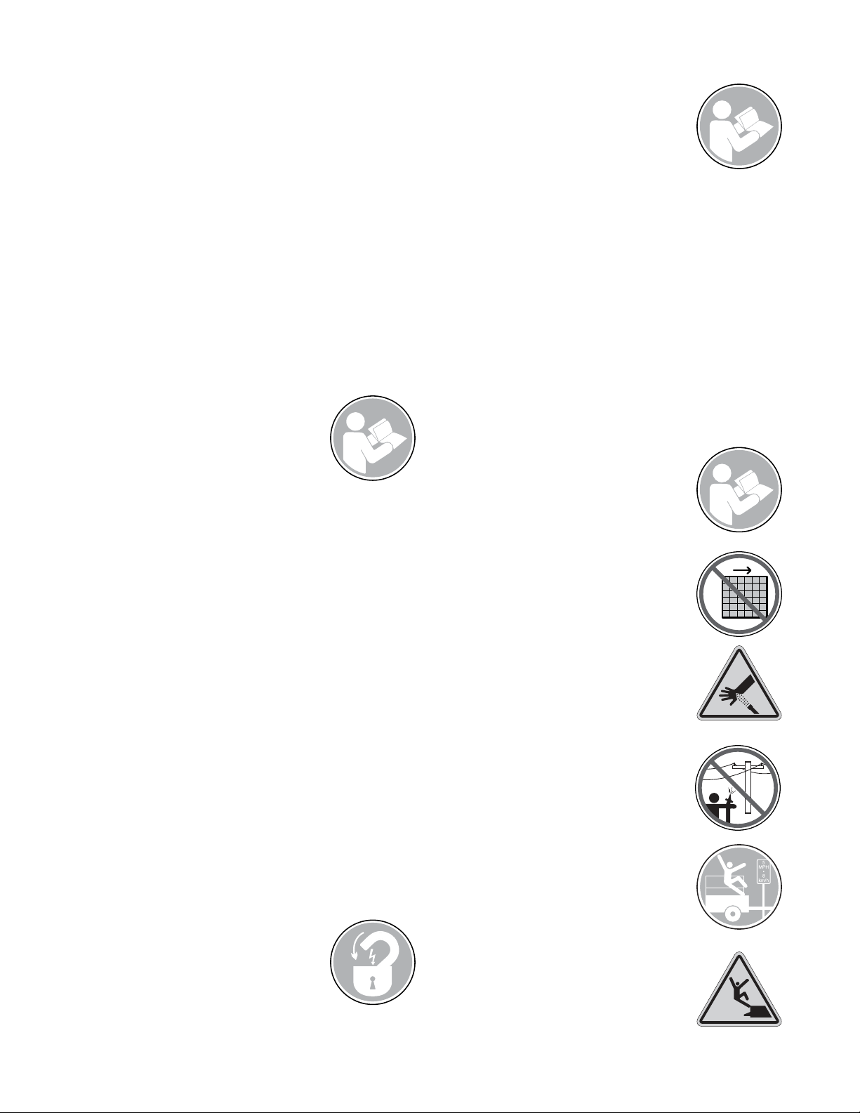
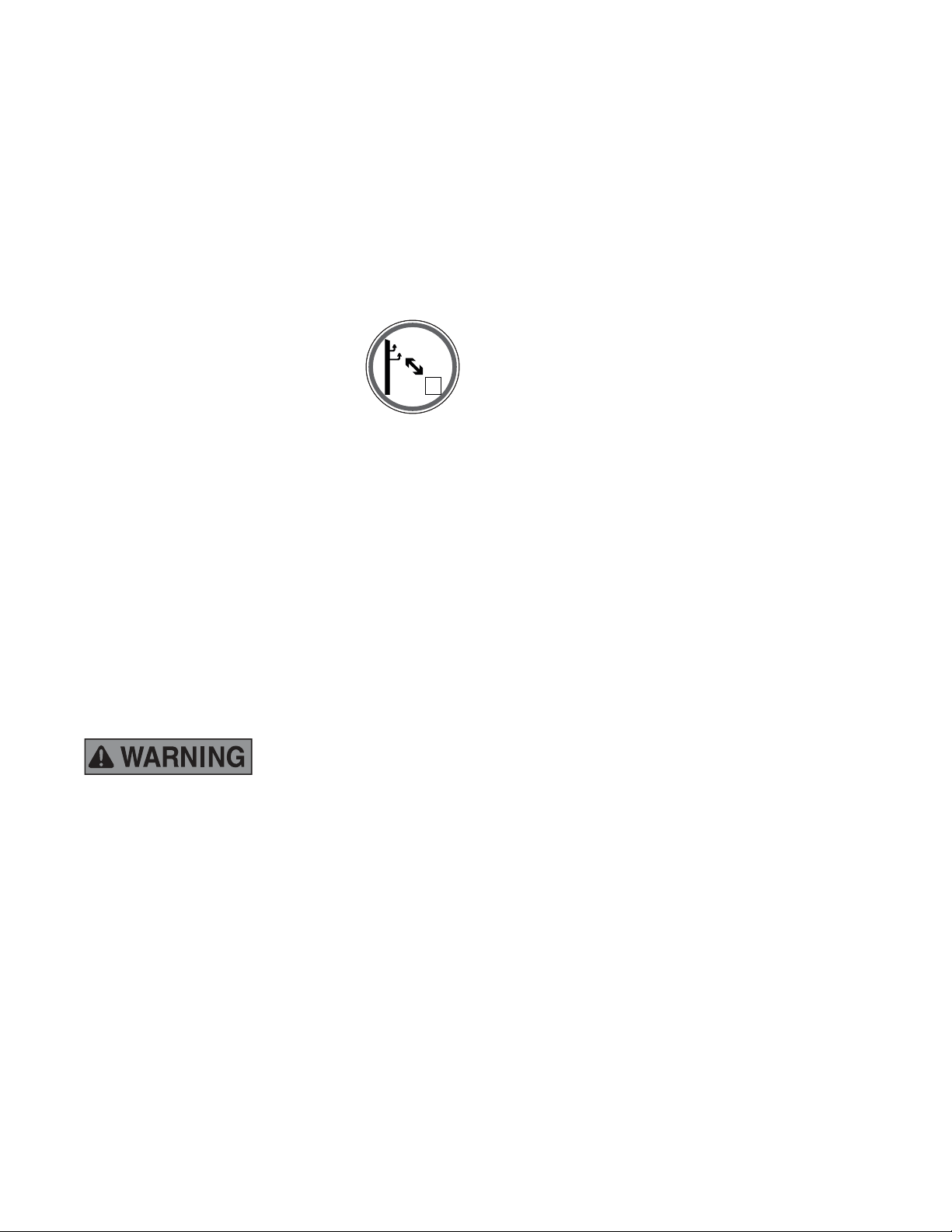
2. Avoid Power Lines. Serious
injury or death can result from
contact with electric lines.
Never move any part of the
equipment closer than 10 ft.
(3 m) plus twice the line insulator length to
an electric line. Use a signal person to guide
the operator. Use shrouds or insulators as
necessary.
3. It is the operator’s responsibility to ensure the
tow vehicle is properly maintained, including
safety lighting and notifications. Do not use
a tow vehicle before properly testing the
road-worthiness.
Tire Pressure
Functioning traffic lights
Properly attached
Break-Away Switch
Tongue weight
Ensure that the tow
vehicle has the capacity
to control the fully-loaded XA unit. Applicator
weights are listed in this manual.
4. Handle the battery with care. When removing
or installing the battery, check which is the
negative and positive terminal.
Removing Batteries:
1. Disconnect the (-) terminal connected to
the ground wire
2. Disconnect the (+) terminal connected to
the starter
When installing the batteries, follow this
procedure in reverse order.
Tighten the battery terminals securely; check
that the terminals are not lose by trying
to move the cables by hand. Loosened
cables can generate sparks and lead to an
explosion.
5. Never enter the tank through the loading
hatch or riser atop the tank. Remove
the fasteners securing the access panel
adjacent to the loading hatch and utilize a
ladder or steps to enter here.
Your slurry tank may be considered a
confined space by OSHA under 29 CFR
1910.146. Before entering any confined
space, your company must develop a
procedure for safe entry. Make sure your
company’s plan meets all the requirements
of 29 CFR 1910.146, and/or all applicable
laws and regulations.
6. Before loosening any clamps or opening any
valves, determine if material in the line is hot
by feeling the pipe. Do NOT allow material
to come in contact with personnel. Severe
bodily injury could result.
7. Radiator maintenance: Liquid cooling systems
build up pressure as the engine gets hot.
Before removing radiator cap, stop the
engine and let the system cool. Remove
radiator cap only after the coolant is cool.
8. Filling of fuel: Never fill the tank with the
engine running, while smoking, or when
near an open flame. Never smoke while
handling fuel or working on the fuel system.
The fumes in an empty fuel container are
explosive. Never cut or weld on fuel lines,
tanks, or containers. Move at least 10 ft.
(3 m) away from fueling point before starting
engine. Wipe off any spilled fuel and let dry
before starting engine.
IMPORTANT: Be careful not to allow fuel,
lubricant, hydraulic fluid, or cooling fluids to
penetrate into the ground or be discharged
into the water system. Collect all fluids
and dispose of them in accordance with all
applicable laws and regulations.
9. To prevent fires, remove all fiber mulch,
leaves, paper and other flammable material
accumulated in the engine compartment or
other places on the applicator. This could
cause a fire.
Marshland, when dry, is highly flammable.
Marshland can self-ignite even in low
temperatures. Always keep the engine
compartment and engine clean.
SAFETY SUMMARY SECTION (CONTINUED)

5
TRAINING
BEFORE operating this equipment read the following guidelines. This will help to you to minimize
the hazards associated with the use of the XA Series Applicator. Not all situations will apply to your
unit since the applicator configuration and specific job requirements will vary considerably.
The XA Series Applicator must only be operated by a trained and qualified operator who is
familiar with the controls and their use.
Read the Operation Section PRIOR to operating the machine in order to learn how to use the
control devices properly.
Be sure you understand the meaning of the WARNING signs and other CAUTION messages
throughout this manual.
Remember the check points and the method for checking fluid levels.
Visually inspect the machine and check the function of all lighting and instruments before use.
Frequently check the instrument panel. Do not operate the XA Series Applicator when the
display indicates a malfunction or error.
HAULING AND TOWING
The following items should be checked before transporting the applicator. These safety items are in
place to protect personnel during operation as well as during transportation between jobsites.
Check that all turn signals and brake lights are functioning properly. Correct any
nonfunctioning lights immediately.
Check tires for proper inflation (110 psi).
Operating or transporting with faulty safety devices is extremely
dangerous. Failure to correct any of these components could result in
severe personal injury or death.
SAFETY WHILE REFUELING
Diesel fuel is flammable and explosive under certain circumstances. Observe these safety practices:
Always handle fuel in a well-ventilated area.
Do not smoke or allow open flames or sparks in the vicinity.
Do not refuel with the engine hot or running.
Avoid physical contact with diesel fuel.
Regularly inspect fuel system components.
If fuel or fumes are noted while operating the XA4000, the cause should be determined
immediately.
Never open the fuel lines or loosen the injectors if the applicator runs out of fuel.
Avoid inhalation of exhaust particulate dust. Wear a dust mask. If respiratory irritation or
discomfort occurs, leave the dusty area. Utilize breathing assistance or oxygen if necessary.
Elevated concentrations of metals in the form of dust, soot, and contaminates are contained in
these filters. Health regulations may exist for the materials found in these filters such as Zinc,
Molybenum, polynuclear aromatic sulfur, and iron.
Proper disposal of the exhaust dust and filter are required. Dispose of in accordance with local
and environmental regulations.
Diesel particulate filter maintenance MUST be completed by appropriately trained personnel.

6
PRE-OPERATION INSPECTIONS
The Pre-Operation Inspection that an operator does before starting a piece of equipment is the
single most important responsibility of the day. The operator is the key component in the walk-around
and it is their responsibility to solicit help as required if areas of distress or concern are noted.
Cell phones and digital pictures are extremely helpful when communicating potential problems or
concerns.
Many operators overlook vital aspects of the walk-around such as fluid type and quantity. To
maximize the effectiveness of a fluid it must be the proper viscosity and quality at starting
temperatures. Next in degree of importance is the fluid quantity. Too much fluid can be as harmful as
too little fluid. Be sure all fluids are in the proper level range and refer to the Fluid Specifications and
Tank Capacities Chart of this manual whenever replacing or adding fluids.
The walk-around should be performed before each shift and before moving the machine or
even starting the engine.
The following describe in detail the recommended items to be checked, whether it is a daily
check (every 8 hours) or a weekly check (every 40 hours).
Once the Pre-Operation Walk-Around is complete a final inspection should be done by operating the
applicator for a short period of time. Stop the unit and check the gauges and display screen.
PRE-OPERATION CHECKLIST
Before operating the applicator it is important to inspect the following items for safety and
performance.
CHECK EVERY 8 HOURS (DAILY)
Refill Fuel and DEF
Check engine oil level
Check engine coolant level
Check hydraulic fluid level
Check fuel/ water separator
Check hydraulic filter restriction indicators
Verify that all lighting is in working order
Inspect that all railings are in place and secure
Inspect that all safety guards are in place
Inspect that the mixing tank is free from foreign objects
CHECK EVERY 40 HOURS (WEEKLY)
All Safety Decals
Safety surfaces for wear
Check hydraulic hoses for any wear
Check engine air filter for clogs and debris

7
PRE-OPERATION INSPECTIONS (CONTINUED)
RE-FILLING FUEL
Always use fresh diesel fuel when re-fueling
the XA Series Applicator. The fuel tank is sized
to allow for continuous work for 16-20 hours
between fill-ups. The fuel tank fill is located on
the front of the unit, on the left side. The sight
gauge is located on the front of the fuel tank.
DEF LOCATION
The DEF tank is located on the left side of the applicator, in the engine
compartment. Refill the fuel tank and DEF tank at the same time.
Apex recommends refilling both tanks at the end of the day to prevent
moisture buildup in the system.
CHECK ENGINE OIL LEVEL
Check the engine oil level daily prior to starting the engine. The applicator should be on a level
surface when checking the oil level.
1. To access the engine oil dipstick, open the engine compartment
door behind the ladder.
2. Remove the engine dipstick and check the level. The oil level
should be between the “ADD” mark and the “FILL” mark. If the
oil level is low add oil through the fill port to the proper level.

8
PRE-OPERATION INSPECTIONS (CONTINUED)
CHECK ENGINE COOLANT LEVEL
Check the engine coolant level daily before starting the engine. The applicator should be on a level
surface and the coolant should be cold.
1. The coolant reservoir is located in the engine
compartment, behind the engine access door to
the left of the ladder.
2. Check that the reservoir bottle is half-full.
3. Fill the coolant through the fill cap, located on the
top of the engine radiator.
Never remove the coolant reservoir cap when the engine is hot. To
avoid severe burns, do not inspect the coolant system or attempt to
add coolant if the engine is hot.
Failure to correct any problem causing a coolant leak can result in
severe engine overheating. Any coolant leaks should be corrected
immediately.
RE-FILLING DEF
Check the hydraulic oil level daily prior to operation.
The applicator should be on level surface and the oil
should be cold. Open the rear door to visually check
the sight gauge, which is located on the hydraulic
tank.
Failure to correct any
problem causing a coolant
leak can result in Improper oil type can cause
damage to the hydraulic system and shorten
component life. Use the appropriate oil for your
application and environment and follow the
recommended service intervals.
FUEL / WATER SEPARATOR
Drain the fuel/water separator as needed. Depending on working conditions and fuel suppliers, it is
possible for water to become mixed with fuel. This could be caused by normal temperature changes
throughout the day or a contaminated fuel source.
1. The fuel/water separator is located in the engine compartment,
on the left side of the applicator.
2. Loosen the drain at the bottom of the filter housing and drain the
water into a suitable catch basin. Dispose of properly.
3. Be sure to tighten the drain after servicing to avoid introducing
air into the fuel system.
Refer to the Maintenance section for details on servicing the fuel/water
separator.

9
PRE-OPERATION INSPECTIONS (CONTINUED)
CHECK HYDRAULIC FILTER RESTRICTION INDICATORS
There are three hydraulic
filters in the engine
compartment on the XA
Series: one charge filter
for each agitator circuit
and one charge filter for
the slurry hydraulic circuit.
There is also one return
filter mounted in the top of
the hydraulic tank. Each
filter has a mechanical
restriction indicator that will indicate when the filter is in need of service. The operator should
visually check these filters daily.
VERIFY LIGHTING
The XA Series is equipped with a warning beacon light to alert bystanders. The strobe light has an
adjustable pattern for work area identification. The strobe sequence can be changed via a button
inside the Operator’s Control Panel.
GENERAL OPERATOR SAFETY GUIDELINES
The following guidelines will support the safe and efficient operation of the XA Series Applicator.
All operators should read them and commit them to memory.
Do not carry passengers on the machine.
Do not operate the XA Series Applicator with bystanders nearby.
Only operate the XA Series Applicator at speeds under 5 mph when personnel are present.
APPLICATOR PREPARATION AND MAINTENANCE
1. Shut-off the engine. Park the applicator in manner that it is immobilized.
2. Wait until all machine components have completely stopped before touching them.
3. Use lockout/tagout procedure 29CFR 1910.147 during any inspection or maintenance.
4. Periodically remove debris and dust from the applicator. Remove fibrous material build-up
between hoses, pumps, lines, and other confined areas. Use a blower to remove the dust
and fibrous material off the entire unit at least twice per day. This is essential to continued
successful operation and fire prevention.
5. Open all compartments and remove all flammable debris such as fiber mulch, leaves, twigs,
pine needles, wood chips, dust and any leaking or spilt oil or fuel.
6. Upon discovery of oil or fuel leaks, repair and clean up immediately. Oil attracts dust and
creates a fire hazard by insulating lines causing excess heat generation. Inspect and clean
all dust from fittings and lines.
7. Clean the radiator as required to avoid overheating.
8. Use water only if it can dry thoroughly before operating. Dust clings to anything wet and a
wet radiator can quickly become a problem.
9. Contain and dispose of any petro-chemical runoff through a licensed processing facility. Do
not dispose of petro-chemical runoff into municipal waste.

10
PRE-OPERATION INSPECTIONS (CONTINUED)
APPLICATOR PREPARATION AND MAINTENANCE (CONTINUED)
10 Do not use high pressure washer directly on electrical contacts.
11. Be careful using high-pressure washers, which may bend and split the radiator fins.
12.Refer to the Safety Section of this manual for more information.
PREVENTATIVE MAINTENANCE
Proper preventive maintenance will help ensure that the applicator will perform to its full capabilities
and eliminate unnecessary breakdowns due to neglect. The manufacturer’s warranty is conditional
upon following all maintenance recommendations.
1. Dismantle the unit only on flat and firm ground.
2. Always double-check the stability of the machine before reaching under or into the machine.
SAFETY WHILE MAINTAINING
Be sure the applicator is parked and immobilized before performing any maintenance.
Do not bypass the safety features.
Never modify the safety railing.
Never jump on or off the unit.
Always clean off grease, oil, ice, snow and dirt to avoid slippery surfaces.
ENTERING AND EXITING THE OPERATOR STATION
Always use handles and steps when entering and exiting the Operator’s Station.
ENSURE SAFETY, maintaining at least three-point contact of hands and feet with handles and
steps.

11
OPERATION AND MAINTENANCE MANUAL
This manual gives you step-by-step instructions for the operation and maintenance of the Apex XA
Series Applicator. For best results and to ensure longer life of the equipment, please follow these
instructions carefully. For your safety, read the entire manual before operating this unit.
EQUIPMENT DESCRIPTION
The Apex XA Series is a self-contained applicator. The Apex XA Series Applicator is used to apply
liquid-based materials to any commercial, residential, mining sites, landfills, golf courses, rail lines,
oil/gas wells and lines; as well as any locations where a liquid-based material is required. The Apex
XA Series Applicator is used to mix and apply dust control palliative, all types of hydraulic mulches
(wood and paper and blends), BFM (Bonded Fiber Matrix), ADC (Alternative Daily Cover), and all
types of seeds, fertilizers and lime.
The Apex XA Series Applicator uses a pair of bladed hydraulically-driven agitators within the tank
that is variable speed and reversible. The mixing system is engineered to quickly blend the thickest
materials used in the industry. The Apex XA Series Applicator’s stainless steel tank provides many
years of corrosion-resistance when cleaned after every use. The Apex XA Series Applicator’s vortex
slurry pump will discharge a variety of materials at distances up to 325 feet (99 meters) without
modification to the pump or adjusting the mixing instructions and is engineered to allow the complete
emptying of the mixing tank.
REFERENCE INFORMATION
Each Apex Applicator has an identification plate with its model number, serial number, and other
related information. This plate is located on the left-hand side of the unit, from the operator’s
perspective. Use the serial number on this plate to identify the most applicable version of the
operator’s manual. There is a space provided on the front cover to write down your model number
and serial number.
ORIENTATION
For the sake of this manual, the XA Series Applicator is referenced from the drivers seat in the
host vehicle. The rear of the machine is equipped with a ladder. The left, right, top and bottom are
referenced from the driver’s position seated in the driver’s seat, with his back towards the side
with the ladder. Additionally, The Operators Control Panel will be referred to as Driver Side and
Passenger Side, as referenced from the driver’s seat in the host vehicle.
There are three areas of the top platform,
the Storage Platform, the Loading
Platform and the Operator Platform.
These areas are referred to as Driver
Side and Passenger Side, as referenced
from the driver’s seat in the host vehicle.

12
OPERATOR PLATFORM
The operator platform consists of the Operator Control Panel,
the Primary Boom and the Secondary Boom (if equipped).
OPERATOR CONTROL PANEL
The Operator Control Panel is located
on the Operator Platform, near the
ladder. All of the functions can be
controlled from this panel, including
the agitator speed and direction, the
horn, the slurry pump engage and
disengage and starting and stopping
the engine.
CONTROLLER MASTER DISPLAY
The XA Series utilizes a Controller
Master Display to communicate
with the engine and other systems
on the applicator. This allows for
easy adjustments to the agitator
pump, slurry pump and other outputs This display will also alert the operator to any error messages
it detects. This display is mounted in the Operator Control Panel at the Operator Platform and
functions via the touchscreen or the buttons, for gloved use.
Functions that are in, but not limited to, the Controller Master Display:
Engine RPM
Hydraulic oil temperature
Engine coolant temperature
DEF level
Warnings that are in, but not limited to, the Controller Master Display:
Hydraulic temperature
Engine coolant temperature
Low engine oil pressure

13
OPERATOR CONTROL PANEL (CONTINUED)
HOME SCREEN
The Home Screen displays the engine RPM, hydraulic oil
temperature, coolant temperature, DEF level, the agitator
engage percent and the slurry pump engage percent.
From the Home Screen, the operator can access other
screens that display pertinent data along with adjustments
to suit the operator or the specific jobsite.
The Check Engine Lamp (CEL) and Stop Engine Lamp
(SEL) are located on the Home Screen. Further information
on these lamps is located on the Engine Screen.
Press the START button to start the engine.
Press the STOP button to turn the engine off.
SLURRY PUMP CONTROL
The Pump Control Screen is
accessed by pressing the RUN
button on the Home Screen.
Press the green PUMP button to
engage the slurry pump. Press
the PUMP button to disengage the
slurry pump. Use the TURTLE and
RABBIT arrow buttons to decrease
or increase the speed of the
engine.
The pump control will default to the
minimum setting to avoid accidental
discharge of material at engine
startup.
Pressing the back button will return
to the Home Screen.

14
OPERATOR CONTROL PANEL (CONTINUED)
ENGINE SCREEN
The Engine Screen displays additional
information about the engine systems, as well
as the aftertreatment warning lights.
ENGINE LAMPS
Below is an explanation of the Engine Lamps and Exhaust System Cleaning Lamps.
Wait To Start Lamp
The Wait To Start lamp will illuminate when the ambient temperature is cold enough to
require the intake grid heater to activate. If the Wait To Start lamp is ON, the engine
cannot be started. Once the lamp is no longer displayed, the engine can be started.
Check Engine Lamp (CEL)
The Check Engine lamp will illuminate if there is an issue with the engine which, if left
un-corrected, could cause engine damage.
Stop Engine Lamp (SEL)
The Stop Engine lamp will illuminate if there is an issue with the engine that
could cause severe engine damage. This lamp will be accompanied by an Engine
Horsepower De-rate.
DEF Lamp ON (not flashing)
Illuminates when the DEF level is LOW.
DEF Lamp Flashing
Illuminates when the DEF level is VERY LOW.
DEF Lamp Flashing with Check Engine Lamp ON
Illuminates when the DEF level is CRITICALLY LOW.
DEF Lamp Flashing with Check Engine and Stop Engine Lamps ON
Illuminates when the DEF level is Empty. Engine will De-rate.
Other manuals for XA3300
1
This manual suits for next models
2
Table of contents
Popular Construction Equipment manuals by other brands

Labounty
Labounty MHP 350 Operating and maintenance manual

Fayat Group
Fayat Group DYNAPAC F80W Service book

HYVA
HYVA Amco Veba 946 WARNING, OPERATING AND MAINTENANCE MANUAL

Fayat Group
Fayat Group BOMAG BF 700 C S600 Service manual

S.D.P.
S.D.P. EZ Hauler 3000 Training & Procedure Manual

E-Z DRILL
E-Z DRILL 210B SRA Setting up

Mega
Mega DIN-2440 Operation and maintenance instructions

RAIMONDI
RAIMONDI EASY-MOVE MK3 Use and maintenance manual

FOUNTAINLINE
FOUNTAINLINE ProLine V4 instructions

BN Products
BN Products JMB-22 Operation manual

Pentair
Pentair HYPRO Cleanload Max 3378 Series Original instruction manual

Dynaset
Dynaset HPW-DUST operating instructions